
Slide 1
Material
Patent Pending
Constant Voltage Permanent Magnet
Wind Generator
Andrew Hirzel
LE Incorporated
October 14, 2003
andy@lightengineering.com

Slide 2
Material
Patent Pending
Overview
•
Problem Description (3)
•
Geometry Construction (8)
•
Propose Solution (9)
•
Review Solution
•
Power, Voltage, Efficiency (6)
•
BEMF waveform (2)
•
Cogging (6)
•
Rotor Losses (3)
•
Axial Force (1)

Slide 3
Material
Patent Pending
Project Definition
•
Speed range: 1000 – 2000 rpm
•
Voltage range: 410 – 480 Vrms (line)
•
Machine Efficiency:
•
90% min at lightest load
•
95% min at maximum power
•
Passive Rectification to DC
•
Power Output Proportional to Rotor-Speed
3
•
Power Output 100 kW at 2000 rpm
Slide 4
Material
Patent Pending
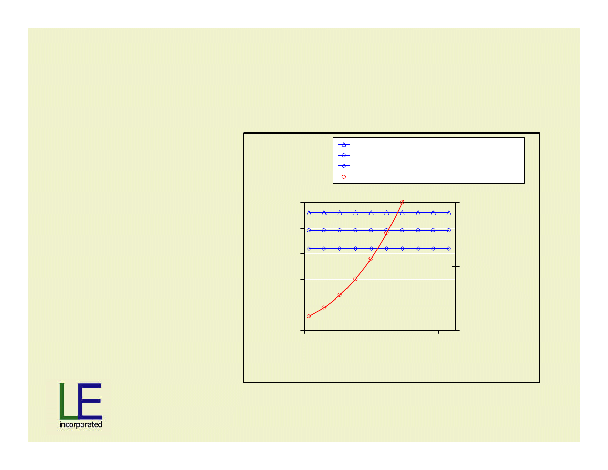
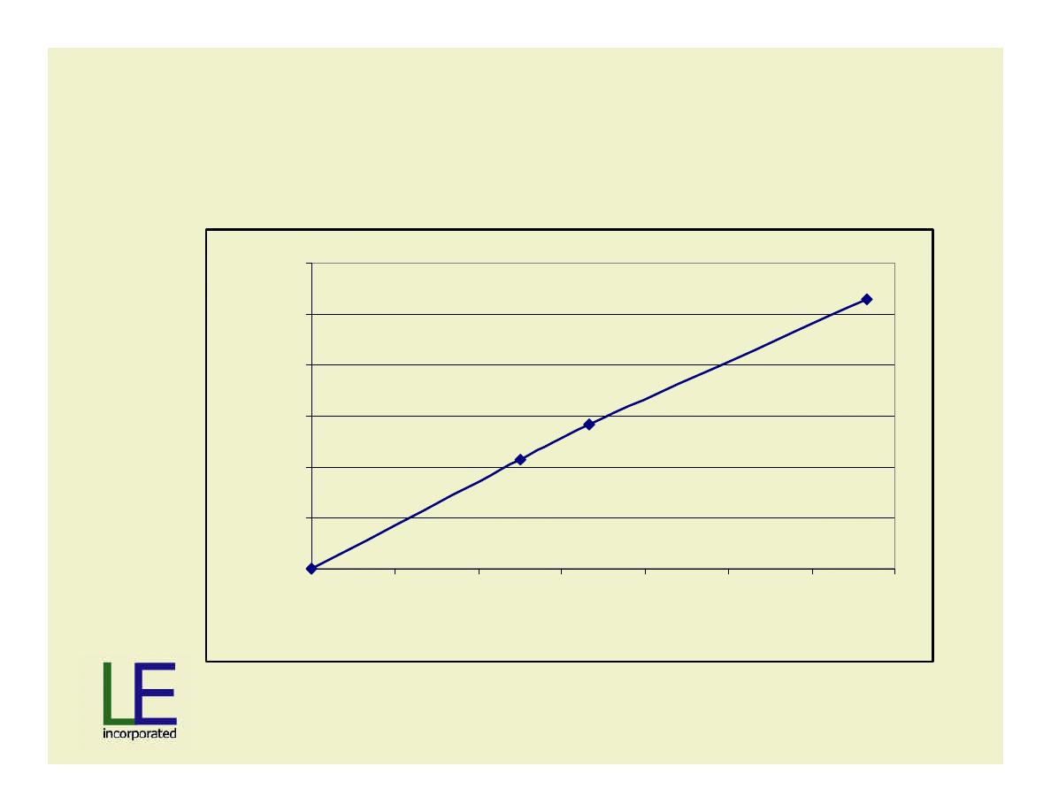
Wind Generator Goal
Power Output and Terminal Voltage
250
300
350
400
450
500
900
1400
1900
2400
Speed, RPM
Voltage
0
20
40
60
80
100
120
kW Power
Output Voltage, max
Output Voltage, nom
Output Voltage, min
Target Power ~ Rotor Speed Cubed
•Power ~ rotor-speed
3
•Voltage > 410 Vrms
•Voltage < 480 Vrms
Slide 5
Material
Patent Pending
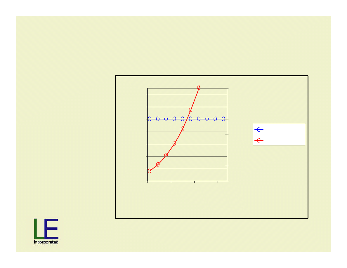
Wind Generator Goal
Power Output and Machine Efficiency
85%
87%
89%
91%
93%
95%
97%
99%
900
1400
1900
2400
Speed, RPM
Percent
0
20
40
60
80
100
120
kW Power
Target Efficiency
Target Power

Slide 6
Material
Patent Pending
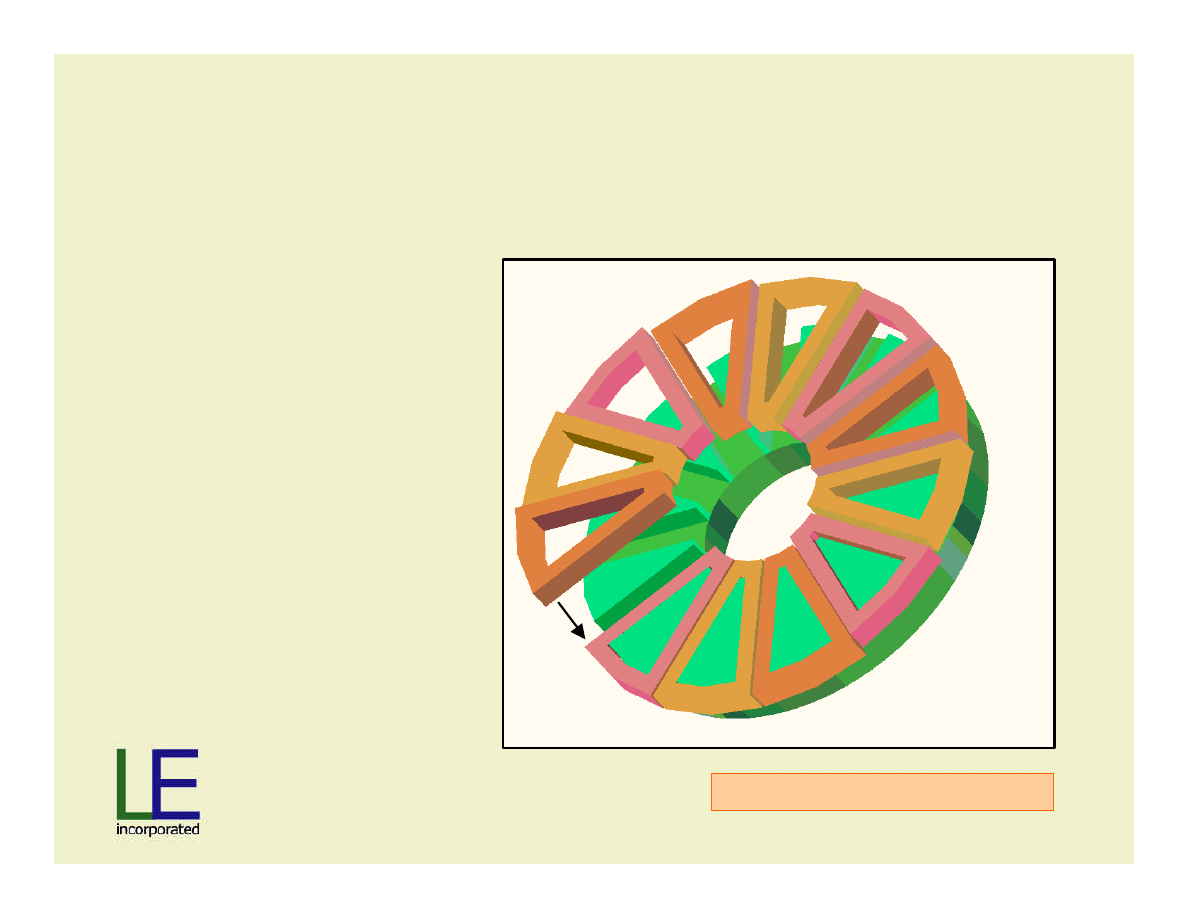
Axial Airgap Stator:
Example with 12 slots
Maxwell 3D Magnetostatic
•One stator shown
•Single wound
amorphous metal
ribbon, followed by
slot cutting
Slide 7
Material
Patent Pending
Stator shown with Phase Coils
Maxwell 3D Magnetostatic
•0.5 slots/phase/pole
•Discrete coils
•Wired A-B-C-A-B-C
C
A
B
B
C
A
Slide 8
Material
Patent Pending
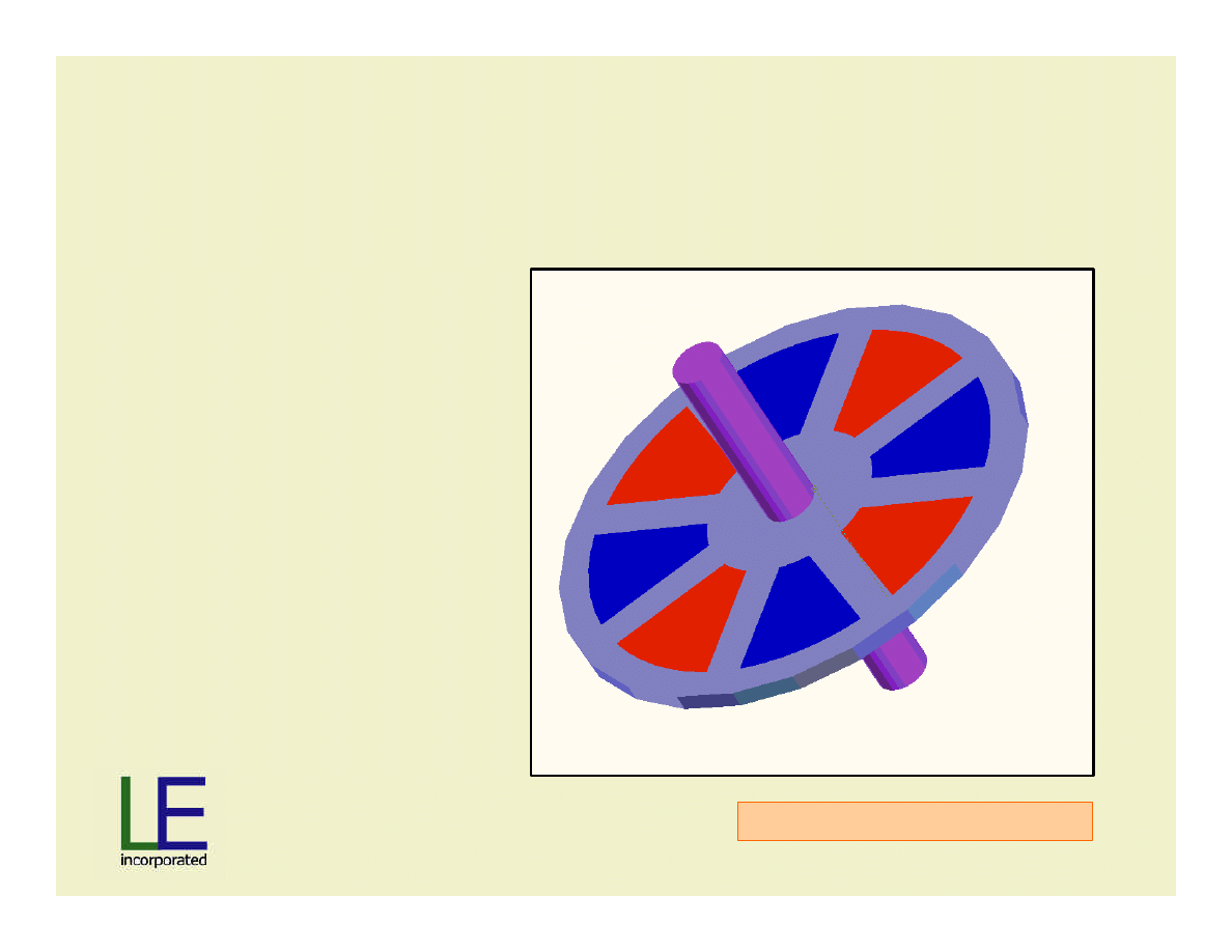
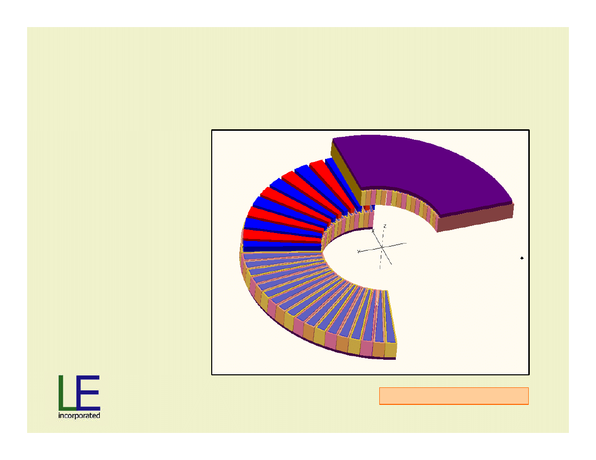
Axial-Gap Rotor and Shaft: 8 Poles
Maxwell 3D Magnetostatic
•Surface magnets
(thru rotor)
•North red
•South blue
•Shaft and rotor
shown for clarity
Slide 9
Material
Patent Pending
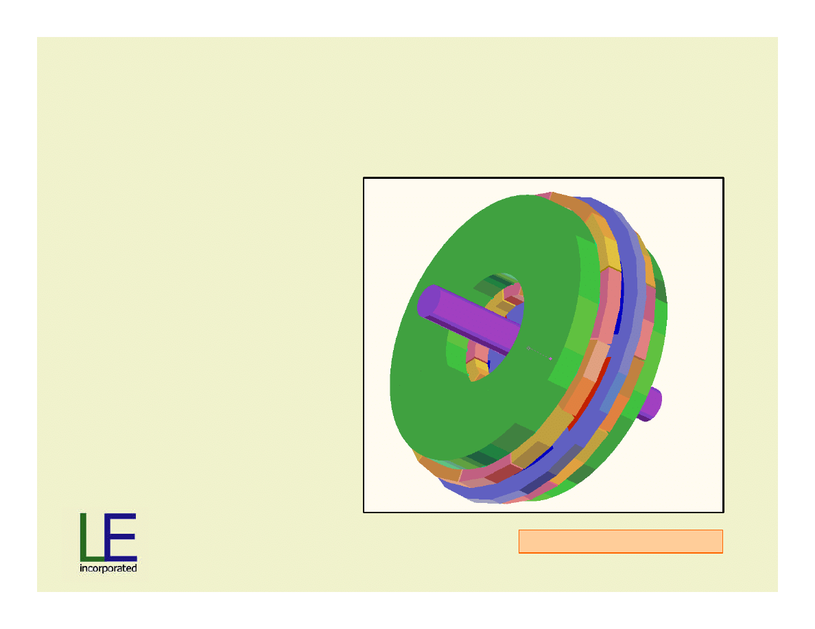
Complete Axial-Gap Machine: 12 Slots
Maxwell 3D Magnetostatic
•One rotor assembly
•Two stator assemblies
•Housing not shown

Slide 10
Material
Patent Pending
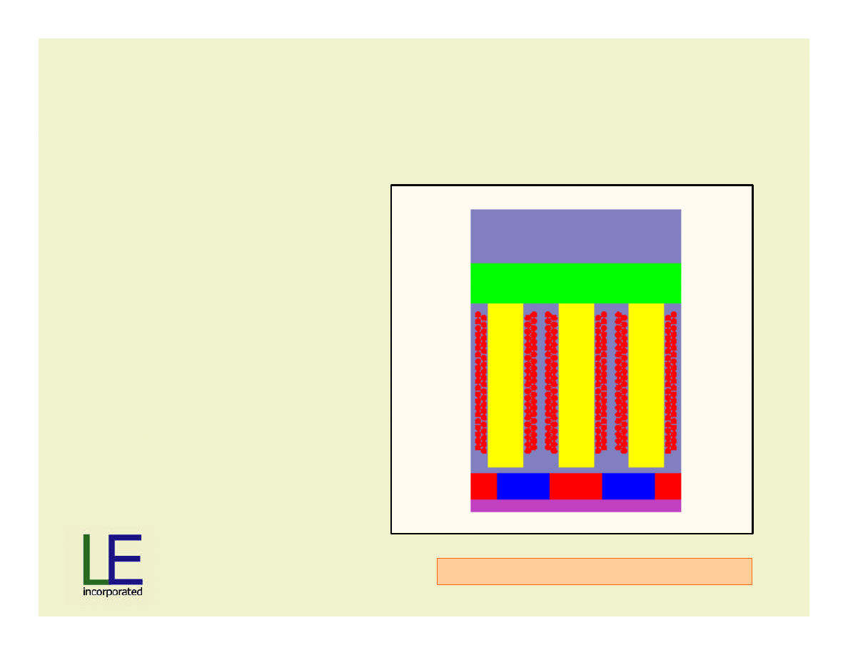
Minimum Machine for EM Analysis
•Shaft and disk not
needed for analysis
•Actual airgap 2.5 mm
Maxwell 3D Magnetostatic
A
C
B
Slide 11
Material
Patent Pending
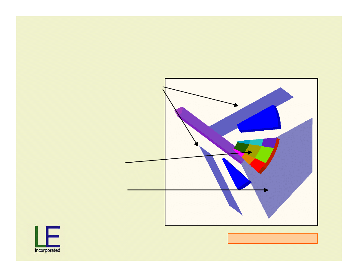
Boundary and Planar Entities: 12 Slots
Maxwell 3D Magnetostatic
•Master-slave boundaries
•Current sources (not
shown)
•Analysis surfaces;
orthogonal grid
•Tangent/normal
boundaries
Slide 12
Material
Patent Pending
Actual Sized Machine to meet
Project Specifications
•466 cm diameter
•13 cm axial length
•72 Slots
•24 Pole Pairs
Maxwell 3D Magnetostatic

Slide 13
Material
Patent Pending
Maxwell 3D Macro
•
1200 lines main code; 400 lines post processor code
•
Performs following:
•
Allows direct change to all parameters
•
Draws geometry
•
Assigns materials
•
Assigns boundaries
•
Defines solver options
•
Runs solver
•
Runs post processor macro
•
Writes inputs/outputs and writes to a .txt file
•
Iterates all of the above, on any variable
“Homegrown” Optimetrics
Slide 14
Material
Patent Pending
Variation in Flux Density Inside Coils
-1
-0.8
-0.6
-0.4
-0.2
0
0.2
0.4
0.6
0.8
1
1
2
3
4
5
6
7
8
Rotor Position
Tesla
A phase
B phase
C phase
Analysis for 1/6
of synchronous
cycle, i.e. 1/6 of
pole-pair angle.
Observation of
symmetry
concludes that
this is all the
analysis needed.
Slide 15
Material
Patent Pending
“Assembled” Variation in Flux Density
•Assembly of
synchronous
cycle from 1/6
analysis
•Makes macro
code much
faster and much
easier to write
-1
-0.8
-0.6
-0.4
-0.2
0
0.2
0.4
0.6
0.8
1
1
7
13
19
25
31
37
43
49
55
Rotor Position
Tesla
A phase
B phase
C phase

Slide 16
Material
Patent Pending
Results from Macro
•
Cogging
•
Ripple
•
Flux in core and backiron
•
Flux variation in magnet – demagnetization potential
•
Axial Forces
•
Limited by your code

Slide 17
Material
Patent Pending
On to the Solution
•
Need…
•
Constant Voltage plus
•
Increasing Speed plus
•
Increasing Power plus
•
Permanent magnet equals
•
….
•
Not possible (?)
Slide 18
Material
Patent Pending
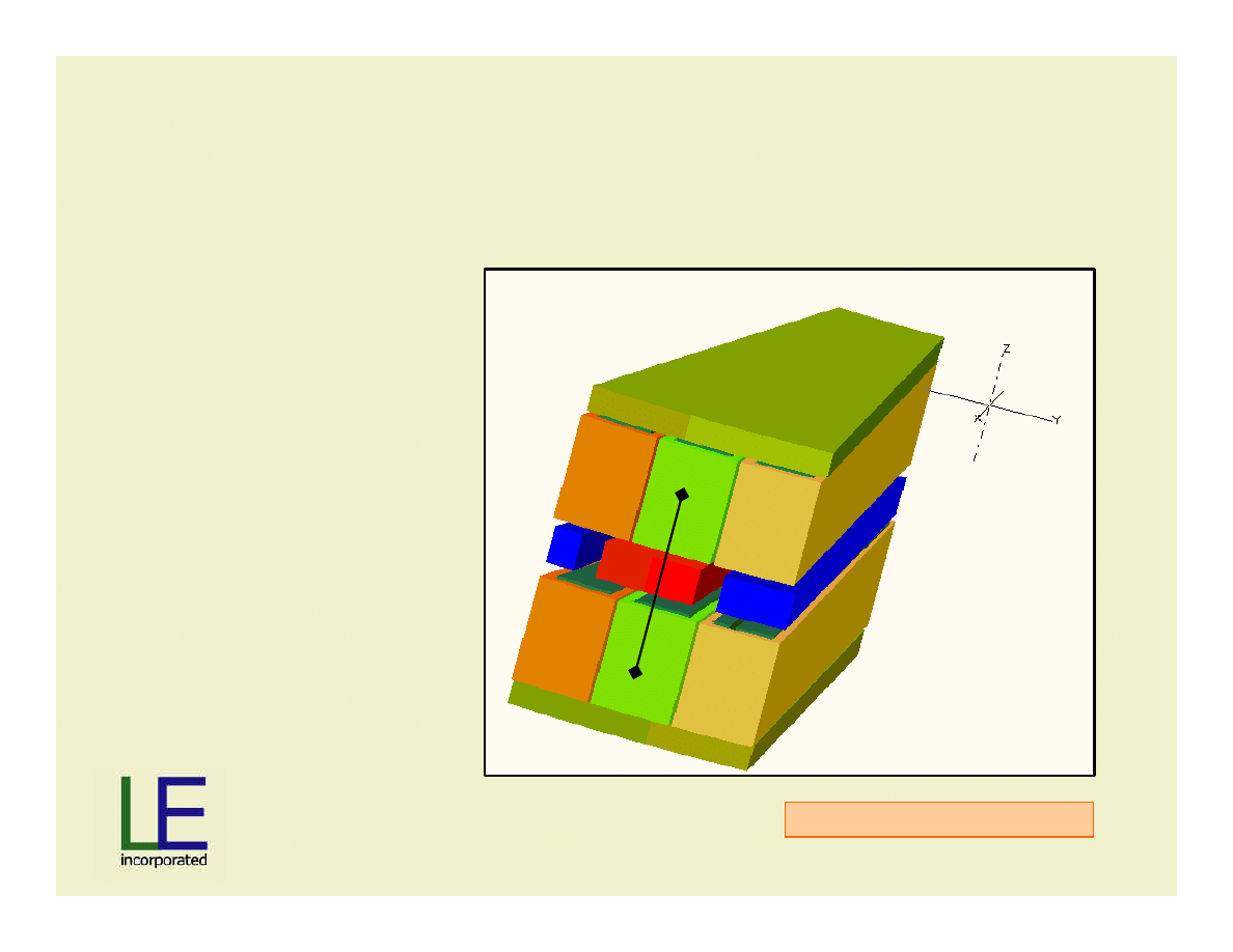
Stators In-line
Standard stator
arrangement: Both
stators are
physically in-line,
causing series
connected voltage
to add to 2X single-
side voltage.
Maxwell 3D Magnetostatic
Slide 19
Material
Patent Pending
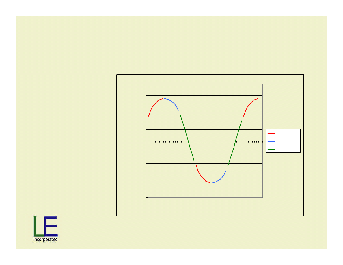
Stator Shifting: Method of EMF Control by
Relative Rotation about Z-axis
Upper stator section is kept
fixed relative to the rotation
about z-axis of the lower
section.
Previously in-phase coils
are taken out of phase.
Series connection causes
additive resulting sine-
wave voltage.
Maxwell 3D Magnetostatic
Slide 20
Material
Patent Pending
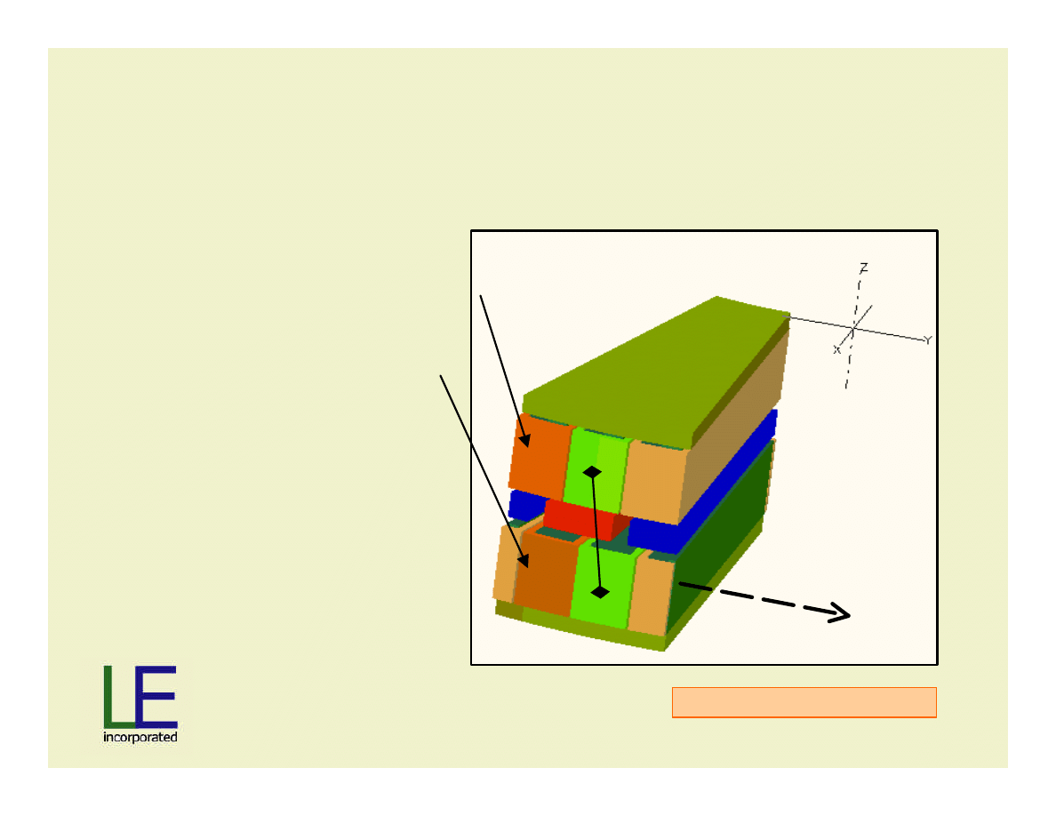
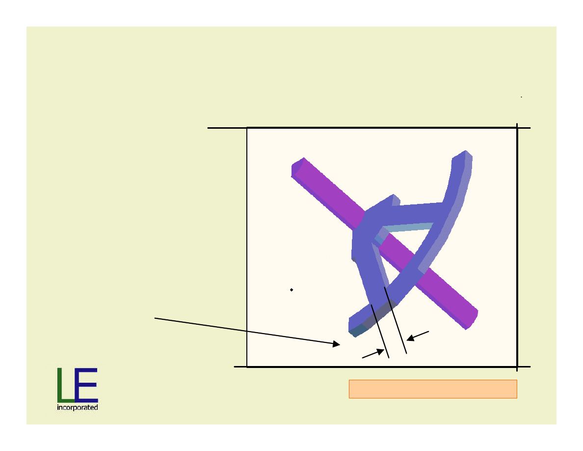
Stator Movement: Method of EMF Control by
Relative Rotation
Maxwell 3D Magnetostatic
Amount of relative
rotation …
never greater than …
1 pole pitch; in this
example 1 pole pitch
~30 mm.

Slide 21
Material
Patent Pending
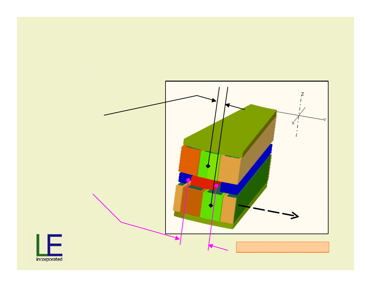
How much movement?
•
1 Pole Pitch = 7.5 degrees
•
1 Pole Pitch ~ 30mm circumferentially
•
1 Slot Pitch = 2/3 Pole Pitch
Slide 22
Material
Patent Pending
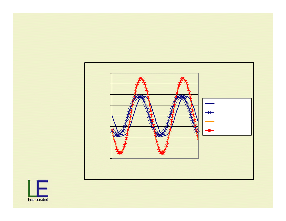
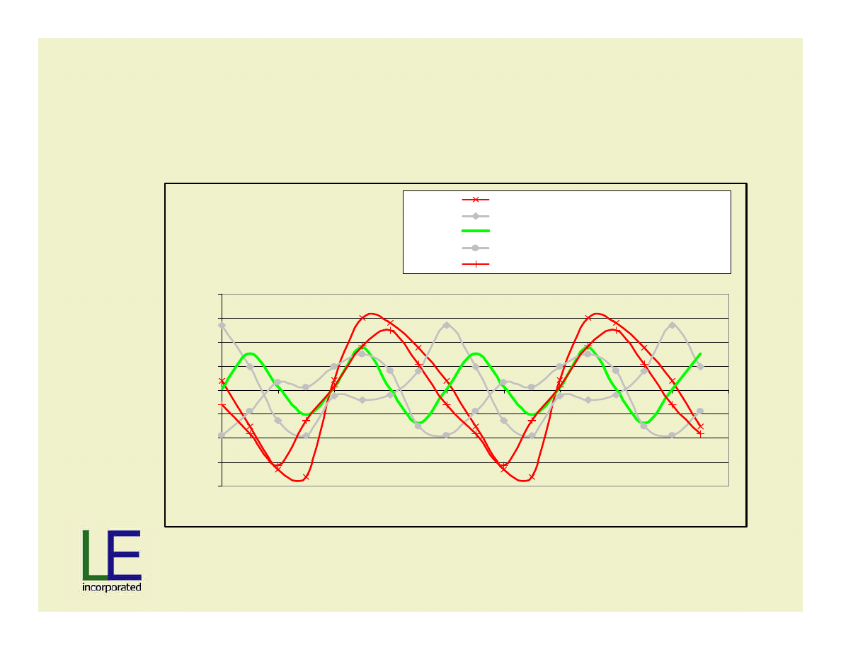
Stators Shifted by 25% Pole Pitch with Serial
Addition of Waveforms
•No load
-2
-1.5
-1
-0.5
0
0.5
1
1.5
2
Rotor Position
Tesla
Stator fixed
Stator shift 25%
Series stators
Best Fit Series
•THD=2%
Slide 23
Material
Patent Pending
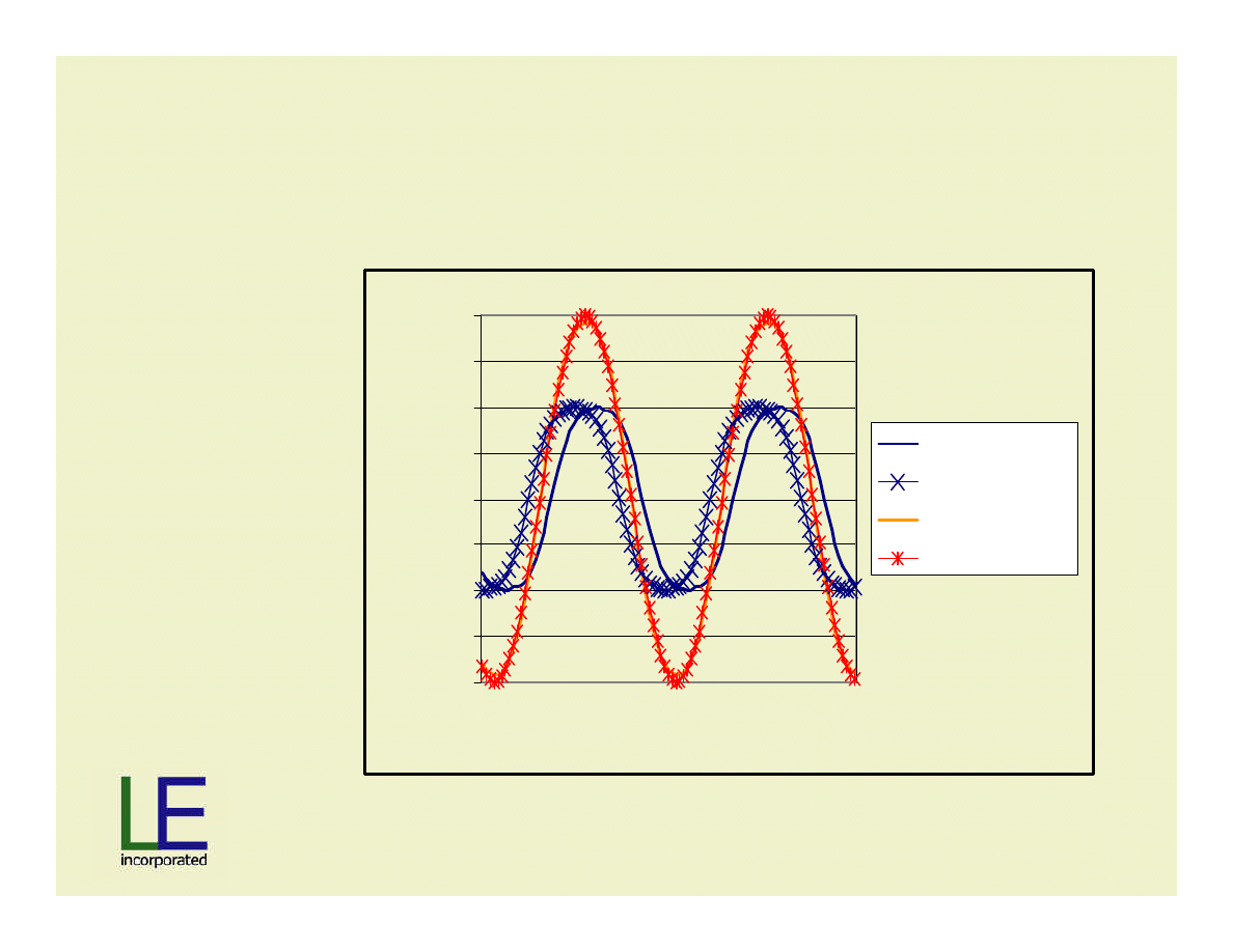
Stators Shifted by 25% Pole Pitch with Serial
Addition of Waveforms
-2
-1.5
-1
-0.5
0
0.5
1
1.5
2
Rotor Position
Tesla
Stator fixed
Stator shift 25%
Series stators
Best Fit Series
•Rated load
•THD=4%

Slide 24
Material
Patent Pending
Stators Shifted by 66% Pole Pitch with Serial
Addition of Waveforms
-2
-1.5
-1
-0.5
0
0.5
1
1.5
2
Rotor Position
Tesla
Stator fixed
Stator shift 66%
Series stators
Best Fit Series
•No load
•THD=7%
Slide 25
Material
Patent Pending
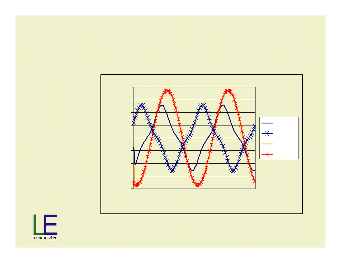
Stators Shifted by 66% Pole Pitch with Serial
Addition of Waveforms
-2
-1.5
-1
-0.5
0
0.5
1
1.5
2
Rotor Position
Tesla
Stator fixed
Stator shift 66%
Series stators
Best Fit Series
•Rated load
•THD=20%
Slide 26
Material
Patent Pending
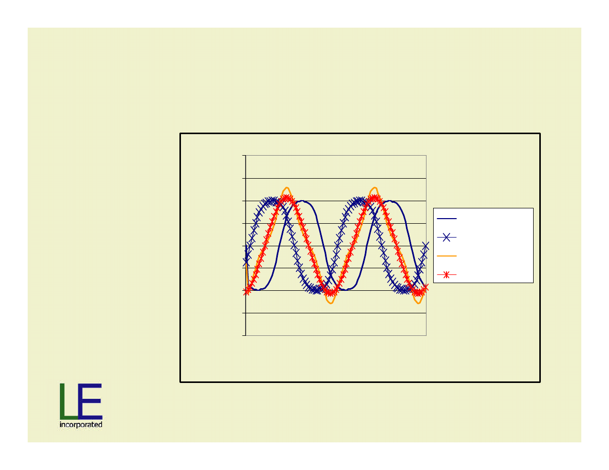
Stators Shifted by 66% Pole Pitch with Serial
Line-Line Waveform
•Rated load
•THD=6%
-2
-1.5
-1
-0.5
0
0.5
1
1.5
2
Rotor Position
Tesla
Phase A
Phase B
Line A-B
Best Fit

Slide 27
Material
Patent Pending
How is this all useful?
•
Find a machine solution, passive rectification using
basic phasor diagrams and algebra
•
Solve at lowest speed, 0% shift
•
Solve at increasing speed, while increasing the stator
shift to keep terminal voltage near constant
•
Solution: 73% pole pitch shift needed = 22 mm
movement circumferentially

Slide 28
Material
Patent Pending
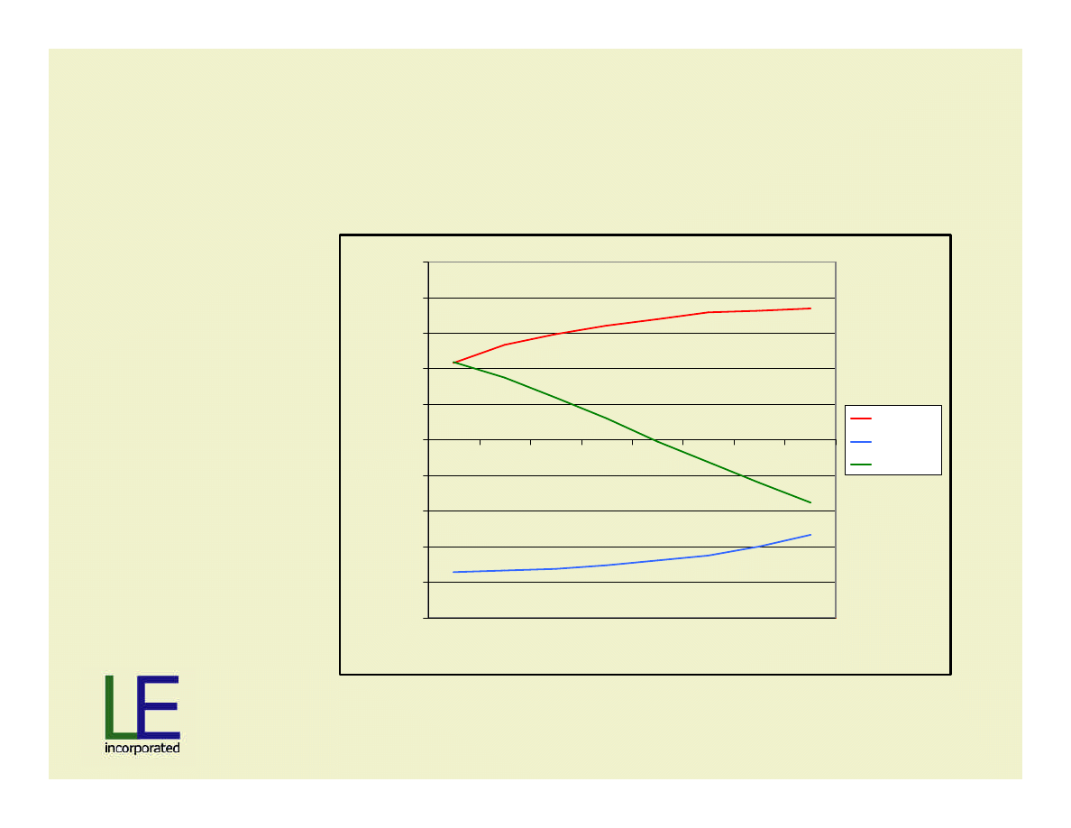
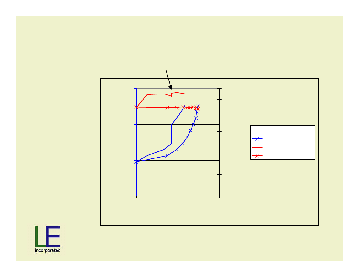
Results Voltage vs. Target Voltage
300
350
400
450
500
550
600
900
1400
1900
2400
Speed, RPM
Voltage
V @ max power
V @ min power
target V nominal
Slide 29
Material
Patent Pending
300
350
400
450
500
550
600
900
1400
1900
2400
Speed, RPM
Voltage
0
20
40
60
80
100
120
kW Power
target V nominal
Target Power
max power
min power
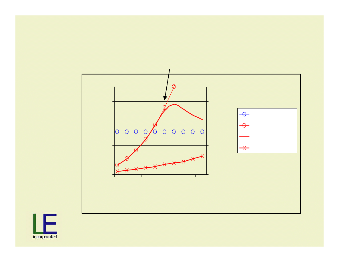
Results Power vs. Target Power
Voltage would be exceeded
So power cannot be maintained
Slide 30
Material
Patent Pending
85%
87%
89%
91%
93%
95%
97%
99%
900
1400
1900
2400
Speed, RPM
Percent
Eff @ max power
Eff @ min power
Target Efficiency
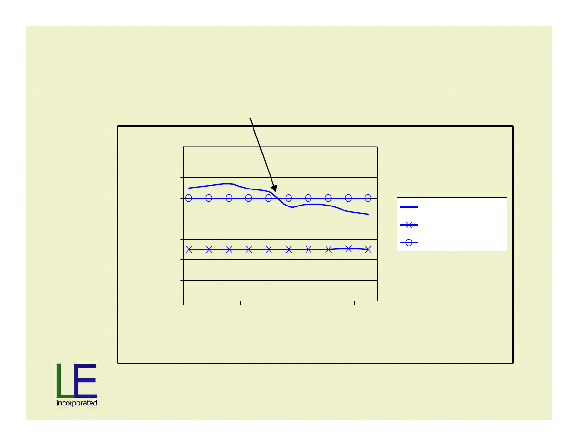
Results Efficiency vs. Target Efficiency
Voltage would be exceeded
So current must increase
Slide 31
Material
Patent Pending
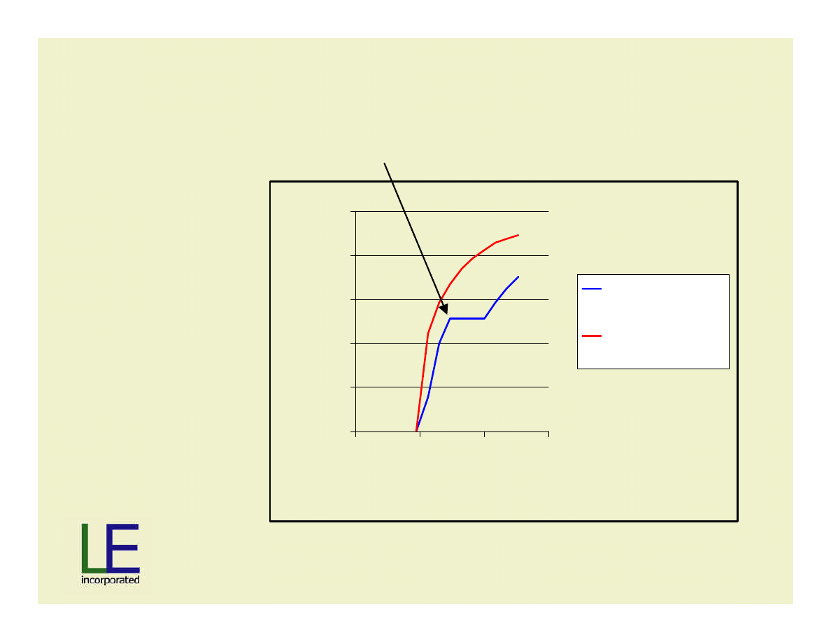
Resulting needed Stator Movement
0.0
5.0
10.0
15.0
20.0
25.0
0
1000
2000
3000
Speed, RPM
mm
circum movement
for max power
circum movement
for min power
Ref:
30 mm=pole pitch
20 mm=slot pitch
Voltage would be exceeded
Slide 32
Material
Patent Pending
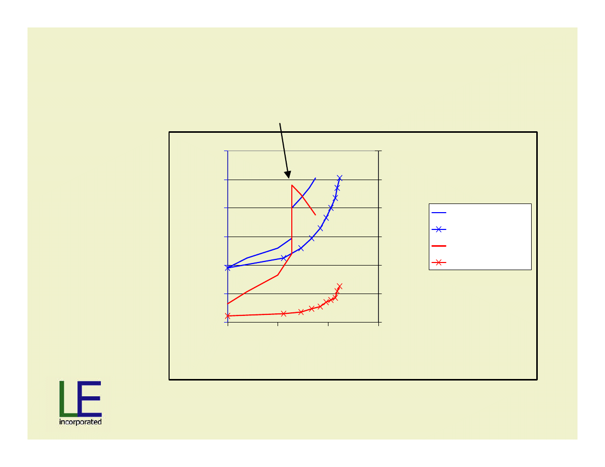
Speed and Power vs. Stator Position
0
500
1000
1500
2000
2500
3000
0.0
10.0
20.0
30.0
movement, mm
speed, RPM
0
20
40
60
80
100
120
Power, kW
spd @ max power
spd @ min power
max power
min power
Voltage would be exceeded
Slide 33
Material
Patent Pending
Speed and Voltage vs. Stator Position
0
500
1000
1500
2000
2500
3000
0.0
10.0
20.0
30.0
movement, mm
speed, RPM
0
50
100
150
200
250
300
350
400
450
500
Voltage
spd @ max power
spd @ min power
V @ max power
V @ min power
Voltage would be exceeded
Slide 34
Material
Patent Pending
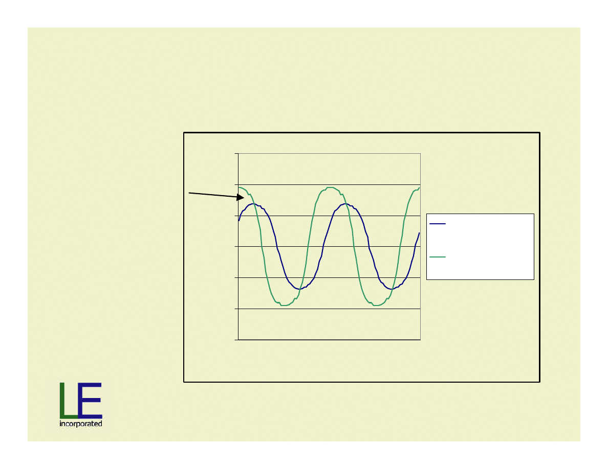
Other items of interest:
Flux Density in Backiron
Discontinuity is
not real, it’s a
function of
solver accuracy
-1.5
-1
-0.5
0
0.5
1
1.5
Rotor Position
Tesla
no load B in
backiron
load B in backiron
Slide 35
Material
Patent Pending
Cogging Controlled via 3D Optimized
Magnet Spacing
Maxwell 3D Magnetostatic
Typical approach to
design minimal
cogging into
machine is via 3D
analysis and
variation of magnet
spacing.
Slide 36
Material
Patent Pending
Stator Shifting and Effect on Cogging
-8
-6
-4
-2
0
2
4
6
8
0
2
4
6
8
10
12
14
16
18
Rotor Position
N-m
Pole Pitch 0% - Slot Pitch 0%
Pole Pitch 25% - Slot Pitch 38%
Pole Pitch 33% - Slot Pitch 50%
Pole Pitch 40% - Slot Pitch 60%
Pole Pitch 67% - Slot Pitch 100%
Slide 37
Material
Patent Pending
Unfortunately, Axial Forces Increase with
amount of Stator Shift
0
1000
2000
3000
4000
5000
6000
0%
10%
20%
30%
40%
50%
60%
70%
Pole Pitch Percent
Axial Force, N
Slide 38
Material
Patent Pending
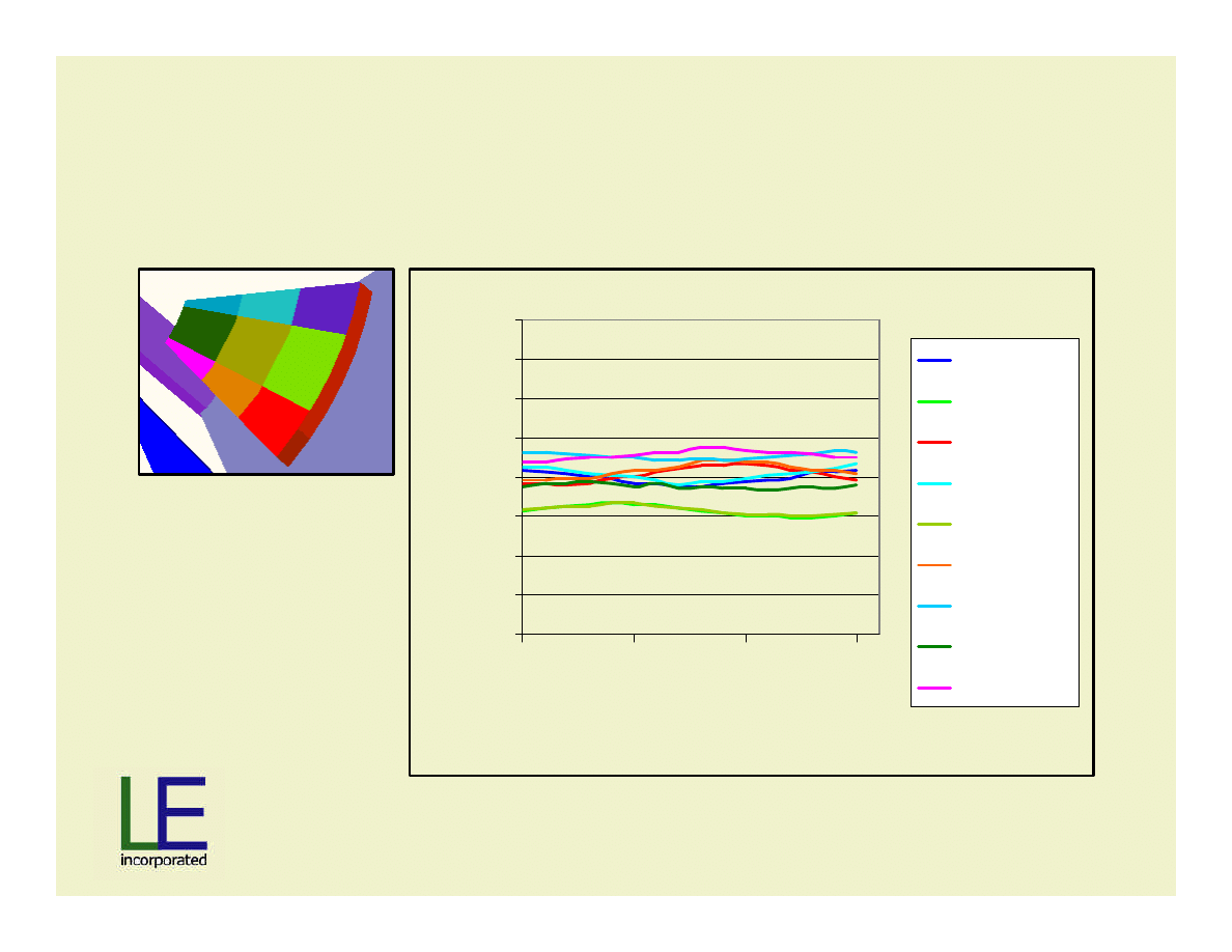
No Load;
Review Flux Density in Magnet Grid
0.4
0.5
0.6
0.7
0.8
0.9
1
1.1
1.2
0
5
10
15
Rotor Position
Tesla
Leading OR
Central OR
Trailing OR
Leading R
Central R
Trailing R
Leading IR
Central IR
Trailing IR
Slide 39
Material
Patent Pending
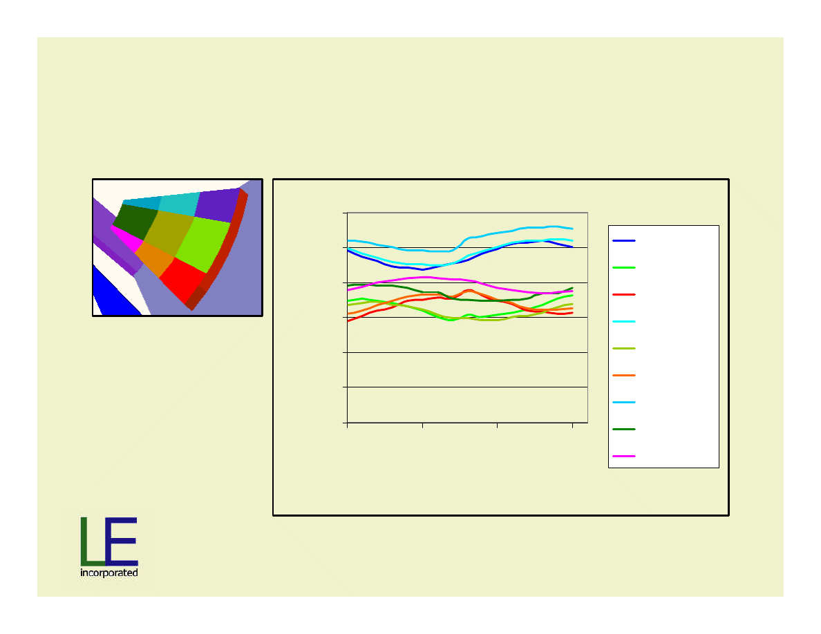
Rated Load;
Review Flux Density in Magnet Grid
0.4
0.5
0.6
0.7
0.8
0.9
1
0
5
10
15
Rotor Position
Tesla
Leading OR
Central OR
Trailing OR
Leading R
Central R
Trailing R
Leading IR
Central IR
Trailing IR
Slide 40
Material
Patent Pending
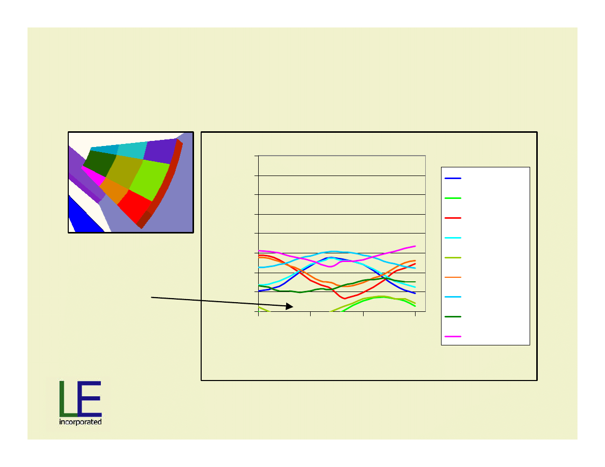
3X Rated Load; All current in D-axis
Review Flux Density in Magnet Grid
0.4
0.5
0.6
0.7
0.8
0.9
1
1.1
1.2
0
5
10
15
Rotor Position
Tesla
Leading OR
Central OR
Trailing OR
Leading R
Central R
Trailing R
Leading IR
Central IR
Trailing IR
De-magnetization
is a real concern!
Slide 41
Material
Patent Pending
A Plug for Maxwell 2D: AC Ohmic Loss
Maxwell 2D Transient Solver
•2D transient analysis
•Determines AC losses
•Due to proximity effects
•+/-20% error vs. test

Slide 42
Material
Patent Pending
Solution Results
á
Power = 98kW at 2000 rpm
á
Power follows rotor-speed
3
for 2X speed range
á
Voltage stays within 410 – 480 Vrms range
á
Efficiency > 94%
â
Harmonic content increases (changes) with Stator
Shift
â
Axial force increases with Stator Shift
Wyszukiwarka
Podobne podstrony:
Development Of Wind Power Control System For Six Phase Permanent Magnet Synchronous Generators
Control Issues Of A Permanent Magnet Generator Variable Speed Wind Turbine
A Low Speed, High Torque, Direct Drive Permanent Magnet Generator For Wind Turbines
Directly Driven Low speed Permanent Magnet Generators For Wind Power Application
(Wind) A Low Speed, High Torque, Direct Drive Permanent Magnet Generator For Wind Turbines
Design Of Direct Driven Permanent Magnet Generators For Wind Turbines
Abb 3,5Mw Permanent Magnet Generator
My Homemade wind generator
Plans For Wind Generator Pt250 Blade Plan10A
Modified PWM Control for the DC AC Inverter With a Non Constant Voltage Source
Wind Generator Project Wood X
An Igbt Inverter For Interfacing Small Scale Wind Generators To Single Phase Distributed Power Gener
Wind Generator Home Made Axial Flux Alternator Hugh Piggott Dec 18 06 Axial Flux Howitworks
Patent Of The Permanent Magnet Machine
permanent magnet motor controllers 1228
Eurocode 1 Part 1 5 2003 UK NA Actions on Structures General actions Thermal actions
więcej podobnych podstron