
10
. CRANKCASE/CRANKSHAFT
10-0
ZX / SCOUT 50
10
__________________________________________________________________________________
__________________________________________________________________________________
__________________________________________________________________________________
__________________________________________________________________________________
__________________________________________________________________________________
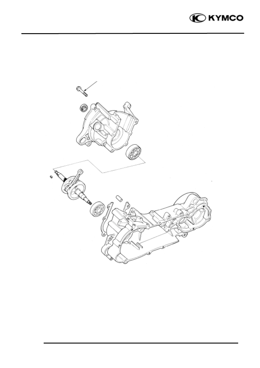
CRANKCASE/CRANKSHAFT
__________________________________________________________________________________
SERVICE INFORMATION........................................................ 10-2
TROUBLESHOOTING.............................................................. 10-2
CRANKCASE SEPARATION .................................................... 10-3
CRANKSHAFT REMOVAL....................................................... 10-3
CRANKSHAFT INSPECTION ................................................... 10-4
CRANKSHAFT INSTALLATION.............................................. 10-5
CRANKCASE ASSEMBLY ....................................................... 10-7
10
10
. CRANKCASE/CRANKSHAFT
10-1
ZX / SCOUT 50
Torque: 0.8_
1.2kg-m
10
. CRANKCASE/CRANKSHAFT
10-2
ZX / SCOUT 50
SERVICE INFORMATION
GENERAL INSTRUCTIONS
• This section covers crankcase separation to service the crankshaft.
• The following parts must be removed before separating the crankcase.
Engine (!Section 5)
Driven pulley (!Section 8)
Carburetor (!Section 11)
A.C. generator (!Section 7)
Oil pump (!Section 4)
Cylinder head/cylinder (!Section 6)
Reed valve (!Section 11)
• When the left crankcase must be replaced, remove the following part in addition to the above.
Final reduction removal
• Special tools must be used for crankshaft and crankcase assembly. When separating the
crankcase, the bearing will remain in the crankcase and it should be removed. When, assembling,
drive a new bearing into the crankcase and install a new oil seal.
SPECIFICATIONS
SC10AS
Item
Standard (mm) Service Limit (mm)
Connecting rod big end side
clearance
æ
0.60
Connecting rod big end radial
clearance
æ
0.04
Crankshaft runout A/B
æ
0.15/0.10
SPECIAL TOOLS
Crankcase puller
Bearing outer driver handle A
Universal bearing puller
Bearing outer driver, 42x47mm
Crankcase assembly collar
Bearing driver pilot, 20mm
Crankcase assembly tool
Bearing outer driver, 37x40mm
Bearing driver pilot, 17mm
TROUBLESHOOTING
Abnormal engine noise
• Excessive crank journal bearing play
• Excessive crankpin bearing play
• Excessive transmission bearing play
10
. CRANKCASE/CRANKSHAFT
10-3
ZX / SCOUT 50
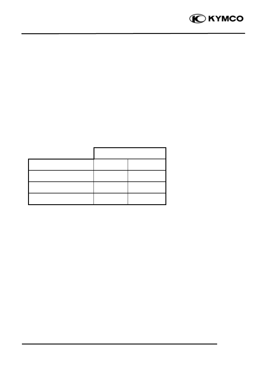
CRANKCASE SEPARATION
Remove the crankcase attaching bolts.
Attach the crankcase puller on the right
crankcase and remove the right crankcase
from the left crankcase.
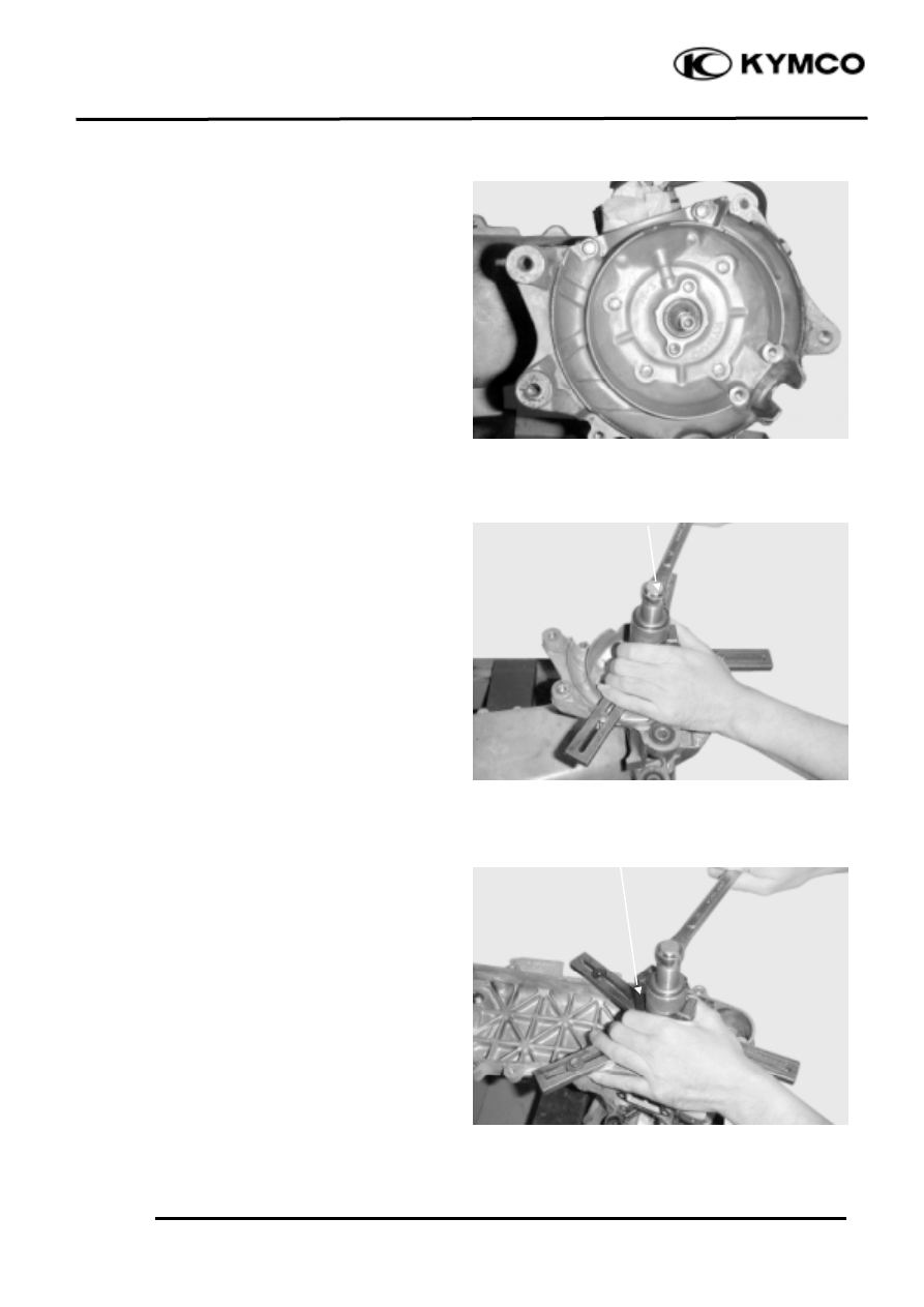
CRANKSHAFT REMOVAL
Attach the crankcase puller on the left
crankcase and remove the crankshaft from
the left crankcase.
Crankcase Puller
Crankcase Puller
10
. CRANKCASE/CRANKSHAFT
10-4
ZX / SCOUT 50
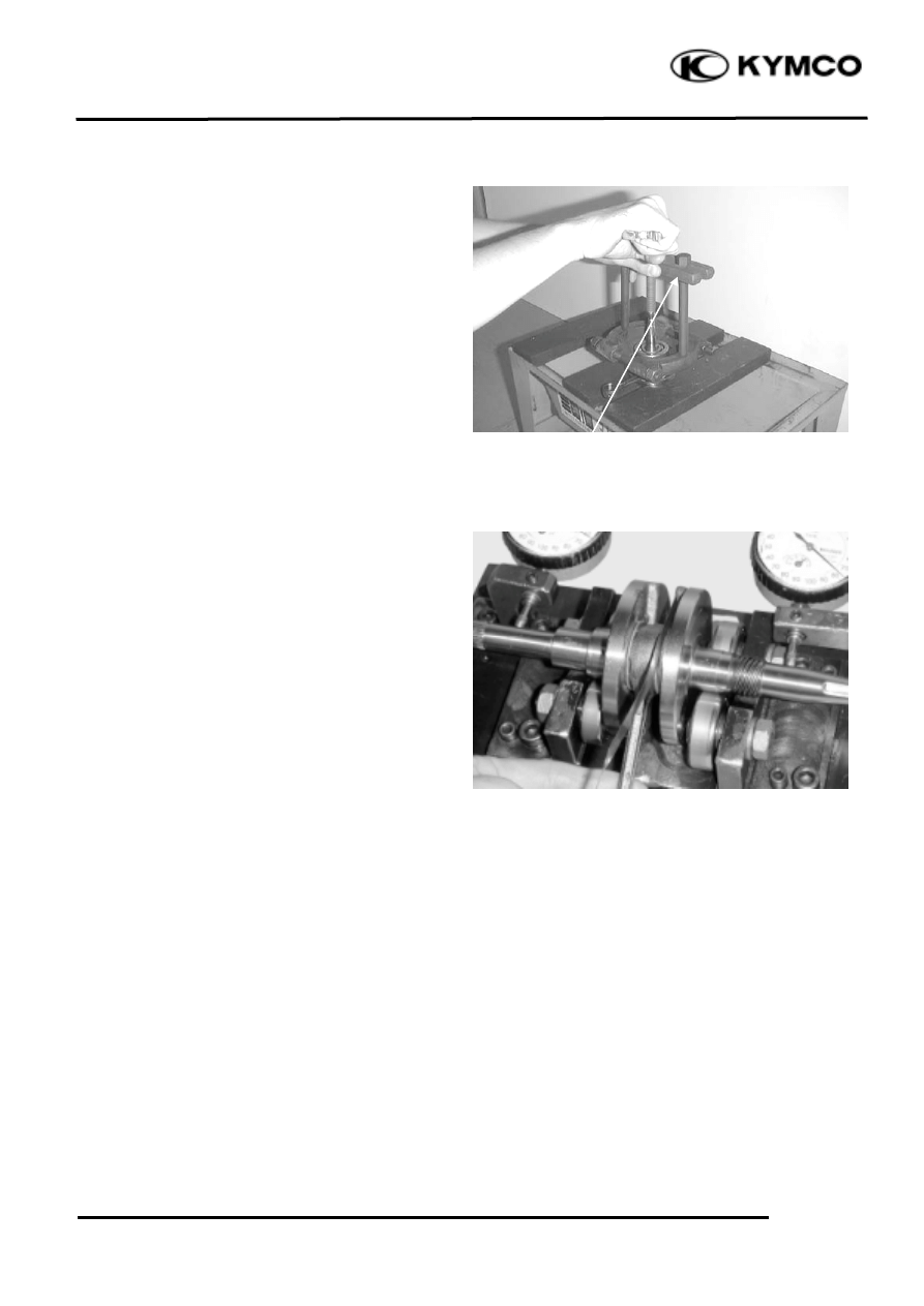
Remove the remaining bearing on the
crankshaft side using the universal bearing
puller.
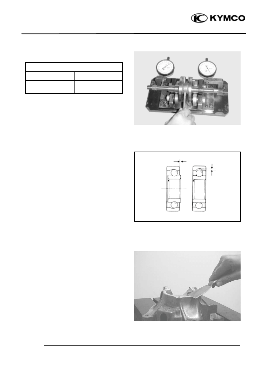
CRANKSHAFT INSPECTION
Measure the connecting rod big end side
clearance.
Service Limit: 0.6mm replace if over
Measure the connecting rod big end radial
clearance at two points in the X and Y
directions.
Service Limit: 0.04mm replace if over
Universal Bearing Puller
10
. CRANKCASE/CRANKSHAFT
10-5
ZX / SCOUT 50
Measure the crankshaft runout.
Service Limit
A
B
0.150mm
replace if over
0.100mm
replace if over
Check the crankshaft bearings for excessive
play. The bearings must be replaced if they
are noisy or have excessive play.
CRANKSHAFT INSTALLATION
Wash the crankshaft in cleaning solvent and
then check for cracks or other faults.
Axial
Play
Play
Radial
10
. CRANKCASE/CRANKSHAFT
10-6
ZX / SCOUT 50
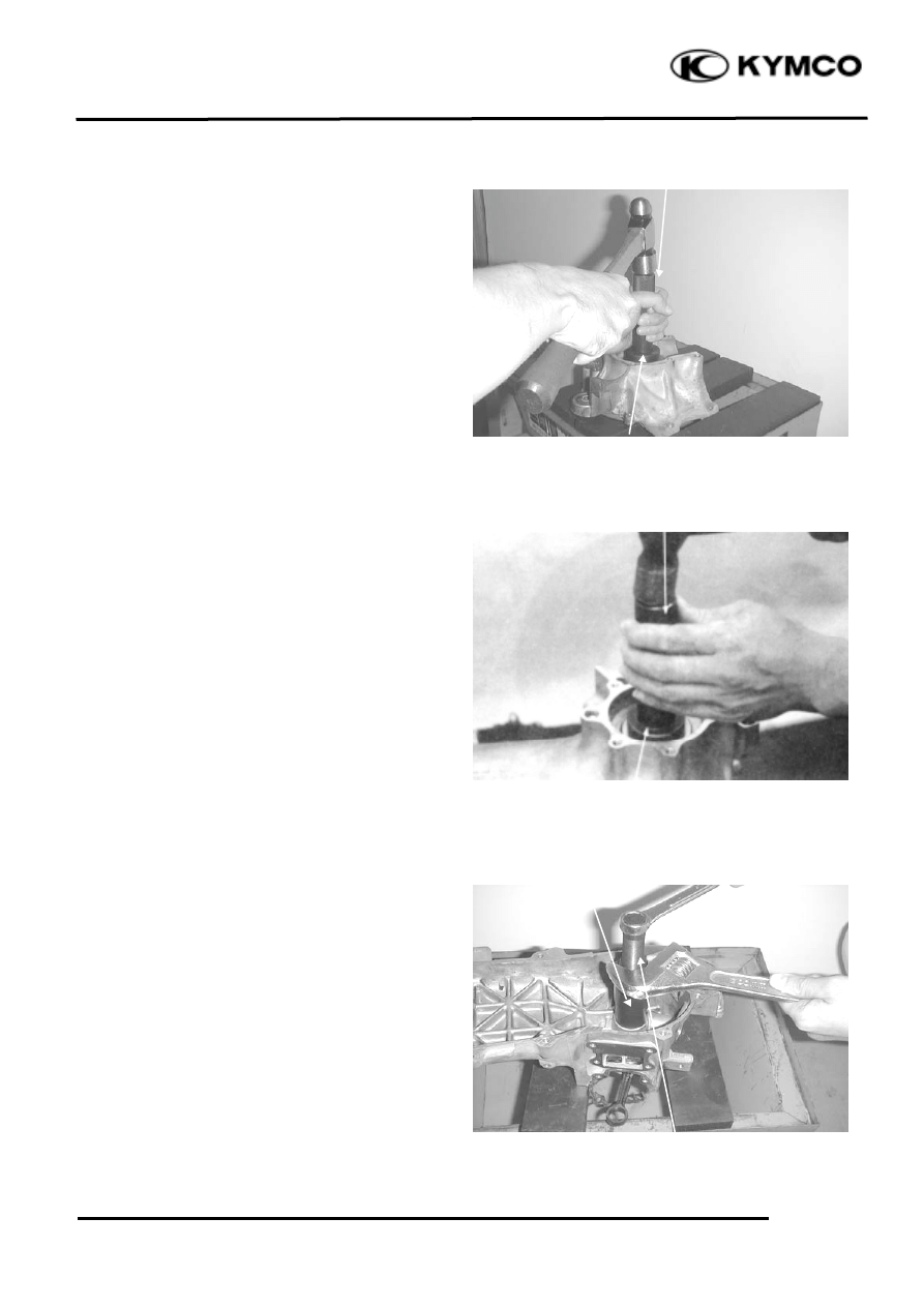
Drive a new crankshaft bearing into the
right crankcase.
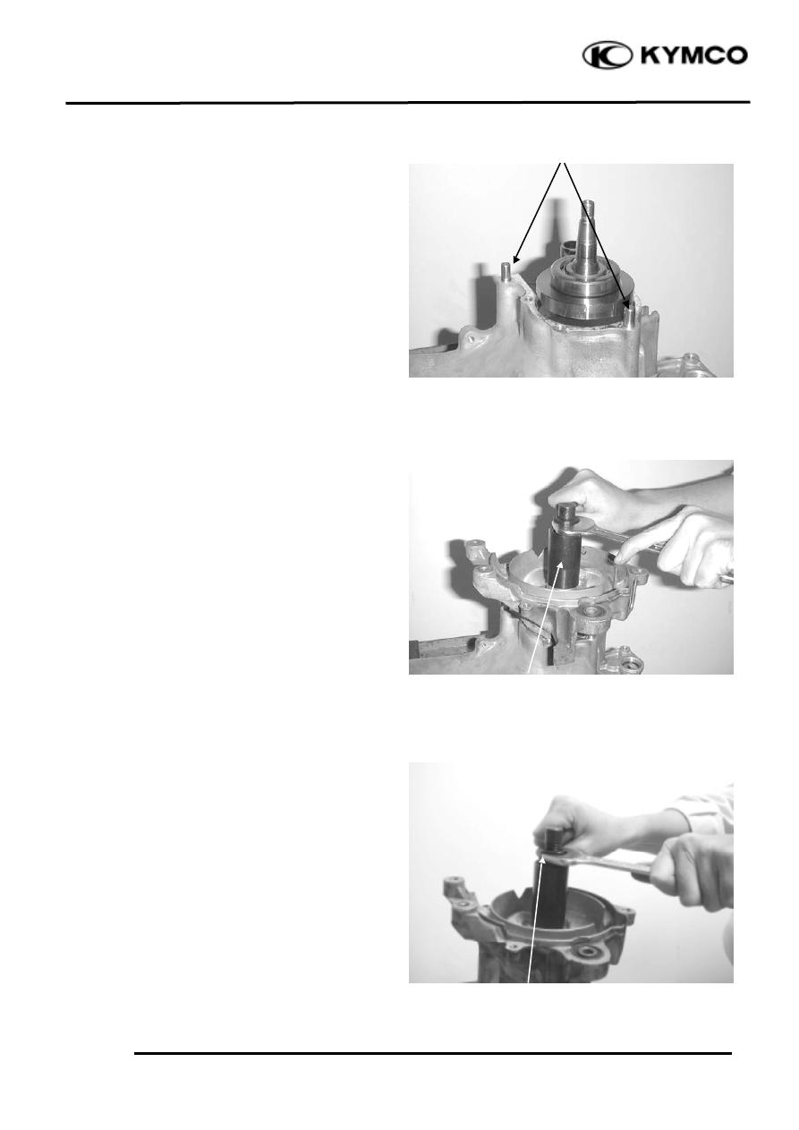
Drive a new crankshaft bearing into the left
crankcase.
Install the crankshaft into the left crankcase.
Bearing Outer Driver Handle A
Bearing Outer Driver Handle A
Bearing Outer Driver, 37x40mm
Bearing Driver Pilot, 17mm
Bearing Outer Driver, 42x47mm
Pilot, 20mm
Crankcase Assembly Tool
Crankcase Assembly Collar
10
. CRANKCASE/CRANKSHAFT
10-7
ZX / SCOUT 50
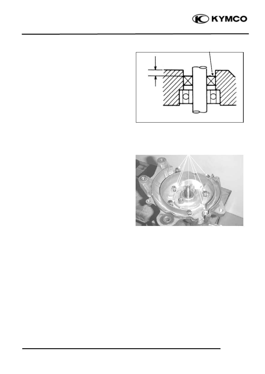
CRANKCASE ASSEMBLY
Install the dowel pins and a new gasket to
the crankcase mating surface.
Assemble the crankcase halves.
The distance between the right crankcase oil
seal and crankcase surface is about 12.5±0.5
mm.
Dowel Pins
Crankcase Assembly Tool
Crankcase Assembly Tool
10
. CRANKCASE/CRANKSHAFT
10-8
ZX / SCOUT 50
The distance between the left crankcase oil
seal and crankcase surface is about 1.0mm.
Install and tighten the crankcase attaching
bolts.
Oil Seal
1.0mm
Bolts
Wyszukiwarka
Podobne podstrony:
ZX50 cap 05 (rimozione motore)
ZX50 cap 12 (plastiche)
ZX50 cap 09 (riduzione finale)
ZX50 cap 08 (trasmissione)
ZX50 cap 00 (prefazione)
ZX50 cap 04 (lubrificazione)
ZX50 cap 11 (carburatore)
ZX50 cap 07 (statore volano)
ZX50 cap 14 (ruota freno sospensione post)
focal infection cap 10
ZX50 cap 01 (indice e specifiche)
ZX50 cap 16 (strumentazione interruttori luci)
ZX50 cap 13 (manubrio ruota freno sospens ant)
ZX50 cap 02 (info generali)
ZX50 cap 17 (imp scarico)
więcej podobnych podstron