MANUALE INSTALLAZIONE E REGOLAZIONE
pag.
3
INSTALLATION AND ADJUSTMENT MANUAL
page
7
MANUEL INSTALLATION ET REGLAGE
page
11
GUIA INSTALLACION Y REGULACION
pag.
16
RIDUTTORI ‘SE 81 SIC’ GPL
‘SE 81 SIC’ LPG REGULATORS
REDUCTEUR ‘SE 81 SIC’ GPL
REDUCTORES ‘SE 81 SIC’ GLP
LPG & CNG CONVERSION SYSTEMS FOR VEHICLES
1
9
0
1
5
7
4
4
0
/1
LANDI RENZO S. p. A. - Via F.lli Cervi, 75/2 - 42100 Reggio Emilia - Italy
Tel. +39 / 0522.382678 - Fax +39 / 0522.382906
E-mail: info@landi.it - Internet Site: http://www.landi.it
LANDI RENZO S.p.A.
RID. GPL ‘SE81 SIC’ / ‘SE81 SIC’ LPG REG. / DET. ‘SE81 SIC’ GPL / RED. ‘SE81 SIC’ GLP
2 / 19
Schemi Tecnici
Technical Drawings
Schémas Techniques
Esquemas Técnicos
Fig. 1
Fig. 2

LANDI RENZO S.p.A.
‘SE 81 SIC’ LPG REGULATORS INSTALLATION AND ADJUSTMENT MANUAL
7 / 19
Legend
Specification
Thank you for purchasing a LANDI RENZO
pressure regulator type ‘SE 81 SIC’, the reliable
and technologically advanced device to install a
LPG conversion system on vehicles with catalytic
converter, injection system, carburettor and turbo-
charger.
Correctly installed, your pressure regulator will
give many years of excellent performance.
To ensure that you achieve peak performance
from the conversion system, please read this
installation and setting guide thoroughly.
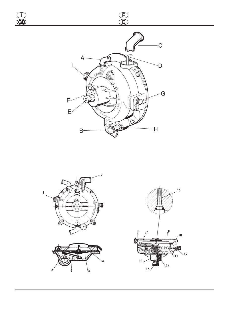
LEGEND (Fig. 1)
A) Water outlet union for connection to a water
coolant system return duct
B) Water inlet union for connection to a water
coolant system delivery duct
C) Gas outlet connector
D) Idle speed pipe (to position always at the
same direction of gas outlet connector)
E) Idle speed setting screw
F) Plus/minus contact for idle speed solenoid
valve
G) Sensitivity screw
H) Regulator bleeder plug
I) Gas inlet union
1. TECHNICAL SPECIFICATION
Electronic control device to reduce the LPG
pressure and vaporize it allowing a regular flow of
gas whenever the engine requires it.
It is equipped with two LPG reduction stages that
allow stability at both high and low pressures.
The passage of LPG from the liquid to the gas
phase takes place by a drop in pressure and by
absorption of the heat taken from parts of the
regulator, heated with the liquid of the engine
cooling circuit.
The flow of gas necessary for engine idling has a
positive pressure from the first stage and is
activated by means of a gas pipe separated from
the main flow. It includes an electronic starting
device with a built-in safety system that trips and
shuts off the gas solenoid valves if the engine is
switched off or even stalled.
Operation
SPECIFICATION:
Regulator type: 2 stages with electronic starting
device and idling at positive pressure
Use: automotive (suitable for vehicles with
catalytic converter, injection, carburettor and
turbo-charger)
Type of fluid: LPG (liquefied petroleum gas)
Body: GDALSI 13 Fe UNI 5079
Heating: engine cooling circuit liquid
Test pressure: 45 bar
First stage adjustment pressure: 0.8 bar
Power supply: 12V DC
Coil power capacity: 18W
VERSIONS:
SE 81 SIC (standard): up to 130 HP
SE 81 SIC (oversize): from 130 HP to 250 HP
SE 81 SIC (super oversize): over 250 HP
SE 81 SIC Turbo: for turbo-charged engines up to
200 HP
2. REGULATOR OPERATION (Fig. 2)
L.P.G. passes the gas inlet union (1) and valve (2)
before entering the first-stage chamber (3). Gas
flow is metered by the gas on diaphragm. (4). This
pressure causes a dilation which overcomes the
resistance of spring (5) and operates lever (6)
which controls the opening and closing of the first-
stage valve (2).
Via gas outlet (7) the engine intake system
generates vacuum in the second stage chamber
and causes diaphragm (8) to move axially.
Being connected to level (9), the diaphragm
controls valve (10) opening thus allowing the gas
to reach the second-stage chamber via duct (11)
and then the engine via gas outlet (7). Valve (10)
and lever (9) are sealed when spring (12) is
adequately set.
The starting and idle-speed device consists of
solenoid valve (13) which is controlled via an
electronic device. Plunger (14) moves thus leaving
hole (15) open. The gas coming from the first-
stage chamber (3) flows out of this hole thus
allowing the engine to run at idle speed. If the
engine stops, the coil becomes de-energized and
plunger (14) closes outlet hole (15). Idle-speed
setting is achieved via adjuster (16).
At starting, the electronic device energizes coil
(13) so that plunger (14) leaves hole (15) open
thus letting the required amount of gas through.

LANDI RENZO S.p.A.
‘SE 81 SIC’ LPG REGULATORS INSTALLATION AND ADJUSTMENT MANUAL
8 / 19
Notices
3. GENERAL NOTICES
To install the regulator, the following instructions
must be observed:
• install the regulator in the engine compartment
as close as possible to the point where the mixer
is to be installed, securing it integrally with the
bodywork using the screws provided;
• position the regulator away from air intake
components for the ventilation and heating of the
passenger compartment;
• position the regulator at a distance not inferior to
150 mm from the exhaust pipes or silencer. In
case the distance is inferior to the minimum value,
but not greater than 75 mm, it is necessary to
insert between the elements a metal sheet (or
equivalent material) with a minimum thickness of
1 mm.
• position the regulator in parallel with the direction
of travel and in an upright position so that it is
easily accessible to allow adjustment and
maintenance work;
• check that the regulator is placed in a lower
position than the highest point of the radiator in
order to prevent air bubbles forming in the water
circuit;
• take care not to position the regulator so that the
bleed plug is above the distributor or above the
ignition coil;
• carefully clean the tank and the LPG supply
pipes before they are finally connected to the
regulator to prevent any impurities getting inside
the regulator;
• check that with the engine running there is no
leakage from the water pipes (generally connected
to the passenger compartment heating circuit);
• check that the regulator heats up quickly by
means of the engine cooling circuit connection.
Every time the engine cooling circuit is emptied it
is necessary to restore the level of liquid, taking
care any air bubbles are eliminated as they could
prevent the regulator from heating.
The regulator gas outlet should be connected to
the mixer preventing the connecting pipe (which
must be as short as possible) from having any
bends or pockets.
The regulator is supplied with securing brackets to
position the regulator in the engine compartment.
These brackets will need to be adapted in relation
to the point of the engine compartment chosen for
securing.
Regulators setting
4. SETTING PROCEDURE FOR REGULATORS
TYPE ‘SE 81 SIC’
with exhaust gas analyser (Fig. 1)
4.1 CATALYSED CAR
The first step is to adjust peak speed:
• take the engine at about 3,500 r.p.m. until
reading on the Tester Programmer Mod. V05 that
the default value is recorded.
The second step is to adjust idling speed:
• with the engine running, turn the idle speed
setting screw (E) (clockwise it decreases,
anticlockwise it increases) until, on the Tester
Programmer Mod. V05, the number of steps of the
linear electromechanical actuator indicated in
menu ‘Display’ at the word MOT is equal (or as
close as possible) to the value indicated at the
word DEF.
• always check that the lambda scale LED’s
indicating carburation are flashing properly.
• Check by the gas analyser that the Lambda
value is about 1.000, CO and HC values are the
lowest possible (tending to zero) and CO
2
value is
about 13-14% or the highest possible
.
For deeply details see ‘Instruction manual for
installation and adjustment Lambda Control
System A1 V05’ and ‘Tester Programmer Mod.
V05 instruction manual’ for the procedure of
recording the carburation.
Having regulated idling and peak speeds, carry
out a test on the road.
4.2 INJECTION CAR
The first step is to adjust peak speed:
• take the engine at about 3,500 r.p.m. and turn
the peak speed regulator located on the start
petrol solenoid valve, between the regulator and
the mixer, to take the values of CO, HC and CO
2
as shown in the table.
The second step is to adjust idling speed:
• with the engine running, turn the Idle speed
setting screw (E) (clockwise it decreases,
anticlockwise it increases) to take the values of
CO, HC and CO
2
as shown in the table.
Having regulated idling and peak speeds, carry
out a test on the road.
LANDI RENZO S.p.A.
‘SE 81 SIC’ LPG REGULATORS INSTALLATION AND ADJUSTMENT MANUAL
9 / 19
Regulators setting
4.3 CARBURETTED CAR
The first step is to adjust peak speed:
• take the engine to approximately 3,500 r.p.m.
and turn the peak speed regulator, located
between the regulator and the mixer, to take the
values of CO, HC and CO
2
as shown in the table.
The second step is to adjust idling speed:
• with the engine running, turn the Idle speed
setting screw (E) (clockwise it decreases,
anticlockwise it increases) to take the values of
CO, HC and CO
2
as shown in the table.
Having regulated idling and peak speeds, carry
out a test on the road.
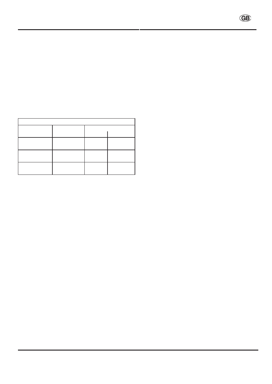
SETTING TABLE ‘SE 81 SIC’
GAS
SPEED
LIMITS
bottom
top
CO (in %)
idling
1.25
1.50
3.500 g/m
0.30
0.60
CO
2
(in %)
idling
12
14
3.500 g/m
13
15
HC (in ppm)
idling
100
150
3.500 g/m
20
60
5. SETTING PROCEDURE FOR REGULATORS
TYPE ‘SE 81 SIC’
without exhaust gas analyser (Fig. 1)
5.1 CATALYSED CAR
See point 4.1 without gas analyser check.
5.2 INJECTION AND CARBURETTED CAR
The first step is to adjust peak speed:
• take the engine to approximately 3,500 r.p.m.
and turn the peak speed regulator located
between the regulator and the mixer clockwise
until you notice a fall in engine speed due to the
mixture getting leaner; then turn this same screw
very slowly anticlockwise until there is an increase
in engine speed; at this stage it is not necessary
to turn the screw further anticlockwise since there
would only be greater consumption and no
increase in efficiency.
The second step is to adjust idling speed:
• with the engine running, turn the Idle speed
setting screw (E) (clockwise it decreases,
anticlockwise it increases) until an optimum idling
Sensitivity setting
speed is obtained which is also to be checked
after the road test.
Having regulated idling and peak speeds, carry
out a test on the road.
6. SENSITIVITY SETTING PROCEDURE FOR
REGULATORS TYPE ‘SE 81 SIC’ (Fig. 1)
The regulators are already set in-house by the
manufacturer. If problems arise, such as idle
speed instability or acceleration gap, please check
the degree of regulator sensitivity.
The setting screw (G) is not used for setting idle
speed but simply to adjust the regulator sensitivity.
By unscrewing it you reduce the spring load on the
2nd stage lever while by tightening it you increase
the spring load on the 2nd stage lever towards
closing.
In particular, since the idle speed flow is
separated from the peak speed one, shifting from
idle to peak speed should take place without
‘carburation gaps’; such gaps may occur, above
all, during too slow accelerations (too tightened
screw); at the same time the regulator should
remain tight without any gas leakage every time
the engine is turned off (too loose screw).
In order to set sensitivity as required do as
follows:
1)
Remove the tube which conveys gas from
the gas outlet connector to the mixer (C);
2)
Tighten the sensitivity screw (G);
3)
Disconnect the blue wire from the plus
contact of the idle speed solenoid valve (F)
and connect the same wire to the plus
contact of the battery ( in order to fill with gas
the regulator);
4)
Make a bubble with soap water on the gas
outlet connector (C) and loosen the screw
(G) until the gas starts coming out of the
regulator and inflates the bubble;
5)
From the time gas starts coming out of the
regulator, tighten screw (G) again until no
more gas leaks. From the moment that no
more gas leaks, tighten the screw another
half turn to be sure that it closes perfectly;
6)
Connect again the blue wire to the plus
contact of the idle speed solenoid valve (F);

LANDI RENZO S.p.A.
‘SE 81 SIC’ LPG REGULATORS INSTALLATION AND ADJUSTMENT MANUAL
10 / 19
Sensitivity setting
Maintenance
7)
Place the cap on the sensitivity screw (G) in
order to avoid accidental or intentional
changes in its setting.
Another less sensitive but more rapid system for
sensitivity adjustments is as follows:
1)
Fully tighten the sensitivity screw (G);
2)
Turn the engine on and set idle speed by
means of screw (E) until the maximum CO
2
level is attained;
3)
Slowly loosen the screw (G) until a marked
change (reduction) in the CO
2
level is
reached;
4)
From the time that this CO
2
change is
observed, tighten the screw (G) until the CO
2
value is the same as in item 2.
5)
Place the cap on the sensitivity screw (G) in
order to avoid accidental or intentional
changes in its setting.
6)
Check that no acceleration gaps are
observed while slowly accelerating.
After the first 500 / 1.000 Km check regulator
sensitivity.
7. MAINTENANCE WORK ON THE SYSTEM
To get the best out of LPG fuel, the engine must
be tuned and regularly serviced, both as regards
the mechanical and the electrical parts. In addition
to the routine maintenance required by the vehicle
manufacturer, it is recommended:
• every 15,000 km check/replace the air filter,
change the spark plugs, check the exhaust gas
with an analyser, check the efficiency of the
electrical system (check there is no oxide
formation in the connections);
• every 30,000 km check the valve clearance,
check lambda probe efficiency (for cars with a
catalytic converter); with the bleed plug, check
there is no oil or other residues inside the
regulator;
• every 100,000 km, if malfunctioning occurs,
carry out a general overhaul of the system using
our product overhaul kits, which are support of
instructions showing the methods to follow.
Using spark plugs with a colder heat rating, it is
wise to check that the distance of the electrodes is
never greater than 1 mm.
It is advised to increase the valve clearance by
0.05 mm with respect to the specifications for
Maintenance
petrol
operation
provided
by
the
vehicle
manufacturer.
Having installed the LPG conversion system, it is
natural to travel as many kilometres as possible
with this fuel: however, so as not to prejudice the
correct operation of the original petrol system and
fuel pump, it is advised to travel 2 - 3 km on petrol
at least every 200 - 300 km (example at each LPG
refuelling)
Date, descriptions and illustrations are indicatory.
LANDI RENZO S.p.A. reserves the right to
improve or modify them without prior notification.
Wyszukiwarka
Podobne podstrony:
GPL Landi Renzo MultiValvola
GPL Landi Renzo MultiValvola
Landi Renzo LCS z emulatorem
Landi Renzo LCS
landi renzo omegas opis parametrów
Landi Renzo Omegas Schemat montażu
GPL Landi Renzo MultiValvola
Renzo Allegri Cuda ojca Pio
Pritzker 1998 Renzo Piano bio
Allegri Renzo Cuda ojca Pio
Landi
Pritzker 1998 Renzo Piano essay
więcej podobnych podstron