
Initial Print Date: 12/04
Table of Contents
Subject
Page
Antenna/Radio Tuner with Diversity (AVT) . . . . . . . . . . . . . . . . . . . . . . . . .4
Antenna System . . . . . . . . . . . . . . . . . . . . . . . . . . . . . . . . . . . . . . . . . . . . . . . .5
Rear Window . . . . . . . . . . . . . . . . . . . . . . . . . . . . . . . . . . . . . . . . . . . . . . . .6
Antenna Diversity Unit (FM) . . . . . . . . . . . . . . . . . . . . . . . . . . . . . . . . . . .6
Antenna Amplifier (FM) . . . . . . . . . . . . . . . . . . . . . . . . . . . . . . . . . . . . . . .7
Antenna Amplifier (AM) . . . . . . . . . . . . . . . . . . . . . . . . . . . . . . . . . . . . . . .7
Network Master . . . . . . . . . . . . . . . . . . . . . . . . . . . . . . . . . . . . . . . . . . . . . .8
Audio Master . . . . . . . . . . . . . . . . . . . . . . . . . . . . . . . . . . . . . . . . . . . . . . . .9
Output of Audio Signals . . . . . . . . . . . . . . . . . . . . . . . . . . . . . . . . . . . . .10
Connection Master . . . . . . . . . . . . . . . . . . . . . . . . . . . . . . . . . . . . . . . . . .10
Basic Hi-Fi Amplifier . . . . . . . . . . . . . . . . . . . . . . . . . . . . . . . . . . . . . . . . . . .11
LOGIC 7 Hi-Fi Amplifier (Part of optional sound package) . . . . . . . . . .12
Speakers . . . . . . . . . . . . . . . . . . . . . . . . . . . . . . . . . . . . . . . . . . . . . . . . . . . .15
Audio CD Changer . . . . . . . . . . . . . . . . . . . . . . . . . . . . . . . . . . . . . . . . . . . .16
E65 Audio System
Revision Date:

2
E65 Audio System
E65 Audio System
Model: E65/E66
Production: All
After completion of this module you will be able to:
• Explain how audio signals are transported in the E65
• Describe the functions of the ASK
• Recognize the component layout of the audio system in the E65
Introduction
On previous vehicle models, the radio was always controlled by an integrated control unit.
This control unit included the tuner, cassette deck, amplifier, display and the operating
unit.
The radio could be equipped as an Hi-Fi audio system by adding further components
(CD changer) or boosters (Digital Signal Processor etc.). Because of the increasing num-
ber of functions in a radio and the limited area available in the standard radio chassis, new
solutions had to be found for the radio control unit.
In the E65, the radio control unit is no longer in a single module. The audio system has
distributed functions which are integrated in various control units, e.g. the display and
operating function.
The radio is operated via the Controller in the center console, the display is produced in
the Control Display located in the instrument panel and the audio signals are controlled in
the ASK.
There are two audio systems available for the E65 from the start of production: A basic
Hi-Fi and the optional LOGIC 7 Hi-fi.
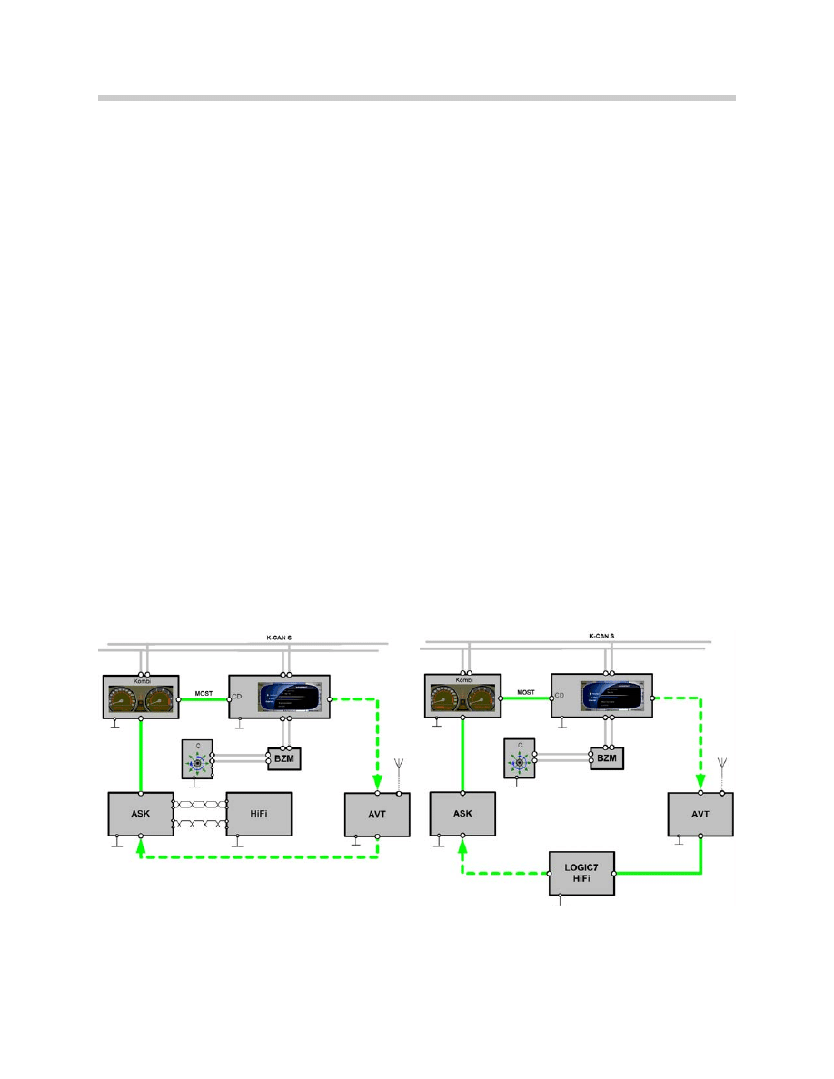
System Diagram
Block diagram of the basic E65 audio systems.
3
E65 Audio System
E65 Audio System (Hi-Fi)
E65 Audio System (Logic 7)
Components
Antenna/Radio Tuner with Diversity (AVT)
The E65 tuner is different from previous radios. The tuner is actually a control unit with a
MOST port and is placed in a different location than the radio.
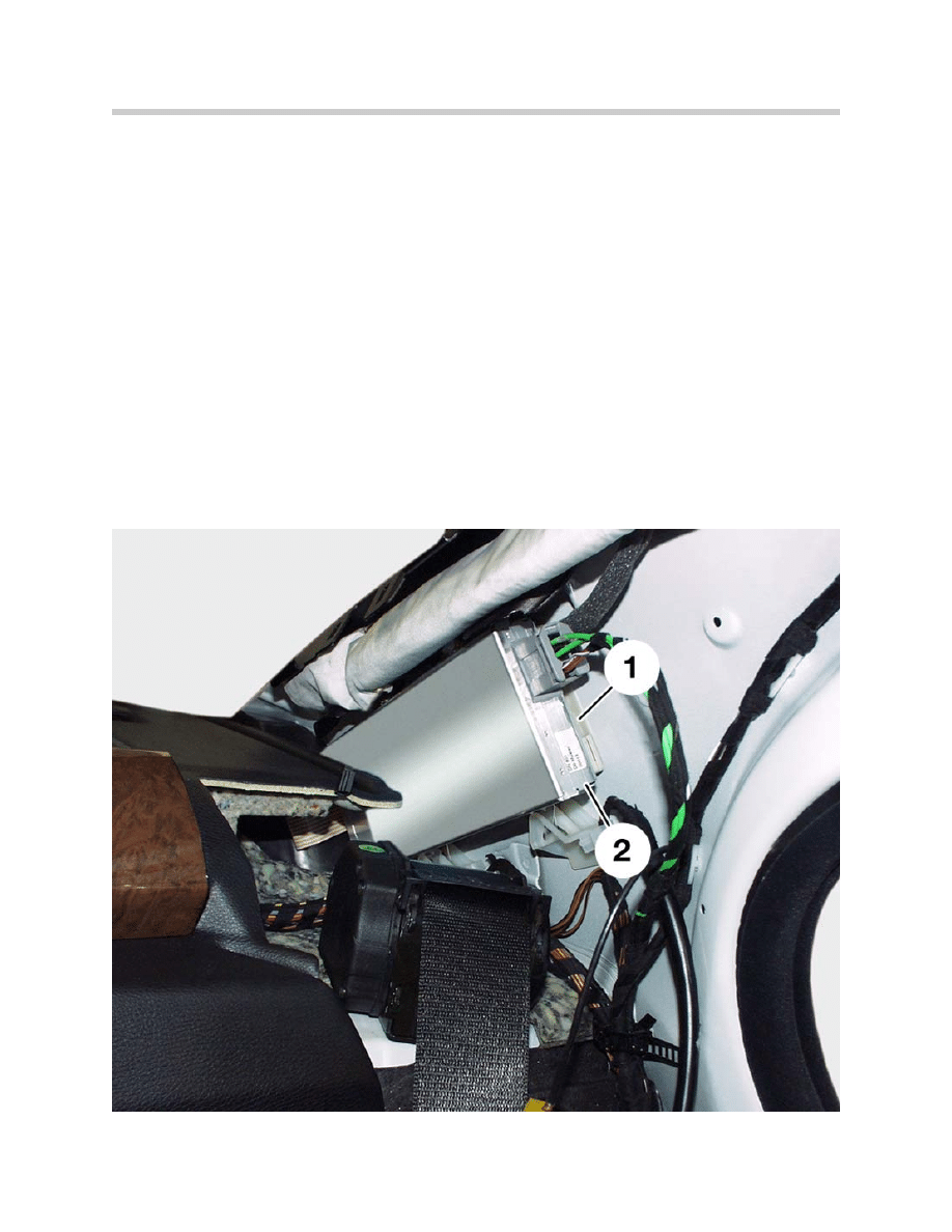
The tuner (2) is now located close to the antennas. The installation location of the anten-
na tuner is in the rear left C pillar. Due to the direct connection of the antenna diversity
(1), no antenna amplifier is needed on the left-hand side.
On the right-hand side, there is an antenna amplifier which is linked via a coaxial cable to
the diversity unit. The tuner provides the power supply to the antenna diversity and the
antenna amplifier.
The digital audio signals are transmitted to the ASK via the MOST, therefore there is no
antenna coaxial cable. This avoids signal losses and interference.
4
E65 Audio System
AVT in Left C-pillar
The tuner used on U.S. E65s is a world tuner which can receive long wave (LW), medium
wave (AM), short wave (SW) and frequency modulation (FM), as well as traffic and weath-
er forecast information (US). In the U.S. weather forecast information is transmitted on 7
different frequencies 24 hours a day.
The single tuner is set for all country variants, with the exception of the ECE. It corre-
sponds to the former Business Radio.
Antenna System
The antenna for radio and remote control services (FBD) on the E65 are located in the
rear window. They include an AM antenna for LW, MW, and SW and 4 FM aerials for VHF
reception. The FBD frequency for U.S. vehicles is 868.4MHz
5
E65 Audio System
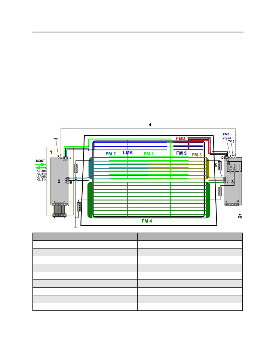
Index
Description
Index
Description
1
Antenna tuner
FM3
Third FM antenna
2
Antenna diversity
FM4
Fourth FM antenna
3
Antenna amplifier
FM5
FM antenna for traffic announcements (Japan)
4
Coaxial cable
FBD
Antenna for remote control services
5
Suppressors are integrated into the harness
PM
Power module
6
Filter trap
KL30
Power supply
LMK
AM antenna for long, middle and short waves
KL31
Ground
FM1
First FM antenna
UANT
Power supply for antenna modules
FM2
Second FM antenna

The antennas are switched by the diversity module, which is directly located on the tuner
and is connected to it by an 8-pin ribbon cable.
The antennas for telephone and navigation are located in a separate shark fin antenna on
the roof.
The advantages of the new E65 antenna system are the following:
• Powerful AM (LMK) antenna.
• FM diversity available in the basic audio system.
• High FM diversity performance due to 4 switchable antennas: FM 1-4.
• Modular application of basic system on many system variants, e.g. radio, TV, FBD.
• The antenna system (tuner) has diagnosis capability.
The antenna system is made up of the following components:
Rear Window
The rear window is made laminated safety glass (VSG) with infrared coating (IR).
The glass thickness is 4 mm. The antenna consist of leads 0.4 mm wide. The rear win-
dow is partitioned into three sections. The first part includes the AM and FM 5/FBD
antennas. The second part includes the FM 1, FM 2 and FM 3 antenna. The lower half
includes the FM 4 antenna.
The rear screen defroster uses the central and lower panels of the FM antenna. The
heating power is approximately. 300 W.
Antenna Diversity Unit (FM)
The antenna diversity is installed in the left C pillar, together with the tuner. It is connect-
ed to the tuner by an 8-pin ribbon cable.
The ribbon cable is used to transmit the operating voltage and the switching signals
DIAGNOSIS, CONTROL, LEVEL, AUDIO from tuner to diversity. The HF signal is trans-
ferred from diversity to the tuner.
The antenna diversity is used to define the best antenna signal and controls the
changeover and the output of the antenna signal on the HF output.
6
E65 Audio System
Antenna Amplifier (FM)
The antenna amplifier in the RH C-pillar is associated to antennas FM 3-4 and to the
FBD antenna. The antenna amplifier is linked by a coaxial cable to the antenna diversity
unit.
The FM antennas are switched over by a control signal, fed via the coaxial cable.
Antenna Amplifier (AM)
The AM amplifier used for LW, MW, and SW ranges, is located in the diversity unit in the
LH C-pillar.
7
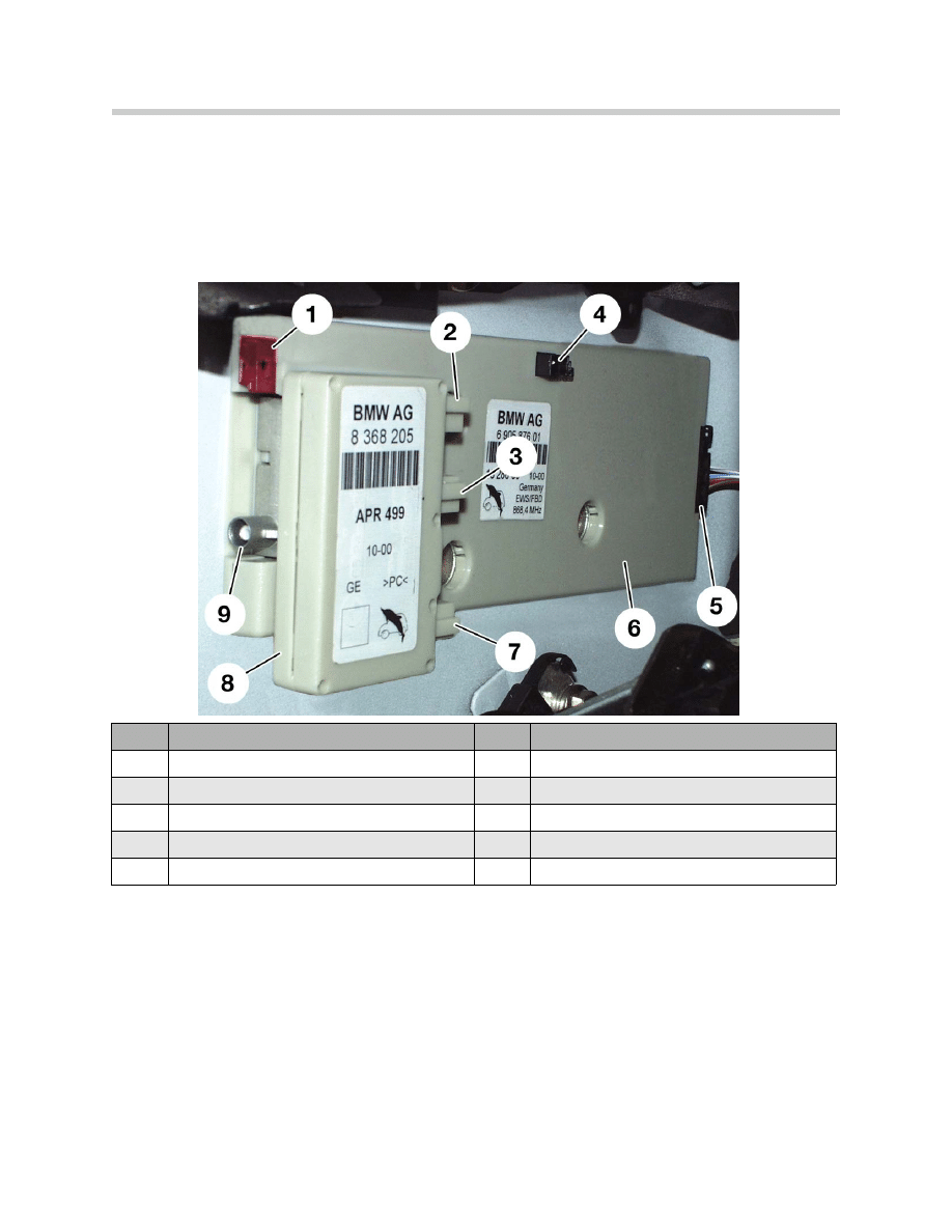
E65 Audio System
Index
Description
Index
Description
1
FBD Antenna connection
6
Antenna amplifier
2
Power input for the rear defroster
7
Read defroster grid output connection
3
Rear defroster grid output connection
8
Filter trap circuit for rear defroster
4
Antenna connection (FM1-FM5)
9
Coax connection to antenna diversity unit
5
Wiring harness connection (8-pin)
Audio System Controller
In the past, each system used its own output media (e.g. gong, dual cone speakers etc)
which generated a number of different sounds in the car. It was often not possible to
achieve coordination between these sounds or at best, it could be done only in particular
cases.
This created situations where acoustic information for other sources had to be sup-
pressed, otherwise the driver would have been faced with a confusing mix of acoustic
signals.
On the E65, a control unit has been developed to control, coordinate and generate
acoustic signals according to priority: the Audio System Controller, (ASK).
The Audio System Controller (ASK) has three main functions:
• Network master
• Audio master
• Connection master
Network Master
The ASK performs the role of network master for the MOST bus. The functions of the
network master are the following:
•
Wake-up, initialization, power-down - The network master wakes up the bus
and has the task of achieving an orderly initialization of the network. The ASK can
operate with KLR off. To turn it on, push in the volume/ON/OFF knob. Adjustments
and control is carried out by using the Controller and Control Display. Another task
of the network master is to control the power-down process. Each power - down is
initiated and started by the ASK.
•
Configuration control - The network master detects the exact system configura-
tion each time that the network is started and compares it to the stored coded con-
figuration.
8
E65 Audio System

• Control of the network operation - The network master controls the MOST trans-
ceiver of the slave equipment for correct operation. The equipment which is not
operating properly will be released by a reset or switched to low power mode so that
they do not affect bus communication.
• Fault code memory - The network master includes the fault code memory of the
MOST network. It stores all the faults occurring during the network operation as well
as deviations from the nominal configuration.
Audio Master
As audio master, the ASK has the task to collect and process all the audio signals of the
vehicle and to distribute them to their destinations.
The ASK controls all the acoustic requests from the Control Display. The changes in the
level of a signal is not sudden, but smooth, e.g. during suppression, insertion and fading
out or temporary suppression of the signal at the destination: Because of this, a high-
quality acoustic sound is obtained.
The ASK also assumes the generation and preparation of different acoustic signals, e.g.
PDC signals and warnings. In the event of a request for a warning or caution signal from
a control unit, the ASK provides a clean acoustic change of the signals.
• Audio data - All audio data from any control unit are converted by the ASK into digital
audio AF format at a sampling rate of 44.1 KHz.
• Categorization of audio sources - All possible audio sources are divided into different
groups according to priority. Warning signals have priority over any other audio
source. Mixing of lower priority audio signals (e.g. navigation, radio) is possible.
• Generation of acoustic gongs - These are acoustic alarm signals which help the dri-
ver perceive sounds according to a system. The different sounds, requested by the
different control units, (e.g. gongs, PDC,etc.), must be generated only in association
with a visual indication. These come from the instrument cluster and the Control
Display.
The following sounds can be generated in the ASK.
• Beeping for the PDC.
• Various Check Control and warning gongs.
9
E65 Audio System

Output of Audio Signals
The output of audio signals occurs under the following conditions:
• Two gong signals are never output simultaneously.
• It is possible to generate a maximum of 3 signals at the same time.
• If the input includes a fourth signal, the signal at the lowest priority is muted.
• When issuing the 3 higher priority signals, the entertainment source is suppressed
(radio). If the entertainment source is a CD, it is stopped and switched off. When the
CD is reactivated, it restarts from the point where it was stopped.
Examples of audio output:
• Radio - The radio plays in the background, the PDC is active and a navigation
message is output. If a gong request comes, the radio is muted and the gong is
generated.
• Telephone - When the hands-free function is activated the loudspeakers are muted.
Gongs are mixed as required according to their priority. The Speech Processing
System is not active when the hands-free function is used.
• Speech Processing System - When the voice processing system is activated, a gen-
eral mute suppresses the loudspeakers. Gongs are mixed as required according to
their priority. The hands-free operation and the navigation messages interrupt the
Speech Processing System.
Connection Master
As connection master, the ASK must provide channels to the equipment connected to
the bus and distribute the audio signals on the outputs (loudspeakers).
The connection master also controls the basic Hi-Fi or the LOGIC 7 Hi-Fi amplifiers.
10
E65 Audio System
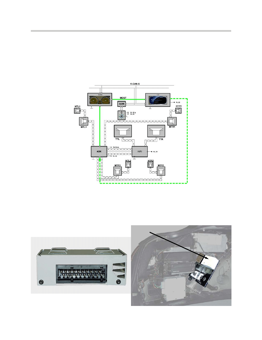
Basic Hi-Fi Amplifier
A hi-fi system is offered as standard equipment and is characterized by vehicle-specific
tuning to the interior (equalizing) with balanced acoustics.
The basic signals delivered by the ASK are amplified in the hi-fi amplifier equipped with
bridge end stages. The output power is 40 W per channel. Total system output is 180
watts.
The hi-fi amplifier is controlled by the ASK. The medium-range loudspeakers and the
tweeters are directly controlled by the ASK. The large sub-woofers underneath the driver
and passenger seats are driven by the amplifier.
The hi-fi amplifier has no diagnosis capability.
11
E65 Audio System
Location of hi-fi amplifier
in trunk
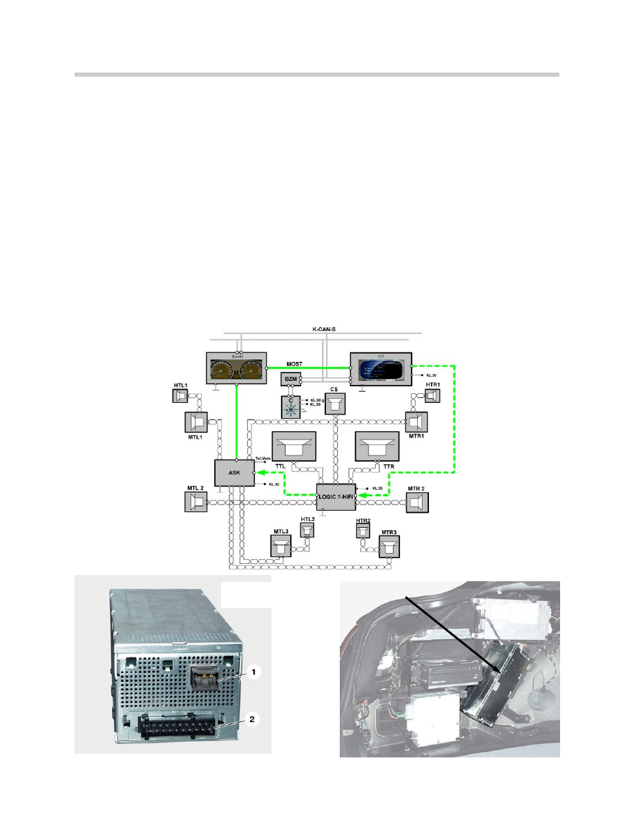
LOGIC 7 Hi-Fi Amplifier (Part of optional sound package)
To satisfy customers with the more demanding requirements for a low-distortion playback
even at high levels and non-linear frequencies (e.g. amplified low frequencies), it is neces-
sary to provide a sufficient output power to control the loudspeaker.
For these reasons, a LOGIC 7 hi-fi system with Surround Sound and 7-band equalizer
was developed. The main differences from the hi-fi amplifier are the following:
• Active MOST bus components.
• Complete control via the software.
• Extended features versus the hi-fi system.
• Higher output power in the low-frequency range.
• More channels available to control additional loudspeakers.
• Diagnosis capability.
12
E65 Audio System
Location of Logic 7
amp in trunk
1. MOST connector
2. 20-pin connector

The LOGIC 7 hi-fi amplifier includes a MOST bus connection, to produce all audio and
control signals in digital form. A digital / analog converter converts the audio signals and
amplifies them in the final stages.
The output power of the mid-range loudspeaker is 40 W and the woofer is 70 W. Total
system output is 420 watts.
Additional features are the central front loudspeaker in the instrument panel, the mid-
range speakers in the rear doors and the tweeters under the rear shelf.
Besides the known functions like volume, fader, balance, treble, bass and GAL (speed-
sensitive radio volume control) the two amplifiers hi-fi and LOGIC 7 hi-fi achieve the fol-
lowing functions:
• 7-band equalizer (LOGIC 7 hi-fi only) - The frequency ranges can be adjusted indi-
vidually by the customer. The adjustment is performed by the Controller and the
Control Display on the ASK.
• Surround Sound (LOGIC 7 hi-fi only) - Can be enabled / disabled by the customer.
Surround Sound is the use of at least 5 channels in the interior. With an additional
loudspeaker in the front between the left and the right channel, a true spatial sound
can be obtained.
The following functions cannot be controlled by the customer, but they are achieved in
the amplifier software:
•
Level adaptation - Switching between different audio sources (e.g. CC-CD)
should produce no change in volume. For this purpose, all levels in ASK are
processed on a standard level.
•
Loudness - To improve reception at a low-volume setting, the low frequencies are
slightly amplified.
•
Vehicle-specific equalizing - Tuning of the acoustics according to the interior of
the vehicle.
•
Speed-dependent equalizing (LOGIC 7-hi-fi only) - Adjustment of the
acoustics to increasing noise emission from moving vehicles.
•
Dynamic compression - In a moving vehicle, the usable dynamics is limited in the
upper range by the output power of the amplifier and the load characteristics of the
loudspeaker. For this reason, a speed-dependent dynamics reduction must be per-
formed.
•
Frequency-dependent delay (LOGIC 7 hi-fi only) - The frequency-dependent
delay is used to introduce time corrections on the individual speaker units. This
ensures that the audio signals are sent simultaneously to all speaker units.
13
E65 Audio System
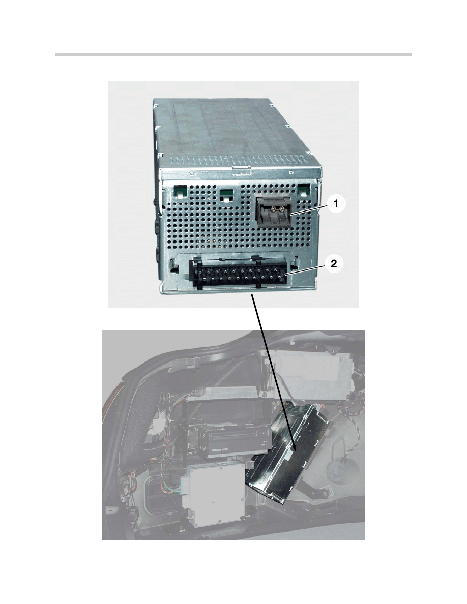
14
E65 Audio System
1. MOST Connector
2. 20-pin connector
Location of LOGIC 7
amplifier in trunk
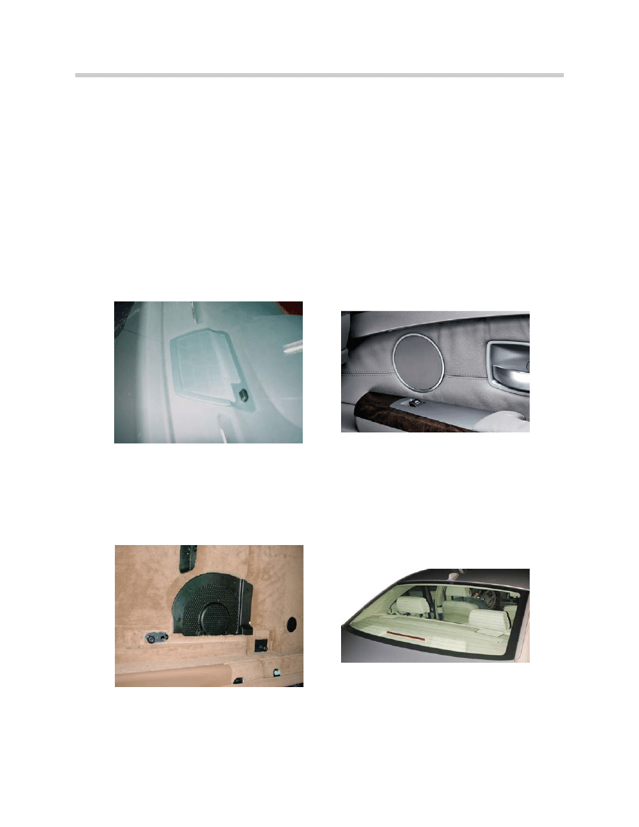
Speakers
The Basic Hi-Fi of the E65 comes equipped with 10 speakers. If the LOGIC 7 system is
ordered the vehicle has 13 speakers. The speaker locations are as follows:
• 100mm mid-range and 44mm high range speaker in each front door. Rear doors
have mid-range speakers if equipped with LOGIC 7.
• 100mm center channel mid-range speaker located in the center of the instrument
panel speaker if equipped with LOGIC 7.
• 210mm sub-woofers located underneath the driver and passenger seats.
• Two 100mm mid-range and two 44mm high-range speakers located in rear shelf.
15
E65 Audio System
100mm center channel mid-range speaker
located in the instrument panel (with Logic7).
210mm sub-woofers located underneath the
driver and passenger seats.
Two 100mm mid-range and two 44mm high-
range speakers located in the rear shelf
100mm midrange and 44mm high range
speakers in each front door.
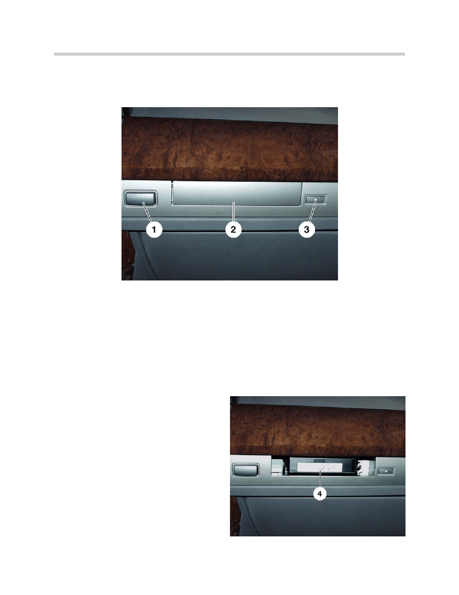
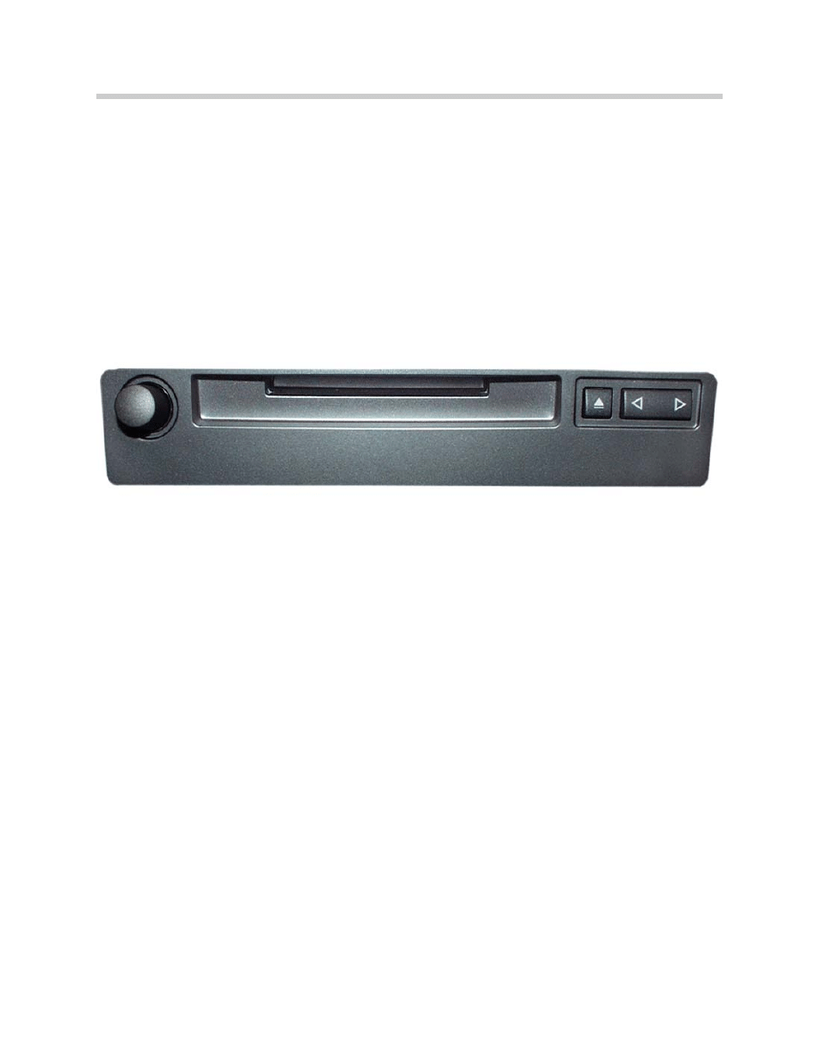
Audio CD Changer
The audio CD changer on the E65 has the same features and mechanical structure as its
equivalent in E38 / E39, it is produced by Alpine.
This is a 6-way-changer with magazine (4). It is installed on the passenger side in the
instrument panel, behind a decorative strip. If you press the eject key (3) and use the
powered flap control, you can control the insertion and removal of the magazine from
the driver and the passenger side.
A new feature of the CD changer is the optical connection to the MOST bus. The CD
changer is controlled via the MOST bus interface and sends its digital audio signals
over it.
The audio signals are sent to the ASK which transmits them via the amplifier and then
to the loudspeakers.
To operate the CD changer, you can use
the following options:
• Controller and Control display
• ASK and MFL
• Voice input
The CD changer has diagnostic capabilities
in the Diagnosis Program via MOST.
16
E65 Audio System

Classroom Exercise - Review Questions
1.
Which device in the audio system is responsible for receiving the radio signals and
converting them to digital signals? How are those signals transported?
2.
Which control unit is responsible for producing the audio signals? How many
signals may be output at one time?
3.
From what terminal (KL) is the audio system operational?
4.
What other component shares the Network Master responsibility with the ASK?
5.
Describe the system differences between the Basic Hi-Fi and the LOGIC 7.
17
E65 Audio System
Document Outline
- Main Menu
- Intro to Advanced Body Electronics
- E65 Power Module
- E65 Car Access System
- E65 Instrument Cluster
- E65 iDrive Driving Area
- E65 iDrive Comfort Area
- E65 Audio System
- E65 Navigation System
- E65 Telephone
- E65 Speech Processing System
- E65 Central Body Electronics
- E65 Remote Control Services
- E65 Automatic Trunk Lid Lift
- E65 Wiping Washing
- E65 Seat, Mirror, Steering Wheel
- E65 Lighting Systems
- E65 Driveaway Protection
- E65 Park Distance Control
- E65 Active Cruise Control
- Voltage Supply and Bus Systems
- 5 & 6 Series Body Electronics
- E60 Driver Information Systems
- E60 Communication Systems
- Car Communication Computer
- Head-Up Display
- Glossary
Wyszukiwarka
Podobne podstrony:
09 E65 Audio System
Navigation and Audio System
diagnostics Audio System
Audio System for Built In Type Amplifier
Audio System for Separate Type Amplifier
16 E70 Audio Systems
93ZJ Secc 8F Audio Systems
04a E65 Central Body Electronics
07b E70 Audio Systems
07 E70 Audio Systems WB
96ZJ 8F AUDIO SYSTEMS
10 E65 Navigation System
06 E65 Lighting Systems
04b E65 Navigation System
AUDIO SYSTEM SECTION 9F 17
więcej podobnych podstron