
SECTION : 9F
AUDIO SYSTEMS
CAUTION : Disconnect the negative battery cable before removing or installing any electrical unit or when a tool
or equipment could easily come in contact with exposed electrical terminals. Disconnecting this cable will help
prevent personal injury and damage to the vehicle. The ignition must also be in LOCK unless otherwise noted.
TABLE OF CONTENTS
SPECIFICATIONS
9F–1
. . . . . . . . . . . . . . . . . . . . . . . . . .
FASTENER TIGHTENING SPECIFICATIONS
9F–1
.
SCHEMATIC AND ROUTING DIAGRAMS
9F–2
. . . . .
AUDIO SYSTEM CIRCUIT
9F–2
. . . . . . . . . . . . . . . . . .
DIAGNOSIS
9F–3
. . . . . . . . . . . . . . . . . . . . . . . . . . . . . . . .
STEREO CASSETTE AM/FM RADIO
9F–3
. . . . . . . .
SPEAKERS
9F–5
. . . . . . . . . . . . . . . . . . . . . . . . . . . . . . .
ANTENNA
9F–6
. . . . . . . . . . . . . . . . . . . . . . . . . . . . . . . .
MAINTENANCE AND REPAIR
9F–8
. . . . . . . . . . . . . . .
ON–VEHICLE SERVICE
9F–8
. . . . . . . . . . . . . . . . . . . . .
STEREO CASSETTE AM/FM RADIO
9F–8
. . . . . . . .
FRONT DOOR SPEAKERS
9F–9
. . . . . . . . . . . . . . . . .
TWEETER SPEAKERS
9F–10
. . . . . . . . . . . . . . . . . . .
REAR SPEAKERS (NOTCHBACK)
9F–10
. . . . . . . . .
REAR SPEAKERS (HATCHBACK)
9F–11
. . . . . . . . . .
MAST ANTENNA
9F–12
. . . . . . . . . . . . . . . . . . . . . . . . .
ROOF ANTENNA
9F–13
. . . . . . . . . . . . . . . . . . . . . . . .
POWER ANTENNA MAST(NOTCHBACK)
9F–13
. . .
POWER ANTENNA MOTOR (NOTCHBACK)
9F–14
COMPACT DISC CHANGER
9F–15
. . . . . . . . . . . . . . .
GENERAL DESCRIPTION AND SYSTEM
OPERATION
9F–17
. . . . . . . . . . . . . . . . . . . . . . . . . . . . .
AUDIO SYSTEMS
9F–17
. . . . . . . . . . . . . . . . . . . . . . . .
AUDIO SECURITY SYSTEM
9F–17
. . . . . . . . . . . . . . .
FRONT AND REAR SPEAKERS
9F–17
. . . . . . . . . . .
TWEETER SPEAKERS
9F–17
. . . . . . . . . . . . . . . . . . .
MAST ANTENNA
9F–17
. . . . . . . . . . . . . . . . . . . . . . . . .
POWER ANTENNA
9F–17
. . . . . . . . . . . . . . . . . . . . . . .
ROOF ANTENNA
9F–17
. . . . . . . . . . . . . . . . . . . . . . . .
TAPE PLAYER AND CASSETTE CARE
9F–17
. . . . .
COMPACT DISC CARE
9F–17
. . . . . . . . . . . . . . . . . . .
SPECIFICATIONS
FASTENER TIGHTENING SPECIFICATIONS
Application
N
S
m
Lb–Ft
Lb–In
Antenna Cap Nut
7
–
62
Antenna Motor Nuts
7
–
62
Audio System Bolts
4
–
35
CD Changer Nuts
7
–
62
Mast Antenna Base Nut
4
–
35
Front Door Speaker Screws
4
–
35
Rear Speaker Screws
4
–
35
Roof Antenna Nut
10
–
89

9F – 2
I
AUDIO SYSTEMS
DAEWOO V–121 BL4
SCHEMATIC AND ROUTING DIAGRAMS
AUDIO SYSTEM CIRCUIT

AUDIO SYSTEMS 9F – 3
DAEWOO V–121 BL4
DIAGNOSIS
STEREO CASSETTE AM/FM RADIO
Cassette AM/FM Radio Inoperative
Step
Action
Value(s)
Yes
No
1
Check fuses EF1, F9, and F10.
Are fuses EF1, F9, and F10 blown?
Go to Step 2
Go to Step 3
2
1. Check for a short circuit and repair if neces-
sary.
2. Replace the blown fuses.
Is the repair complete?
System OK
3
1. Use a voltmeter to test for battery voltage at
fuses EF1 and F10.
2. Turn the ignition ON and test for battery volt-
age at fuse F9.
Does the battery voltage match the specified value
at fuses EF1, F9, and F10?
11–14 v
Go to Step 5
Go to Step 4
4
Repair the power supply circuit to the fuses.
Is the repair complete?
System OK
5
1. Disconnect the radio electrical connector.
2. Turn the ignition ON.
3. Use a voltmeter to test for battery voltage at
the radio connector terminals 4 and 5.
Does the battery voltage match the specified value
at both terminals?
11–14 v
Go to Step 7
Go to Step 6
6
Repair the open circuit between the radio connector
and the fuse.
Is the repair complete?
System OK
7
Use an ohmmeter to test the ground circuit at the ra-
dio connector terminal 14.
Does the resistance match the specified value?
0–0.5
W
Go to Step 9
Go to Step 8
8
Repair the open ground circuit between the radio
connector and ground G105.
Is the repair complete?
System OK
9
Replace the radio.
Is the repair complete?
System OK
Cassette Player Inoperative, AM/FM Functions OK
Step
Action
Value(s)
Yes
No
1
Verify the customer complaint.
Does the cassette player destroy tapes?
Go to Step 5
Go to Step 2
2
Using a good–quality tape, determine whether the
cassette player performs poorly or is inoperative.
Does the cassette player perform poorly?
Go to Step 5
Go to Step 3
3
Check the cassette player for obstructions behind
the tape door.
Is an obstruction found?
Go to Step 4
Go to Step 8

9F – 4
I
AUDIO SYSTEMS
DAEWOO V–121 BL4
Step
No
Yes
Value(s)
Action
4
Check to see if the obstruction can be removed us-
ing gentle force.
Is the obstruction removed?
Go to Step 5
Go to Step 6
5
Clean the cassette player head, the capstan, and the
drive system.
Does the tape play properly?
Go to Step 7
Go to Step 6
6
Replace the radio.
Is the repair complete?
System OK
7
Check the cassette player for normal operation.
Is the repair complete?
System OK
8
Advise the owner of a defective or worn tape.
Is the repair complete?
System OK
AM Does Not Work, FM and Cassette OK
Step
Action
Value(s)
Yes
No
1
Replace the radio.
Is the repair comlpete?
FM Radio Does Not Work, AM and Cassette OK
Step
Action
Value(s)
Yes
No
1
1. Unplug the antenna cable from the antenna.
2. Connect the test antenna to the antenna cable.
3. Check the FM radio reception.
Is the FM radio operating properly?
Go to Step 2
Go to Step 3
2
Replace the antenna.
Is the repair complete?
System OK
3
1. Remove the radio from the instrument panel.
2. Unplug the antenna cable from the radio.
3. Plug the test antenna into the radio.
4. Check the FM radio reception.
Is the FM radio operating properly?
Go to Step 4
Go to Step 5
4
Replace the antenna cable between the radio and
the antenna.
Is the repair complete?
System OK
5
Replace the radio.
Is the repair complete?
System OK

AUDIO SYSTEMS 9F – 5
DAEWOO V–121 BL4
SPEAKERS
Front Speakers Distorted or Inoperative, Rest of Audio System OK
Step
Action
Value(s)
Yes
No
1
1. Turn the ignition and the radio ON.
2. Check for distorted or inoperative front speak-
ers using the fader and the balance controls
with all of the sources (AM, FM, tape, CD).
Are the front speakers distorted?
Go to Step 2
Go to Step 4
2
Check the speaker and the door area for damage,
rattles, or vibration.
Is there anything loose or in the way of the speaker
causing the distortion?
Go to Step 3
Go to Step 4
3
Make the necessary repairs to secure the compo-
nent causing the distortion.
Is the repair complete?
System OK
4
1. Remove the front speakers and disconnect the
speaker connector.
2. Using an ohmmeter, test the speaker wires for
a short to ground.
Does the ohmmeter show the specified value?
R
Go to Step 6
Go to Step 5
5
Repair the short circuit between the front speaker
connector and the radio connector.
Is the repair complete?
System OK
6
Substitute a known good speaker for the speaker
causing the distortion.
Is the distortion eliminated?
Go to Step 7
Go to Step 8
7
Replace the speaker.
Is the repair complete?
System OK
8
Replace the radio.
Is the repair complete?
System OK
Rear Speakers Distorted or Inoperative, Rest of Audio System OK
Step
Action
Value(s)
Yes
No
1
1. Turn the ignition and the radio ON.
2. Check for distorted or inoperative rear speak-
ers using the fader and the balance controls
with all the of the sources (AM, FM, tape, CD).
Are the rear speakers distorted?
Go to Step 2
Go to Step 4
2
Check the speakers, the rear deck, and the trunk
area for damage, rattles, or vibration.
Is there anything loose or in the way of the speaker
causing the distortion?
Go to Step 3
Go to Step 4
3
Make the necessary repairs to secure the compo-
nent causing the distortion.
Is the repair complete?
System OK
4
1. Disconnect the rear speakers.
2. Using an ohmmeter, test the speaker wires for
a short to ground.
Does the ohmmeter show the specified value?
R
Go to Step 6
Go to Step 5

9F – 6
I
AUDIO SYSTEMS
DAEWOO V–121 BL4
Step
No
Yes
Value(s)
Action
5
Repair the short circuit between the rear speaker
connector and the radio connector.
Is the repair complete?
System OK
6
Substitute a known good speaker for the speaker
causing the distortion.
Is the distortion eliminated?
Go to Step 7
Go to Step 8
7
Replace the speaker.
Is the repair complete?
System OK
8
Replace the radio.
Is the repair complete?
System OK
ANTENNA
Power Antenna Does Not Work
Step
Action
Value(s)
Yes
No
1
Check fuse EF29.
Is fuse EF29 blown?
Go to Step 2
Go to Step 3
2
1. Check for a short circuit and repair if neces-
sary.
2. Replace the blown fuse.
Is the repair complete?
System OK
3
Use a voltmeter to test for battery voltage at fuse
EF29.
Does the battery voltage match the specified value?
11–14 v
Go to Step 5
Go to Step 4
4
Repair the open power supply circuit to fuse EF29.
Is the repair complete?
System OK
5
Use a voltmeter to test for battery voltage at power
antenna connector terminal 1.
Does the battery voltage match the specified value?
11–14 v
Go to Step 7
Go to Step 6
6
Repair the open circuit between power antenna con-
nector terminal 1 and fuse EF29.
Is the repair complete?
System OK
7
Use an ohmmeter to test the ground circuit at power
antenna connector terminal 2.
Does the resistance match the specified value?
0 – 0.5
W
Go to Step 9
Go to Step 8
8
Repair the open ground circuit between power an-
tenna connector terminal 2 and ground G303.
Is the repair complete?
System OK
9
1. Turn the ignition ON.
2. Turn the radio ON.
3. Use a voltmeter to test for battery voltage at
power antenna connector terminal 3.
Does the battery voltage match the specified value?
11–14 v
Go to Step 10
Go to Step 11
10
Replace the power antenna.
Is the repair complete?
System OK
11
1. Turn the ignition ON.
2. Turn the radio ON.
3. Use a voltmeter to test for battery voltage at
radio terminal 12.
Is the repair complete?
11–14 v
Go to Step 12
Go to Step 13

AUDIO SYSTEMS 9F – 7
DAEWOO V–121 BL4
Step
No
Yes
Value(s)
Action
12
Repair the open circuit between radio terminal 12
and power antenna connector terminal 3.
Is the repair complete?
System OK
13
Replace the audio system.
Is the repair complete?
System OK

9F – 8
I
AUDIO SYSTEMS
DAEWOO V–121 BL4
MAINTENANCE AND REPAIR
ON–VEHICLE SERVICE
STEREO CASSETTE AM/FM RADIO
Removal Procedure
1. Disconnect the negative battery cable.
2. Remove the audio system trim plate screws and
the audio system trim plate.
3. Remove the audio system bolts and the audio sys-
tem.
4. Disconnect the audio system electrical connector
and the antenna cable.
Installation Procedure
1. Connect the audio system electrical connector and
the antenna cable.

AUDIO SYSTEMS 9F – 9
DAEWOO V–121 BL4
2. Install the audio system with the bolts.
Tighten
Tighten the audio system bolts to 4 N
S
m (35 lb–in).
3. Install the audio system trim plate with the screws.
4. Connect the negative battery cable.
5. Enter the security code. Refer to ”Audio Security
Sys–tem” in this section.
FRONT DOOR SPEAKERS
Removal Procedure
1. Disconnect the negative battery cable.
2. Remove the front door trim panel. Refer to section
9G, Interior Trim.
3. Remove the front door speaker screws and the
front door speaker.
4. Disconnect the electrical connector.
Installation Procedure
1. Connect the electrical connector.
2. Install the front door speaker with the screws.
Tighten
Tighten the front door speaker screws to 4 N
S
m (35
lb–in).
3. Install the front door trim panel. Refer to section
9G, Interior Trim.
4. Connect the negative battery cable.

9F – 10
I
AUDIO SYSTEMS
DAEWOO V–121 BL4
TWEETER SPEAKERS
Removal Procedure
1. Disconnect the negative battery cable.
2. Remove the tweeter speaker by prying the tweeter
speaker off of the front door eschutcheon.
3. Disconnect the electrical connector.
Installation Procedure
1. Connect the electrical connector.
2. Install the tweeter speaker by snapping the tweeter
speaker onto the front door eschutcheon.
3. Connect the negative battery cable.
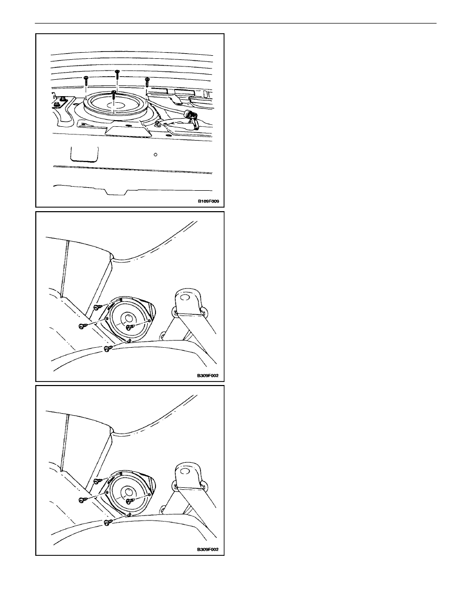
REAR SPEAKERS (NOTCHBACK)
Removal Procedure
1. Disconnect the negative battery cable.
2. Remove the rear seat cushion and the rear seat-
back. Refer to Section 9H, Seats.
3. Remove the right side C–pillar trim panel and the
deck lid sill plate trim cover. Refer to section 9G,
Interior Trim.
4. Disconnect the electrical connector.
5. Remove the screws and the rear speakers.
AUDIO SYSTEMS 9F – 11
DAEWOO V–121 BL4
Installation Procedure
1. Install the rear speakers with the screws.
Tighten
Tighten the rear speaker screws to 4 N
S
m (35 lb–in).
2. Connect the electrical connector.
3. Install the deck lid sill plate trim cover and the right
side C–pillar trim panel. Refer tosection 9G, Interior
Trim.
4. Install the rear seatback and the rear seat cushion.
Refer to Section 9H, Seats.
5. Connect the negative battery cable.
REAR SPEAKERS (HATCHBACK)
Removal Procedure
1. Disconnect the negative battery cable.
2. Remove the rear speaker access cover.
3. Remove the screws and the rear speaker.
4. Disconnect the electrical connector.
Installation Procedure
1. Connect the electrical connector.
Notice : Dissimilar metals in direct contact with each other
may corrode rapidly. Make sure to use the correct fasten-
ers to prevent premature corrosion.
2. Install the rear speaker with the screws.
Tighten
Tighten the rear speaker screws to 4 N
S
m (35 lb–in).
3. Install the rear speaker access cover.
4. Connect the negative battery cable.

9F – 12
I
AUDIO SYSTEMS
DAEWOO V–121 BL4
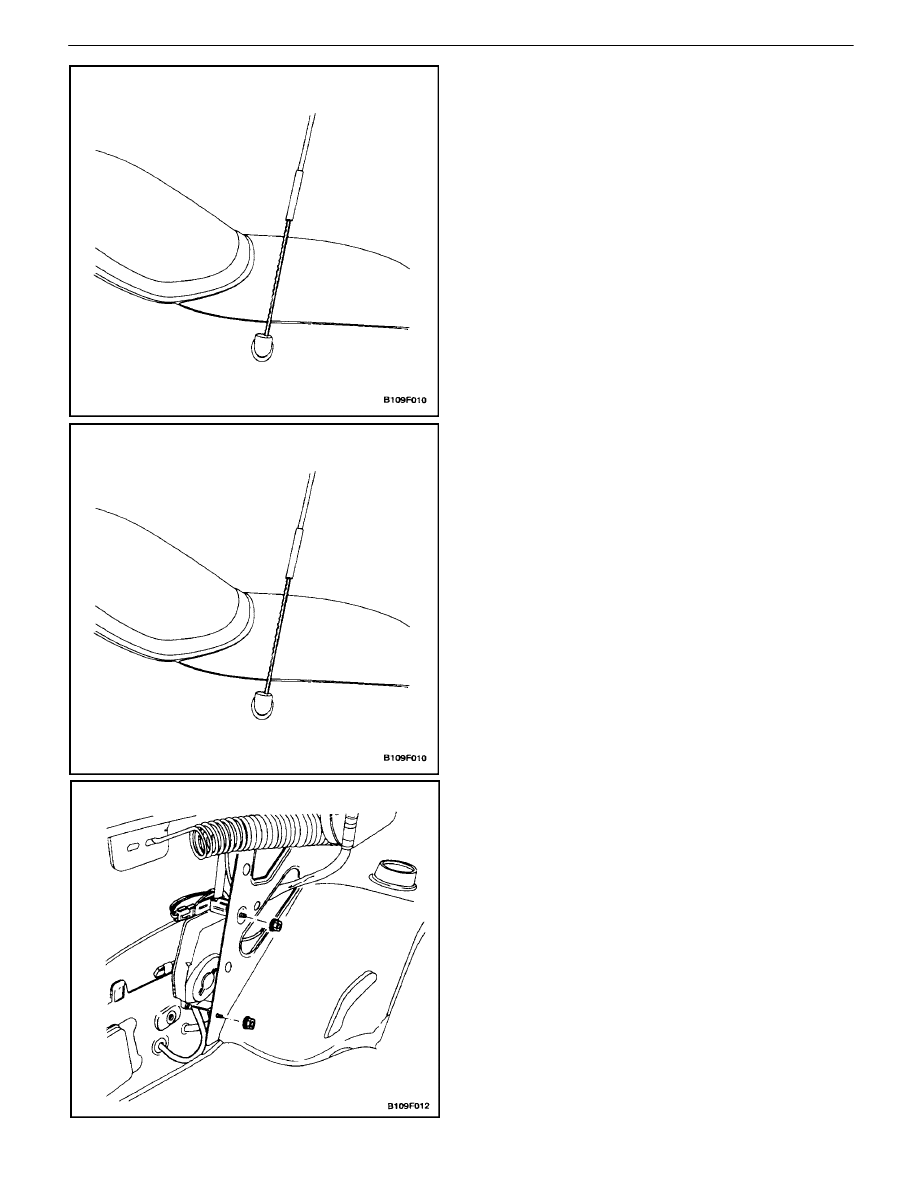
MAST ANTENNA
Removal Procedure
1. Disconnect the negative battery cable.
2. Remove the luggage compartment rear quarter trim
panel. Refer toSection 9G, Interior Trim.
3. Unscrew and remove the mast antenna.
4. Remove the antenna cap nut and the rubber grom-
met.
Installation Procedure
Notice : Dissimilar metals in direct contact with each other
may corrode rapidly. Make sure to use the correct fasten-
ers to prevent premature corrosion.
1. Install the mast antenna base with the nut.
Tighten
Tighten the mast antenna base nut to 4 N
S
m (35 lbin).
2. Connect the antenna cable.
3. Install the rubber grommet and the antenna cap
nut.
Tighten
Tighten the antenna cap nut to 7 N
S
m (62 lb–in).
4. Install the mast antenna.
5. Install the luggage compartment rear quarter trim
panel. Refer toSection 9G, Interior Trim.
6. Connect the negative battery cable.

AUDIO SYSTEMS 9F – 13
DAEWOO V–121 BL4
ROOF ANTENNA
(Wagon Shown, Hatchback Similar)
Removal Procedure
1. Disconnect the negative battery cable.
2. Remove the formed headliner. Refer to Section 9Q,
Roof.
3. Disconnect the antenna cable and the electrical
connector.
4. Remove the nut and the antenna.
Installation Procedure
Notice : Dissimilar metals in direct contact with each other
may corrode rapidly. Make sure to use the correct fasten-
ers to prevent premature corrosion.
1. Install the roof antenna with the nut.
Tighten
Tighten the roof antenna nut to 10 N
S
m (89 lb–in).
2. Connect the antenna cable and the electrical con-
nector.
3. Install the formed headliner. Refer to Section 9Q,
Roof.
4. Connect the negative battery cable.
POWER ANTENNA
MAST(NOTCHBACK)
Removal Procedure
1. Remove the antenna cap nut and the rubber grom-
met.
2. Turn on the radio and remove the antenna mast
and cable.
3. Turn off the radio.
9F – 14
I
AUDIO SYSTEMS
DAEWOO V–121 BL4
Installation Procedure
1. Install the antenna mast with the teeth of the cable
facing the front of the vehicle.
2. Install the rubber grommet and the antenna cap
nut.
Tighten
Tighten the antenna cap nut to 7 N
S
m (62 lb–in).
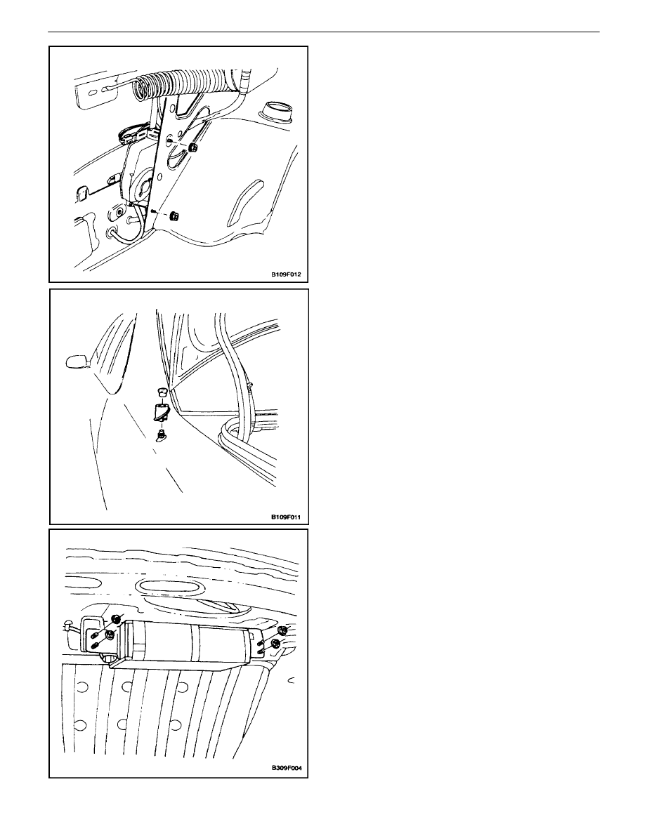
POWER ANTENNA MOTOR
(NOTCHBACK)
Removal Procedure
1. Disconnect the negative battery cable.
2. Remove the luggage compartment rear quarter trim
panel. Refer toSection 9G, Interior Trim.
3. Remove the antenna cap nut and the rubber grom-
met.
4. Loosen the nuts securing the antenna motor to the
vehicle.
5. Remove the antenna motor.
6. Disconnect the electrical connector and the drain
hose from the antenna motor.
AUDIO SYSTEMS 9F – 15
DAEWOO V–121 BL4
Installation Procedure
1. Connect the electrical connector and the drain hose
to the antenna motor.
2. Install the antenna motor with the nuts.
Tighten
Tighten the antenna motor nuts to 7 N
S
m (62 lb–in).
3. Install the antenna cap nut.
4. Install the luggage compartment rear quarter trim
panel. Refer to Section 9G, Interior Trim.
Tighten
Tighten the antenna cap nut to 7 N
S
m (62 lb–in).
5. Connect the negative battery cable.
COMPACT DISC CHANGER
Removal Procedure
1. Disconnect the negative battery cable.
2. Disconnect the CD changer electrical connector.
3. Remove the nuts and the CD changer.

9F – 16
I
AUDIO SYSTEMS
DAEWOO V–121 BL4
Installation Procedure
1. Install the CD changer with the nuts.
Tighten
Tighten the CD changer nuts to 7 N
S
m (62 lb–in).
2. Connect the CD changer electrical connector.
3. Connect the negative battery cable.

AUDIO SYSTEMS 9F – 17
DAEWOO V–121 BL4
GENERAL DESCRIPTION
AND SYSTEM OPERATION
AUDIO SYSTEMS
There are three audio systems available:
S
Stereo digital logic cassette AM/FM radio with elec-
tronic tape ejection.
S
Stereo digital logic AM/FM radio with CD player.
S
Trunk mounted CD changer which is available with
the cassette AM/FM radio.
AUDIO SECURITY SYSTEM
The audio security system is activated whenever the audio
system circuit is disconnected from the battery. A four–
digit security code must be entered in order for the audio
system to resume functioning. The security code is
stamped on a card located in the vehicle (usually in the
glove box). The following security code entering proce-
dure must be used to deactivate the audio security sys-
tem:
1. After connecting the audio security system to the
battery, ”COdE”will flash on the display.
2. Enter the proper security number into the unit, us-
ing the preset buttons No. 1 through 8. For exam-
ple, if the security number is ”1234”:
1) Press the preset button No. 1. ”COdE”: will dis-
appear and ”1–––” will appear on the display.
2) Press the preset button No. 2, and ”12––” will
appear.
3) Press the preset button No. 3, and ”123–” will
appear.
4) Press the preset button No. 4, and ”1234”will
appear.
1. The audio system will function and will transfer to
the radio.
If you fail to enter the correct security number into the unit,
”Err” will appear followed by ”COdE” and there will be sev-
eral audible beeps. If this happens, repeat the security en-
tering procedure beginning with step 2.
FRONT AND REAR SPEAKERS
All audio systems use four speakers: two speakers
mounted in the front doors and two speakers mounted in
the rear. A coaxial two–way rear speaker is offered as an
option.
TWEETER SPEAKERS
The tweeter speakers are mounted on the front door es-
chutcheon next to the dash panel.
MAST ANTENNA
The manual antenna is designed to withstand most car
washes without damage. If the mast becomes slightly
bent, it can be straightened by hand. The manual antenna
can be replaced if it is severely bent. Manual antennas
must be kept clean for good performance.
POWER ANTENNA
The optional power antenna is controlled by the radio.
When the radio power is turned on, the antenna is ex-
tended. When the radio is turned off, either by turning the
power off or by turning the ignition off, the antenna is re-
tracted.
ROOF ANTENNA
The two–piece roof antenna is standard equipment on the
hatchback and the wagon. The top half of the anten–na
can be unscrewed and removed if height clearance prob-
lems occur.
TAPE PLAYER AND CASSETTE
CARE
The head and the capstan are the two parts of the tape
player that should be cleaned. To clean the head and the
capstan, use a cotton swab dipped in rubbing alcohol. A
cassette cleaning kit may also be used to clean the head
and the capstan. Follow the cleaning kit instructions to
clean the tape player. This service should be performed
every 100 hours of cassette operation.
Do not touch the tape head with magnetized tools. If the
head becomes magnetized, it will degrade cassettes
played in the player. No service is performed on the cas-
settes. The cassette manufacturer handles warranties of
the cassettes. Store cassettes away from extreme heat
and direct sunlight.
COMPACT DISC CARE
Handle discs carefully. Store the discs in protective cases
away from the sun, heat, and dust. If the surface is soiled,
dampen a clean, soft cloth in a solution of mild neutral de-
tergent and wipe the disc clean.
Wyszukiwarka
Podobne podstrony:
Navigation and Audio System
diagnostics Audio System
Audio System for Built In Type Amplifier
Audio System for Separate Type Amplifier
16 E70 Audio Systems
93ZJ Secc 8F Audio Systems
09 E65 Audio System
04a E65 Audio System
07b E70 Audio Systems
07 E70 Audio Systems WB
96ZJ 8F AUDIO SYSTEMS
ANTILOCK BRAKING SYSTEM SECTION 4F 11
BODY WIRING SYSTEM SECTION 9A 11
NX650 Q Section 17 Ignition system
NX650 Q Section 17 Ignition system
więcej podobnych podstron