

Table of Contents
i
Foreword . . . . . . . . . . . . . . . . . . . . . . . . . . . . . . . . . . . . . . . . . . . . . . . . . . . . . . . . . . . iii
About the Author . . . . . . . . . . . . . . . . . . . . . . . . . . . . . . . . . . . . . . . . . . . . . . . . . . . . . iv
Unit 1. Introduction. . . . . . . . . . . . . . . . . . . . . . . . . . . . . . . . . . . . . . . . . . . . . . . . . . . . . . . . . . 1
Unit 2. NEC Introduction [Article 90] . . . . . . . . . . . . . . . . . . . . . . . . . . . . . . . . . . . . . . . . . . . . . 10
Unit 3. Definitions [Article 100] . . . . . . . . . . . . . . . . . . . . . . . . . . . . . . . . . . . . . . . . . . . . . . . . 12
Unit 4. General Installation Requirements . . . . . . . . . . . . . . . . . . . . . . . . . . . . . . . . . . . . . . . . . 14
Unit 5. Understanding Grounding Requirements . . . . . . . . . . . . . . . . . . . . . . . . . . . . . . . . . . . . . 17
Unit 6. Earth Grounding of Communications Systems . . . . . . . . . . . . . . . . . . . . . . . . . . . . . . . . . . 21
Unit 7. General Wiring Requirements . . . . . . . . . . . . . . . . . . . . . . . . . . . . . . . . . . . . . . . . . . . . 25
Table of Contents

ii
Guide to Low-Voltage & Limited Energy Systems

The National Electrical Code® (NFPA stan-
dard 70-1999) contains installation rules for all
kinds of electrical products and systems. It is
adopted into law by more than 42,000 states,
counties, cities, and smaller jurisdictions.
Many electrical professionals, including elec-
tricians, contractors, and even inspectors, think
of the Code primarily as a “power wiring” book.
And so it is. But not just power wiring. The
National Electrical Code also provides detailed
requirements for the installation of many types
of low-voltage wiring systems.
New businesses, home offices, and many
homes today are having low-voltage wiring
installed to meet the need for state-of-the-art
technologies for audio, video, telecorurnunica-
tions, and high speed data transfer. But many
electrical professionals are not familiar with the
important NEC® safety requirements for the
installation of non-power installations. Too often,
low-voltage systems aren’t installed properly or
inspected for Code compliance and user safety.
Some jurisdictions don’t even require electri-
cal permits for the installation of telephone,
cable TV, access control, nurse call, fiberoptic,
and other low-voltage control and communica-
tions circuits-even though these systems are cov-
ered by the National Electrical Code.
THE NEED TO INSPECT LOW-VOLTAGE
SYSTEMS
There are important safety reasons to inspect
low-voltage installations for Code compliance.
Here are just a few of them:
• Audio - Audio voltages can be as high as 70
volts AC.
• Telephone - Telephone ringing voltages can
be as high as 90 volts AC.
• Shock hazard - Incorrectly instalied low-
voltage wiring may accidentally become ener-
gized at line voltages, thus endangering both
installers and users.
• Grounding - Proper grounding of communi-
cation circuits, CATV cables, TV and satellite
masts, etc. are essential to prevent fires and elec-
tric shock from dangerous potential differences
between the electrical systems.
• Working space - In general, low-voltage dis-
tribution equipment must meet the same working
clearances as all other equipment rated under
600 volts [Section 110-16].
• Broadband - A new Article 830 on “Net-
work-Powered Broadband Communications Sys-
tems” was added to the 1999 Code, covering
futuristic Information Superhighway wiring sys-
tems for interactive multimedia services.
• Lifeline - Many jurisdictions now require
that free or low-cost “lifeline” telephone service
be made available to all citizens, recognizing that
telephone corurnunication is not an option but a
necessity in today’s world. With new types of
Internet and interactive services beginning to
take over the function of traditional telephones, it
is even more important that these alternative
low-voltage systems be installed safely and reli-
ably- in accordance with the National Electrical
Code.
Forword
iii
Foreword

iv
Guide to Low-Voltage & Limited Energy Systems
Mike Holt is a former electrician, contractor, and inspector. He is the author of many books and
videos books about the National Electrical Code, and is a regular contributor to Electrical Contractor
magazine. Holt lectures widely and conducts training classes nationwide on such topics as the NEC®,
exam preparation, electrical theory, and estimating and project management. For more information
about Mike’s publications and programs, contact:
Mike Holt Enterprises, Inc.
7310 McNab Road, Suite 201
Tamarac, FL 33321
1-888-NEC-CODE; (954) 720-7955 (fax)
www.mikeholt.com
email: mike@mikeholt.com
About the Author
Unit 1. Introduction
1
“Low-voltage and Limited-energy” are terms not
defined by the National Electrical Code. And
strictly speaking optical fiber cable systems,
which transmit information using high-speed
bursts of light generated by tiny lasers, are “no-
energy and no-voltage.” In developing this book
we considered various alternative terms for
describing all the different technologies. But in
the end, we decided to stick with “low-voltage
and limited-energy” to describe these diverse
systems because they are familiar terms widely
understood in the electrical industry.
Articles covering Low-voltage and limited-
energy devices, wiring, and systems are general-
ly contained in Chapter 7 and 8 of the National
Electrical Code. Even the Code itself seems m
consider them to be an after-thought, since it
groups most of them in the back of the NEC. In
addition to the requirements of Chapter 7 and 8,
we must be aware of the rules that apply to low-
voltage lighting (Article 411), Intrinsically Safe
Systems (Article 504), and Sound (Audio)
Systems (Article 640). The following is a brief
description of each system and its required
wiring method.
NEC CHAPTER 4- EQUIPMENT FOR
GENERAL USE
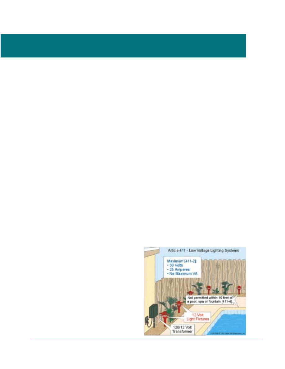
Article 411 - Low-Voltage Lighting
Article 411 covers listed low-voltage lighting
systems consisting of an isolating power supply.
Low-voltage show window and landscape light-
ing are examples of lighting systems required to
comply with Article 411. At the time of publica-
tion, there was no listed low-voltage lighting
system that complies with Article 411, but
Underwriters Laboratories Inc. (UL) is currently
developing a standard (UL 2108) for these sys-
tems, Fig. 1-1.
Power - Listed low-voltage lighting sys-
tems must operate at no more than 30
volts on the secondary, with each circuit
limited to 25 amperes [411-2].
Wiring Method - Low-voltage lighting
must be installed in accordance with the
listed system instructions [110-3(b)]
using listed systems power supply, fix-
tures, and cables [411-2].
NEC CHAPTER S - SPECIAL OCCUPANCIES
Article 504 - Intrinsically Safe Systems
Article 504 covers the installation of listed
intrinsically safe systems, apparatus, and wiring
in Class I, TI, and III hazardous (classified) loca-
tions. Intrinsically safe systems and devices such
as switches, thermocouples, light-emitting
diodes, connectors, and resistance temperature
devices limit spark or thermal temperatures to a
level that prevents ignition of flammable or
combustible material.
Unit 1. Introduction
FIGURE
1-1
Wiring Method – Intrinsically safe apparatus
and wiring can be installed exposed using any of
the wiring methods suitable for unclassified loca-
tions, including Chapter 7 and Chapter 8 cables
such as CL2 (Class 2), CL3 (Class 3), MP
(multi-purpose coaxial), or PLTC (power-limited
tray cable) [725-611.
NEC CHAPTER 6- SPECIAL EQUIPMENT
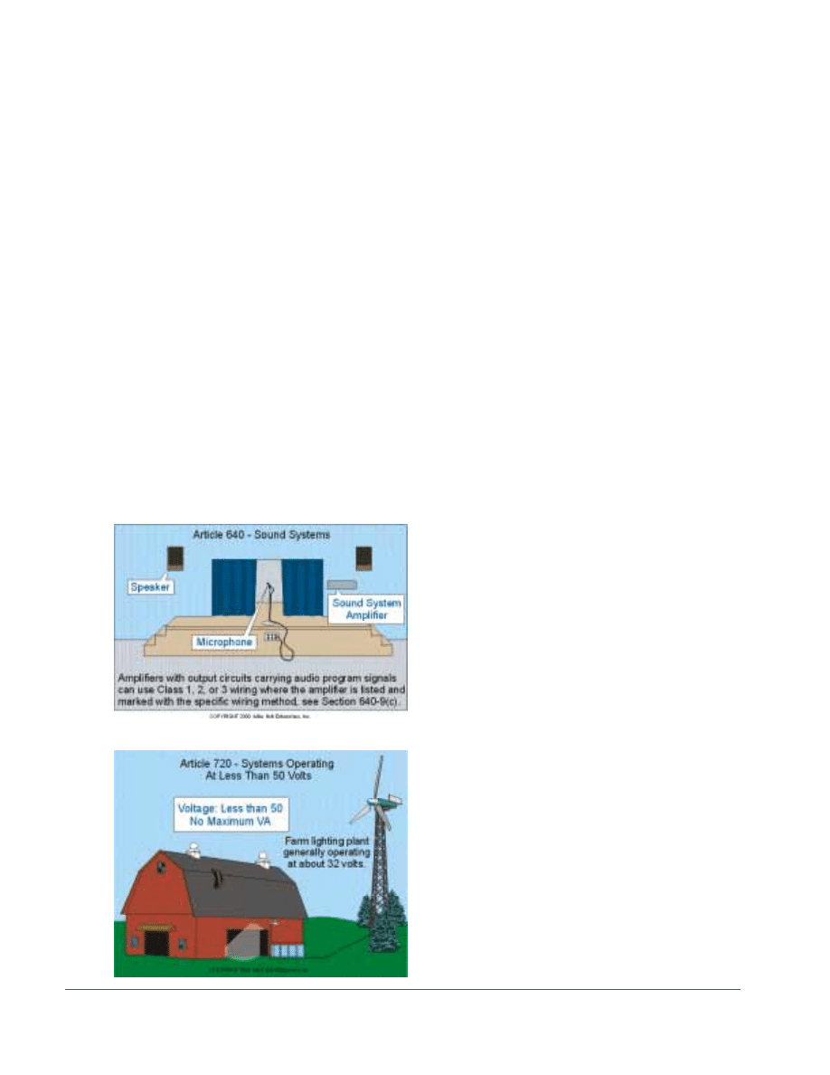
Article 640 - Sound Systems
Article 640 covers equipment and wiring for
audio signal generation, recording, processing,
amplification and reproduction; distribution of
sound, public address and speech-input systems;
temporary audio system installations; and elec-
tronic organs or other electronic musical instru-
ments.
Examples of permanently-installed distributed
audio system locations include but are not limit-
ed to restaurants, hotels, business offices, com-
mercial and retail sales environments, churches
and schools. Both portable and permanently
installed equipment locations include but are not
limited to residences, auditoriums, theaters, sta-
diums, movie and television studios. Temporary
installations include auditoriums, theaters, stadi-
ums, and outdoor events such as fairs, festivals,
circuses, public events and concerts, Fig. 1-2.
Note: Fire and burglary alarm signaling
devices are not covered by Article 640.
Power – Limited by the listing of the
product.
Wiring Method – The wiring method for
sound systems are dependent on the volt-
age and power output limitation of the
sound system equipment. It can be Class
1, Class 2 or Class 3 wiring according to
the amplifier listing and marking, but
generally the following applies [640-
• Class 2 Wiring Methods - Sound sys-
tems of 25 volts and not over 100 watts
(typically residential systems) must be
wired with Class 2 wiring methods.
• Class 3 Wiring Methods - Sound sys-
tems of 70.7 volts, and not over 100 watts
(typically commercial systems) must be
wired with Class 3 wiring methods.
• Class 1 Wiring Methods - All other
sound systems.
NEC CHAPTER 7-SPECIAL CONDITIONS
Article 720 - Circuits Operating At Less than 50
Volts
Article 720 was originally developed for low-
voltage installations known as “farm lighting
plants” which operate at about 32 volts (six 6-
volt batteries connected in series, allowing for
voltage drop), Fig. 1-3. Those in rural areas who
didn’t have access to electric utility power
installed this low-voltage system. Today, this
article applies to any low-voltage systems wiring
that is not covered by Articles 411-Low-voltage
Lighting, or 725-Control, Signaling and Power
Limited Circuits.
2
Guide to Low-Voltage & Limited Energy Systems
FIGURE
1-2
FIGURE
1-3
Power – Wiring complying with Article
720 cannot operate at more than 50 volts,
but there is no power or current limitation
for these systems.
Wiring Method – Section 90-3 specifies
that all wiring must be installed in accor-
dance with the general requirements of
Chapters 1 through 4 unless modified by
Chapters 5 through 7. Article 720 does not
modify the general requirements of Chap-
ter 1 through 4, therefore all wiring for
Article 720 installations must be in accor-
dance with Chapters 1 through 4, except
that the minimum conductor size is No.12
[720-4]. This means that 600 volt insulat-
ed conductors (minimum No.12) must be
installed in a Chapter 3 wiring method,
splices must be in outlet boxes [300-15],
and overcurrent protection must be as
specified in Section 240-3.
Article 725- Remote-Control, Signaling, And
Power-Limited Circuits
Article 725 contains requirements for remote-
control, signaling, and power-limited circuits that
are not an integral part of a device or appliance.
A remote-control circuit controls other circuits
through a relay or solid state device. A signaling
circuit supplies energy to an appliance or device
that gives a visual and/or audible signal. A
power-limited circuit is used for functions other
than signaling or remote-control. Article 725
classifies these types of circuits into Class 1, 2,
and 3 wiring systems.
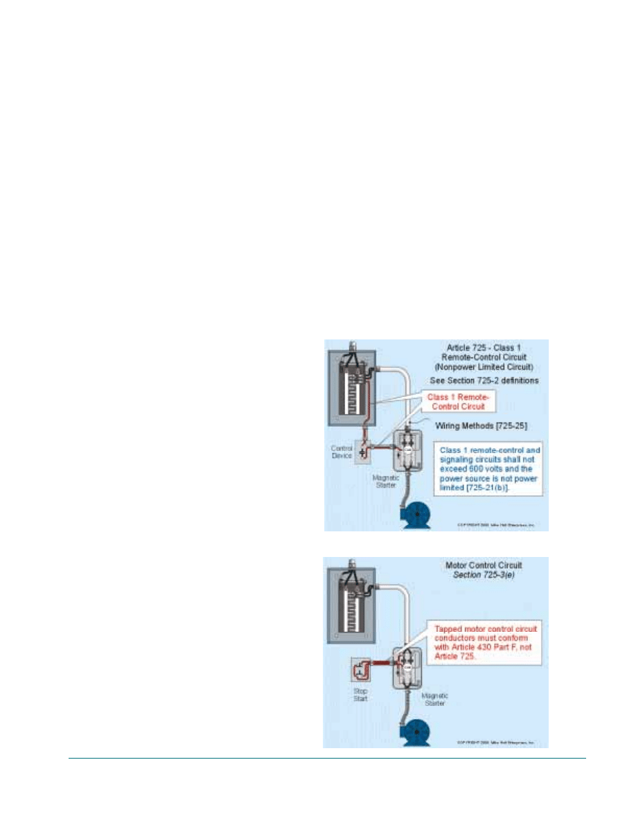
Class 7 Remote-Control and Signaling Circuit
[Article 725 - Part B]
A Class 1 remote-control and signaling circuit is
that portion of the wiring system between the
load side of the circuit overcurrent device and
the connected equipment. Class 1 circuits can
operate at up to 600 volts with no ampere limita-
tion [725-21(b)]. A motor control circuit with
individual overcurrent protection is considered a
Class 1 remote-control circuit and it must be
installed in accordance with Article 725, Part B,
Fig. 1-4.
Author’s Comment: Motor control
circuit conductors tapped to the
motor branch circuit supply conduc-
tors are not Class 1 conductors, but
rather motor control conductors as
defined in Section 430-71. Over-
current for these conductors must be
in accordance with the values listed
in Table 430-72(b), Fig. 1-5.
Power – Class 1 remote-control and sig-
naling cannot operate at more than 600
volts, and there is no power or current
limitation for these systems.
Wiring Method – All wiring for Class 1
remote-control and signaling circuits
must be in accordance with Chapters 1
through 4. This means that 600 volt insu-
lated conductors [725-27] must be
installed in a Chapter 3 wiring method
[725-25], splices must be in outlet boxes
[725-25], and overcurrent protection must
be as specified in Section 240-3 [725-24].
Unit 1. Introduction
3
FIGURE
1-4
FIGURE
1-5
Author’s Comment: Motor control
circuit conductors tapped from the
load side of a motor’s short-circuit
and ground-fault protective device
are not considered a Class 1 remote-
control circuit [725-3(e)]. The
motor control tap conductors must
be installed in accordance with the
requirements contained in Article
725 - Class 1 Power-Limited Circuit
Article 430, Part F, and not the
requirements in Article 725.
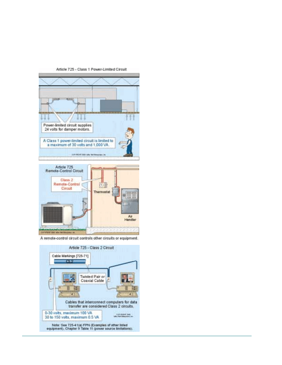
Power-Limited Class 1 Circuit [Article 725 Part B]
A power-limited Class 1 circuit is defined as that
portion of the wiring system between the load
side of the power-limited supply and the con-
nected equipment. Power-limited Class I circuits
are not as common as nonpower-limited Class 1
circuits. An example of their use would be to
operate low-voltage damper motors to control
environmental airflow, Fig. 1-6.
Power (1,000 VA) – Power-limited Class
1 circuits can be either ac or dc and must
be supplied from a power source that lim-
its the output to 30 volts and 1,000 VA
[725-21(a)]. Power-limited Class 1 cir-
cuits are necessary when the energy
demands of the system exceed the energy
limitations of Class 2 or Class 3 circuits
(100 VA) [Chapter 9 Table 11(a)].
Wiring Method – All wiring for power-
limited Class 1 circuits must be installed
in accordance with Chapters 1 through 4.
This means that 600 volt conductors
[725-271 must be installed in a Chapter 3
wiring method [725-251, splices must be
in outlet boxes in accordance with Sec-
tion 300-15 [725-25], and overcurrent
protection must be as specified in Article
240 [725-24].
Class 2 Circuit [Article 725 - Part C]
A Class 2 circuit is that portion of the wiring
system between the load side of a Class 2 power
source and the connected equipment. Class 2 cir-
cuits consider safety from a fire initiation stand-
point and provide protection from electric shock
by limiting the current [Chapter 9 Table 11(a)].
Class 2 circuits (not over 30 volts at 100 VA)
include wiring for thermostats, programmable
controllers, burglar and security systems, as well
as limited-energy voice, intercom, background
music, sound systems, and public address sys-
tems. In addition, cables (twisted-pair or coaxial)
that interconnect computers for Local Area Net-
works (LAN) are considered a Class 2 circuit,
see Section 725-41(a)(4), Fig. 1-7 and Fig. 1-8.
4
Guide to Low-Voltage & Limited Energy Systems
FIGURE
1-7
FIGURE
1-6
FIGURE
1-8
Note: A cable that connects the modem
of a computer to the telecommunications
system (telephone line) is considered a
telecommunications circuit and it must be
installed in accordance with the require-
ments of Article 800.
Power - Class 2 ac power sources must
be durably marked where plainly visible
to indicate the class of supply and electri-
cal rating. A Class 2 power source not
suitable for wet location use shall be so
marked.
Voltage Range
Power
Ampere
O to 2O Volts
100VA
5 ampere
2l to 3OVolts
100VA
3.3 ampere
31 to 150 Volts
0.5 VA
(5 milliamperes)
Wiring Method - Class 2 systems must
be wired with CL2, CM, or PLTC cables
[725-61] and a Chapter 3 wiring methods
cannot be used [725-52].
Class 3 Circuit [Article 725 - Part C]
A Class 3 circuit is that portion of the wiring
system between the load side of a Class 3 power
source and the connected equipment. Class 3 cir-
cuits consider safety from a fire initiation stand-
point. Because these circuits permit dangerous
voltages (up to 100 volts for inherently limited
power source) and power levels (100 VA)
[Chapter 9 Table 11(a)], the Code contains addi-
tional requirements to safeguard against electric
shock.
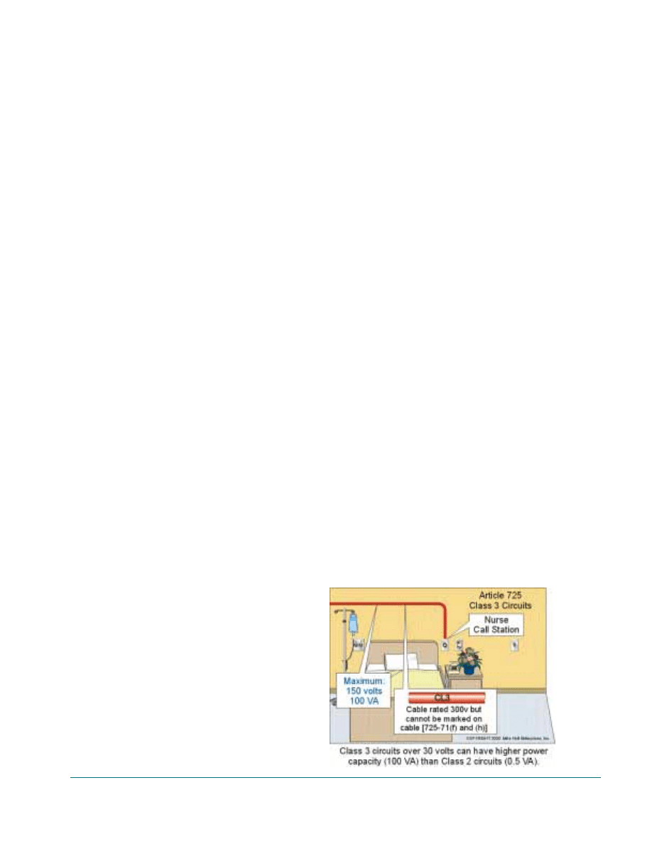
Class 3 circuits (over 30 volts not over 100
VA) are used for circuits operating at over 30
volts when the energy demands exceed 5 mil-
liamperes. Examples of Class 3 circuits would
include signaling circuits such as some burglar
and security systems; voice, intercom, back-
ground music, sound and public address systems;
as well as nurse call systems [640-2(b)].
Power - Class 3 ac power sources must
be durably marked where plainly visible
to indicate the class of supply and electri-
cal rating. Inherently-limited Class 3 ac
power sources power shall not exceed
100 VA when the voltage is between 31 to
100 volts and not inherently-limited Class
3 ac power sources must not exceed 100
VA when the voltage is between 31 to 150
volts, Fig. 1-9.
Wiring Methods - Class 3 circuit con-
ductors must be installed using either of
the following methods:
• Class 3 cable such as CL3, CM, or
PLTC listed for the application [725-61
and 725-71]. If the cables are installed in
a raceway, the raceway must be mechani-
cally installed in accordance with its nor-
mal rules. However, the raceway is not
required to be grounded, see Unit 5 of this
booklet.
• Single conductors not smaller than No.
18 (listed Type CL3) can be used and do
not have to be installed in a Chapter 3
wiring method. These conductors can be
installed as open single conductors
because they have passed the vertical
flame test and all the testing and listing
requirements of a CL3 cable.
Note: According to Section 725-71(g) in
the 1999 NEC, single conductor fixture
wire installed in a raceway or cable for
Class 3 circuits must be marked CL3.
Some believe this was not the intent of
the Code panel.
Unit 1. Introduction
5
FIGURE
1-9
CAUTION: Class 2 and Class 3 remote-
control circuits for safety-control equip-
ment shall be classified as Class 1 if the
failure of the equipment introduces a
direct fire or life hazard [725-8(a)]. An
example would be a boiler explosion
caused by the failure of the low-water
cutoff control circuit.
Article 727- Instrumentation Tray Cable
Instrumentation tray cable (ITC) is used in
industrial establishments where the conditions of
maintenance and supervision assure that only
qualified persons will service the installation.
ITC cable is a factory assembly of two or
more insulated conductors, with or without
grounding conductor(s), and enclosed in a non-
metallic sheath or armor. This system was added
to the 1996 National Electrical Code to make
legal a wiring method that had been used on off-
shore oil rigs for years.
Power (750 VA) - Type TTC cable cannot
be installed on any circuit that operates at
more than 150 volts or more than 5
amperes [727-1].
Wiring Method - Exposed TTC cable
must be listed and have a voltage rating of
not less than 300 volts [727-6]. In addi-
tion, because of the dangers associated
with Type ITC cables, splices must be
contained in outlet boxes or conduit bod-
ies in accordance with Section 300-15
[727-3], and overcurrent protection must
be as specified in Section 727-9.
Article 760 - Fire Alarm Signaling Systems
Article 760 covers the installation of wiring and
equipment for fire alarm systems, including all
circuits controlled and powered by the fire alarm
system. Fire alarm systems include fire detection
and alarm notification, voice communications,
guard’s tour, sprinkler waterflow, and sprinkler
supervisory systems. Circuits controlled and
powered by the fire alarm system include eleva-
tor capture, elevator shutdown, door release,
smoke doors and damper control, fire doors and
damper control, and fan shutdown, but only
where these circuits are powered by and con-
trolled by the fire alarm system [760-1]. There
are two types of fire alarm systems, nonpower-
limited and power-limited.
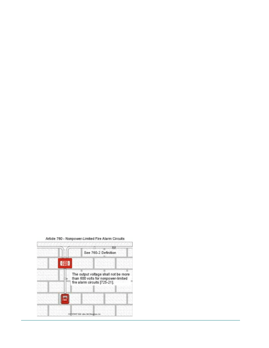
Nonpower-Limited Fire Alarm (NPLFA) Circuits
[Article 760 - Part B]
A nonpower-limited fire alarm circuit is that
portion of the wiring system between the load
side of the overcurrent protection device and the
connected equipment of all circuits powered and
controlled by the fire alarm system.
Power - Nonpower-limited fire alarm cir-
cuits cannot operate at more than 600
volts, and there is no power or current
limitation for these systems, Fig. 1-10.
Wiring Methods - Nonpower-limited
fire alarm circuits (not exceeding 150
volts) conductors must be installed using
either of the following methods:
• An acceptable wiring method described
in Chapter 3. Splices must be in outlet
boxes in accordance with Section 300-15
[760-25], and overcurrent protection must
be as specified in Article 240 [760-23].
• Exposed listed nonpower-limited fire
alarm cable marked Type NPLFA (non-
power-limited fire alarm) cable can be
used where not subject to physical dam-
age [760-30].
Power-Limited Fire Alarm (PLFA) Circuits [Article
760- Part C]
A power-limited fire alarm circuit is that por-
tion of the wiring system between the load side
of a power-limited fire alarm transformer, Class
3 transformer or fire alarm control panel [760-
6
Guide to Low-Voltage & Limited Energy Systems
FIGURE
1-10
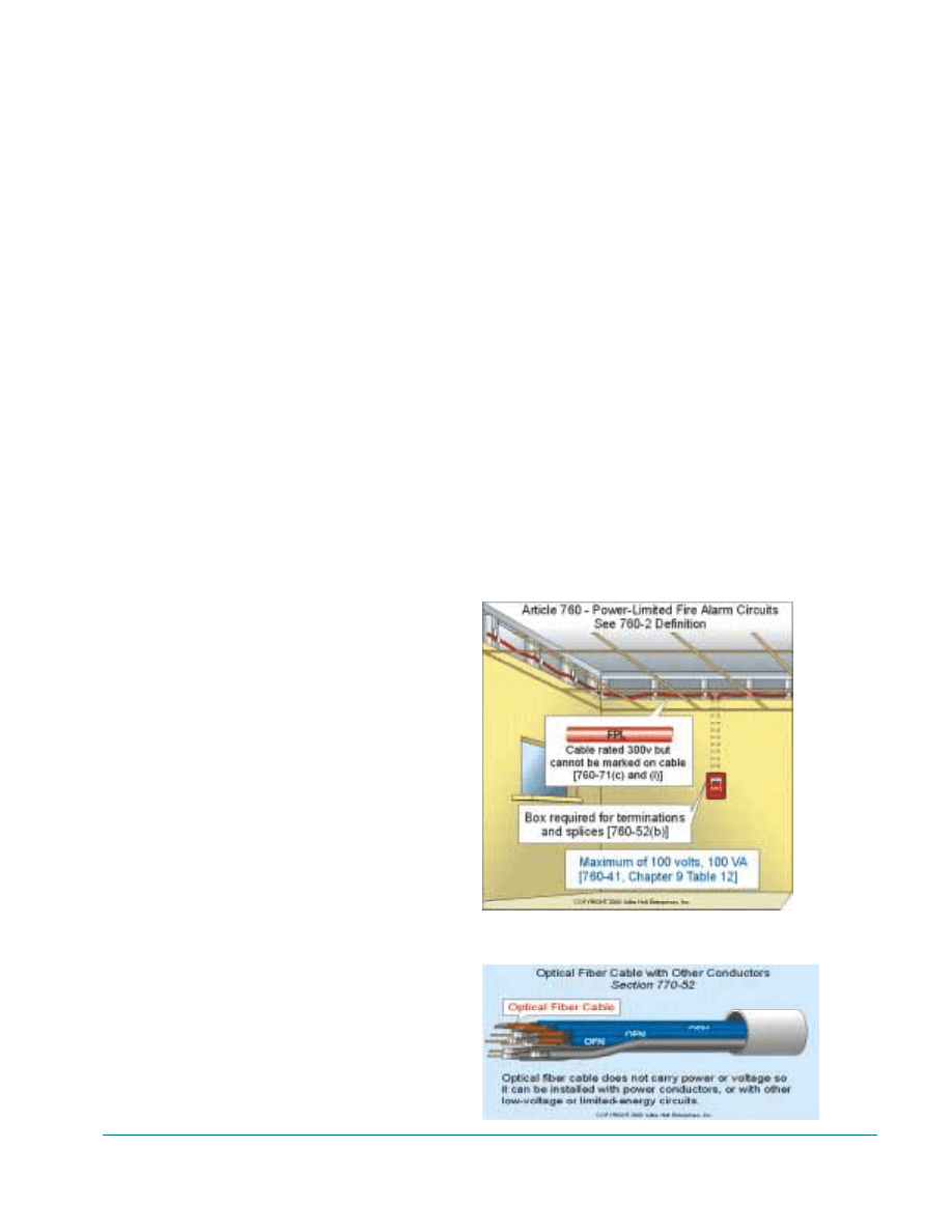
41] and the connected equipment of all circuits
powered and controlled by the fire alarm system,
Fig. 1-11.
Power-Limited Fire Alarm Circuit
Power (Inherently-Limited) (ac)
Voltage
Power
Ampere
O to 20 Volts
100VA
5 ampere
2O to 3O Volts
100VA
3.33 ampere
3O to 100 Volts
100 VA
1 ampere
Wiring Methods - Power-limited fire
alarm circuit conductors must be installed
using either of the following methods:
• An acceptable wiring method described
in Chapter 3, splices must be in outlet
boxes in accordance with Section 300-15
[760-52(a)],
• Exposed Power-Limited Fire Alarm
(FPL) cables, communications wires and
cables (CM), and multipurpose coaxial
cables (MP) [Figure 760-61] can be used
where not subject to physical damage
[760-52(b) and 760-61]. But all splices
and devices must be installed within an
outlet box in accordance with Section
300-15 [760-52(b)].
Article 770- Optical Fiber Cables and Raceways
Article 770 covers optical fiber cables used to
transmit light for control, signaling, and commu-
nications. This article also contains the require-
ments for composite cables (often called
“hybrid” in the field) that combine optical fibers
with current-carrying metallic conductors.
Wiring Method - Optical fiber cable
does not carry power or voltage, therefore
the cable can be installed with power con-
ductors, or with other low-voltage or lim-
ited-energy circuits [770-52], Fig. 1-12.
Optical fiber cables must be marked
“OFC.” Optical fiber cables are not
required to be installed within a raceway,
but if installed in a raceway, it must be a
listed optic-fiber raceway or of a type
described in Chapter 3 of the Code [770-
6].
Article 780- Closed-Loop Power Distribution
Article 780 covers the “Smart House” wiring
system, which uses a special flat cable combin-
ing No.12 power conductors with Class 2 and 3
twisted-pair and coaxial conductors.
Author’s Comment:
Effective
August 1997, Smart House, L.P
declared bankruptcy. Type NMS
cable described in Article 780 is no
longer manufactured but is still
available.
NEC CHAPTER 8- COMMUNICATIONS
SYSTEMS
Chapter 8 of the National Electrical Code covers
the wiring requirements for communications sys-
tems such as wiring for telephones, radio and TV
antennas, satellite dishes, CCTV and CATV
Unit 1. Introduction
7
FIGURE
1-11
FIGURE
1-12
systems. The installation requirements for com-
munications Systems contained in Chapter 8 are
independent of the Code requirements for Chap-
ters 1 through 7, except where they are specifi-
cally referenced [90-3].
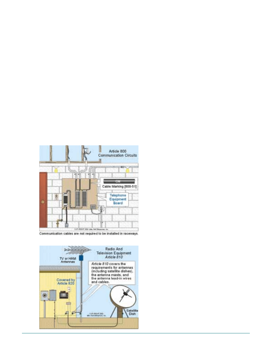
Article 800 - Telecommunications (Telephone)
Circuits
Article 800 covers the installation requirements
for telephones and wiring for other related
telecommunications purposes such as computer
local area networks (LAN) and fire and burglar
alarm systems connected to central stations, Fig.
1-13.
Wiring Methods - The NEC requires
telecommunications cables to have a volt-
age rating of not less than 300 volts
[800-50 and 800-511. Cables that meet
this requirement are marked CM (Com-
munications) or MP (Multipurpose).
Optical fiber cables used for telecommu-
nications circuits must be installed in
compliance with the requirements of Arti-
cle 770 [800-52(a)(1)].
Author’s Comment: Cables used
for computers for the purpose of
exchanging data must be installed in
compliance with Article 725, Class
2 signaling circuits, not Article 800
[725-41(a)(4)].
Article 810 - Radio and Television Equipment
Article 810 covers antenna systems for radio and
television receiving equipment, amateur radio
transmitting and receiving equipment, and cer-
tain features of transmitter safety. This Article
covers antennas such as multi-element, vertical
rod, dish, as well as wiring and cabling that con-
nects them to the receiving equipment, Fig. 1-14.
Wiring Methods - Exposed cables
wiring for connecting antennas to equip-
ment must be Type CATV or CM [Figure
820-531 installed in accordance with
Article 820 [810-2] or Type OF optical
fiber cable installed in accordance with
Article 770 [8l0-2]. Wiring for sound sys-
tems such as “surround sound” must be
installed in accordance with Article 640 -
Sound (Audio) Systems.
IMPORTANT NOTE: Neither Article
810 nor any other Article deals with
power-line carrier (PLC) automation con-
trol systems, such as X-10 or CEBus.
These systems transmit an electrical sig-
nal over the existing building power con-
ductors to control receiving devices for
home automation, security, and factory
automation processes. Section 810-1 of
the National Electrical Code specifies
that equipment and antennas used for
coupling carrier current to power line
conductors are not within the scope of
Article 810.
8
Guide to Low-Voltage & Limited Energy Systems
FIGURE
1-14
FIGURE
1-13
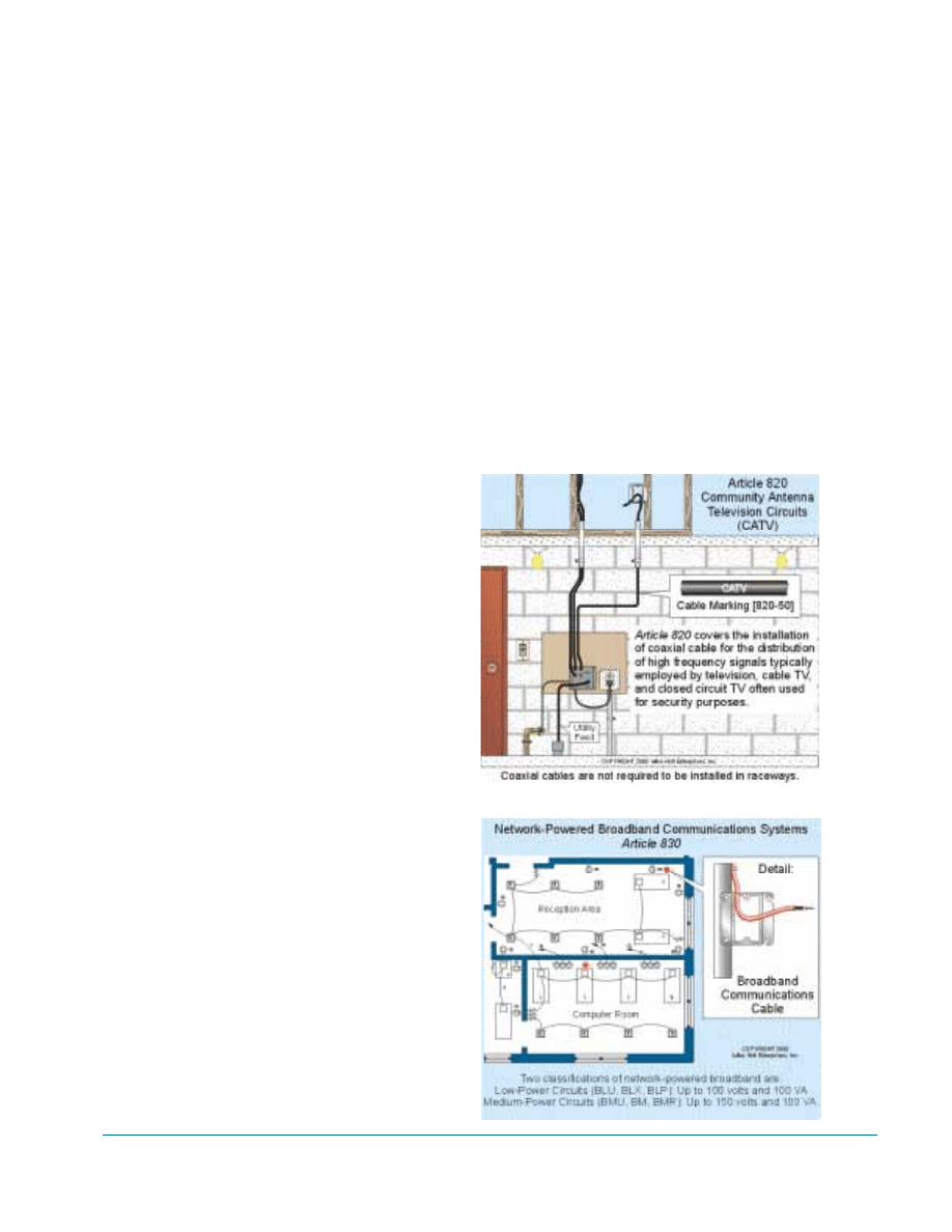
Article 820- Community Antenna Television
Systems
Article 820 covers the installation of coaxial
cables for the distribution of limited-energy high
frequency signals for television, cable TV, and
closed circuit television (CCTV) often used for
security purposes [810-2], Fig. 1-15.
Wiring Methods – Exposed coaxial
cables must be Type CATV or CM
installed in accordance with Article 820
[820-53].
Author’s Comment: Coaxial cable
used to interconnect computers for
the purpose of exchanging data for
Local area networks (LAN) or
corporate office intranets must be
installed in accordance with Article
725, Class 2 or 3 circuits [725-
41(a)(4)].
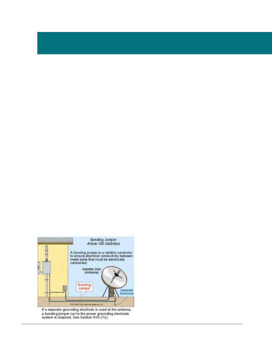
Article 830- Network-Powered Broadband
Communications Systems
This new Article is intended to provide the
necessary requirements for network-powered
broadband communications systems that provide
voice, audio, video, data and interactive services
through a network interface unit (NIU).
An example of a network-powered broadband
communications system would be hybrid fiber-
coaxial (HFC) cable used for video/audio con-
ferencing or interactive multimedia entertain-
ment systems, Fig. 1-16.
Two classifications of network-powered
broadband communications system circuits have
been accepted for the 1999 Code and both types
involve some risk of electric shock. The intent of
Article 830 is that the classification limits,
together with wiring methods and mechanical
protection, should result in an installation
equivalent in safety to those now permitted in the
NEC.
Low-Power Circuits
Low-power circuits are essentially the same as
“Not Inherently Limited Class 3 circuits up to
100 volts and 100 VA.” These circuits are intend-
ed to power one network interface unit (NIU)
installed in a single family residence.
Wiring Methods – Prior to January 1,
2000, existing coaxial cable types can be
used for low-power broadband systems.
After that date only listed Type BL
(Broadband Low-power), BM (Broad-
band Medium-power), CM, or MP coaxi-
al cables can be used.
Medium-Power Circuits
Medium-power circuits are similar to “Class 3
circuits up to 150 Volts and 100 VA.” These cir-
cuits are intended to provide power for multiple
NIUs or a single NIU with expanded capabili-
ties. The circuit voltage of 150 volts permits
greater distances between supply locations (or
longer transmission lines).
Wiring Methods – Only listed BM, CM,
MP coaxial cables can be used.
Unit 1. Introduction
9
FIGURE
1-15
FIGURE
1-16

10
Guide to Low-Voltage & Limited Energy Systems
CODE ARRANGEMENT [90-3]
General Requirements – The general require-
ments of Chapters 1 through 4 apply to all instal-
lations, except for communications wiring cov-
ered in Chapter 8.
Author’s Comment: Only those
Sections of Article 300 referenced
in Sections 725-3, 760-3, and 770-3
apply to low-voltage or limited-
energy wiring.
Special Requirements - The general require-
ments of Chapters 1 through 4 apply to all
Chapters 5 through 7 wiring system, unless a
specific rule in Chapter 7 modifies the general
requirements or adds additional requirements.
Sections 725-3, 760-3, and 770-3 modify the
general rule and specify that only those Sections
in Articles 300 referenced in Articles 725-, 760,
and 770 apply to low-voltage or limited-energy
wiring.
Example. Article 720 does not modify the
general requirements, therefore all of the require-
ments of Chapter 3 apply systems and equipment
operating at less than 50 volts.
Communications Systems – Chapter 8 contains
the requirements for communications circuits
such as telephone, satellite dishes, TV antennas,
CATV, and network-powered broadband com-
munications systems. The requirements of Chap-
ter 8 are independent of Chapter 1 through 7
requirements, unless a Code Section in Chapter 8
makes a specific reference to those general
requirements.
Tables – Chapter 9 contains tables that apply
to limited-energy systems, such as Table 11 for
Class 2 and 3 power limitations, and Table 12 for
Fire Alarm power limitations.
ENFORCEMENT OF THE NATIONAL
ELECTRICAL CODE [90-4]
The Code specifies the inspector’s responsibil-
ities; these include interpretation of the Code
rules, determining approval of equipment, grant-
ing special permission, waiver of rules for new
material requirements, and ensuring that equip-
ment is installed properly.
Interpretation of NEC rules – Electrical
inspectors have the responsibility to interpret the
Code, but the inspector must have a Code rule to
base the interpretation on. Electrical inspectors
do not have the authority to require an electrical
installation to exceed NEC requirements.
Approval of equipment and materials – The
Code requires some equipment to be listed for its
use, but it does not require all equipment to be
listed. The electrical inspector determines the
suitability of equipment and approves its use.
The basis of equipment approval is often the list-
ing by National Recognized Testing Laboratories
(NRTL) [90-7 and 110-2]. However, the NEC
requires low-voltage and limited-energy cables
installed indoors to be listed [725-71, 770-50,
800-49, 820-49, 830-54 and 830-55]. As a result,
there are currently no low-voltage or limited-
energy cables listed for installations under-
ground, outdoors, or in wet locations. Inspectors
permit (approve) nonlisted cables to be installed
underground, outdoors, or in wet locations where
the manufacturer has identified them as suitable
for this purpose, Fig. 2-1.
Unit 2. NEC Introduction
[Article 90]

Granting of special permission – Section 90-4
gives the electrical inspector authority to permit
alternate methods when an installation is not
covered by the Code, or where noncompliance is
necessary. But this is only permitted where
equivalent electrical safety can be achieved.
There will be occasions when the electrical
inspector will need to grant special permission,
simply so the low-voltage or limited-energy sys-
tem can perform its intended function or pur-
pose.
Ensure that equipment is installed properly –
It is the inspector’s responsibility to ensure that
electrical equipment is installed and used in
accordance with the equipment’s listing or label-
ing instructions [1 10-3(b)]. In addition, the
inspector is responsible for detecting field modi-
fication of listed equipment that could compro-
mise the equipment’s listing [90-71.
PRODUCT EVALUATION FOR SAFETY
[90-7]
Evaluation of products for safety is performed
by Nationally Recognized Testing Laboratories
(NRTL) that publish a list of equipment that
meets nationally recognized test standards.
Product listing decreases the need for inspectors
to re-inspect or evaluate the electrical equipment
at the time of installation. Listing and labeling
by NRTL is the primary basis for equipment
approval by electrical inspectors [90-4 and 1l0-
2J.
Unit 2. NEC Introduction [Article 90]
11
FIGURE
2-1
12
Guide to Low-Voltage & Limited Energy Systems
Article 100 contains definitions of terms often
used throughout the Code. The official dictionary
of the NFPA is the IEEE Standard Dictionary of
Electrical and Electronic Terms (ANSI/IEEE
100-1997). In addition, definitions are also locat-
ed throughout the Code in some of the articles.
Some important definitions for the application of
low-voltage and limited-energy systems are as
follow.
Note: Definitions below marked with (*)
are not contained in the National
Electrical Code.
Approved: “Approved” means acceptable to
the authority having jurisdiction, which is usual-
ly the electrical inspector. Many think that if the
equipment is listed or labeled, then it is
approved. This is not the case [90-4, 90-7 and
110-21, see Fig. 2-1.
Example: Section 110-12(a) specifies
that unused openings in electrical equip-
ment must be closed with an approved
(not a listed) fitting that provides protec-
tion equivalent to the wall of the equip-
ment.
Bonding/Bonded: Bonding means to electri-
cally join or tie together. Bonding is important
for the purpose of ensuring that metal parts are
properly grounded by a Tow-impedance path.
Example: Section 810-21(d) requires
satellite entrance cable to be earth
grounded by a No. 10 or larger copper
conductor run to the building or structure
grounding electrode system. If the
grounding conductor is run in a metal
raceway, then both ends of the metal race-
way must be effectively bonded to the
grounding conductor.
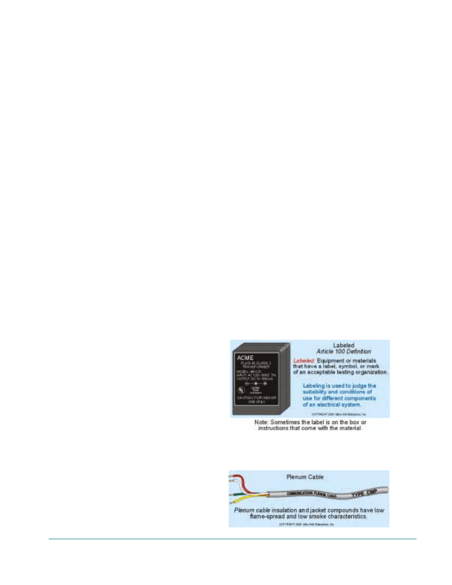
Bonding Jumper: A reliable conductor to
ensure electrical conductivity between metal
parts that must be electrically connected. The
NEC does not have any requirement for the color
of the bonding jumper, but traditionally electri-
cians use a green insulated wire, or a black wire
marked with green tape. Telephone and CATV
companies generally use a gray insulated con-
ductor.
Example: Section 810-21(d) states that a
bonding jumper, not smaller than No.6
copper, must be connected between a
radio, television, or HAM equipment
grounding electrode and the power
grounding electrode system, where sepa-
rate electrodes are used, Fig. 3-1.
*Broadband: Transmission facilities capable
of handling a wide range of frequencies simulta-
neously, permitting multiple channels. Coaxial
and optical fiber cables are inherently broad-
band.
Unit 3. NEC Definitions
[Article 100]
FIGURE
3-1
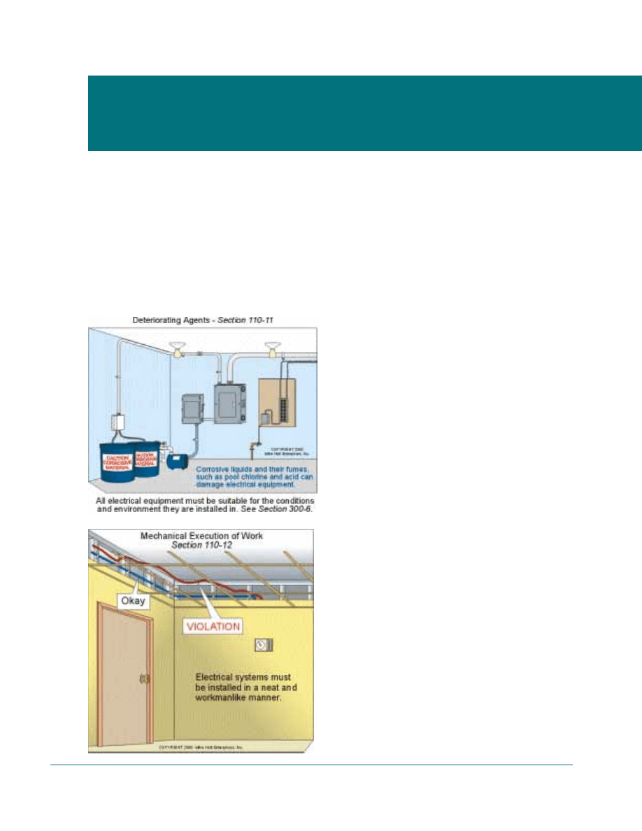
Labeled: Equipment or materials with a label,
symbol, or other identifying mark, applied by a
Nationally Recognized Testing Laboratory
(NRTL) acceptable to the inspector. Labeled and
listed equipment provides the basis for inspector
approval of the equipment. Many are familiar
with the testing laboratory labels on electrical
equipment, which may be in the form of a stick-
er, decal, printed label, or molded into the prod-
uct itself [90-4, 90-7, 110-2, and 110-3], Fig. 3-
2.
Author’s Comment: According to
Section 110-3(b) listed or labeled
equipment must be installed, used,
or both, in accordance with any
instructions included in the listing
or labeling.
Listed: “Listed” means that the equipment or
material is on lists published by Nationally Rec-
ognized Testing Laboratories that maintain peri-
odic inspection of production of listed equipment
or material. The material listing indicates that
appropriate designated standards have been met,
or the material has been tested and found suit-
able for use in a specified manner. The Code
does not require all electrical equipment to be
listed, but some rules do specifically require list-
ed material/equipment.
Author’s Comment: Sections 725-
71, 760-31, 770-50, 800-50, and
820-50 specify that low-voltage and
limited-energy cables installed
within buildings must be listed.
However, UL Standard 444 does not
test low-voltage or limited-energy
cables for direct burial, exposure to
ultraviolet rays of the sun, or stand-
ing water because these cables are
intended to be installed indoors.
NEC requirements drive the UL
standards, and currently there is no
NEC requirement to list these types
of low-voltage and limited-energy
cables for outdoor use.
Cable manufacturers produce “gel-filled”
cables that they consider suitable for
installation underground or in wet loca-
tions. There’s no uniform marking on the
cable jacket to indicate this purpose; for
instance West Penn Wire marks its cables
“AQC”, which stands for their registered
trade mark - Aqua Seal, whereas other
manufacturers use different markings.
Author’s Comment: The suitabili-
ty of communications cables
installed in wet locations or exposed
to the direct rays of the sun is gen-
erally not a safety Code issue. But it
could be for fire protection or secu-
rity systems wiring installed out-
doors. As users become more
informed on the needs of low-volt-
age and limited-energy systems, it is
likely that the Code will be changed
to require that all cable types be list-
ed and labeled for their intended
application or purpose.
*Plenum Cable: A cable that’s listed for
exposed installation in plenums without the need
for conduit because the insulation and jacket
compounds have low flame-spread and low
smoke characteristics. This type of cable is
required when installed in a space used to move
environmental air, such as the space above a sus-
pended ceiling for return air, Fig. 3-3.
Unit 3. Definitions [Article 100]
13
FIGURE
3-2
FIGURE
3-3
14
Guide to Low-Voltage & Limited Energy Systems
Note: None of the requirements in Article
110 apply to communications circuits
(NEC Chapter 8), but some apply to
Chapters 6 and 7 wiring systems 190-31.
Approval of Equipment [110-21
The authority having jurisdiction must
approve all electrical equipment 190-41 and this
includes low-voltage and limited-energy equip-
ment and cables (see Article 100 for the defini-
tion of approved) [see Fig. No.1 in Unit 2].
Equipment Listing Instructions [110-3(b)]
All electrical equipment must be installed,
and/or used according to its listing and labeling
instructions. Equipment that is not listed or
labeled can still be used, but the electrical
inspector must approve its use.
Author’s Comment: Section 800-4
requires equipment intended to be
electrically connected to a telecom-
munications network to be listed for
the purpose, and the equipment
installations must comply with Sec-
tion 110-3(b).
Deteriorating Agents [110-11]
Low-voltage and limited-energy equipment must
be suitable for the environment such as moisture,
solar exposure, gases, fumes, vapors, excessive
temperatures, or any other agent that could have
a detrimental effect on the equipment or conduc-
tors. In addition, electrical equipment approved
for use in dry locations must be protected from
the weather during the building construction
period, Fig. 4-1.
Mechanical Execution of Work [110-12]
Electrical systems including low-voltage and
limited-energy systems must be installed in a neat
and workmanlike manner. This rule is also con-
tained in the following Code Sections, Fig. 4-2:
Unit 4. General Installation
Requirements
FIGURE
4-1
FIGURE
4-1
System
Section
• CATV, MATV, and CCTV
820-6
• Circuits Less Than 50 volts
720-12
• Class 1, Class 2, and Class 3
725-7
• Fire Alarm
760-8
• Optical Fiber Cables and Raceways
770-8
• Network Broadband
830-7
• Telecommunications
800-6
Note: MAIW - Master Antenna Television
Systems,
CCTV - Closed Circuit
Television System
Author’s Comment: The National
Electrical Contractors Association
(NECA), in conjunction with other
organizations is currently develop-
ing National Electrical Installation
Standards™ to define the intent of
the Code rules.
Protection of Internal Parts [110-12(c)]
Special care must be taken to protect the internal
parts of electrical equipment to guard against
damage or contamination by foreign material
such as paint, plaster, cleaners, etc.
Conductor Terminations [110-14(a)]
Connection of conductors to terminals shall
ensure a mechanically and electrically sound
connection without damaging the conductors.
Terminations shall be made by means of pressure
connectors (including set-screw type), solder
lugs, or splices to flexible leads. Terminals
intended for more than one conductor and termi-
nals used to connect aluminum must be listed
and identified for the purpose.
Conductor Splices [110-14(b)]
Low-voltage cables and conductors must be
spliced using listed connectors. The standard
practice of twisting the wires together and cov-
ering them with electrical tape does not meet the
requirement of this Section.
Author’s Comment: A box or con-
duit body is not required at each
conductor splice, connection point,
junction point, or pull point for low-
voltage and limited-energy circuits.
Manufacturer’s Markings [110-21]
Electrical equipment must be marked with the
manufacturer’s identification. Additional mark-
ings required by other Code sections could
include voltage, current, wattage, or other ratings
and these markings must withstand the intended
environment involved.
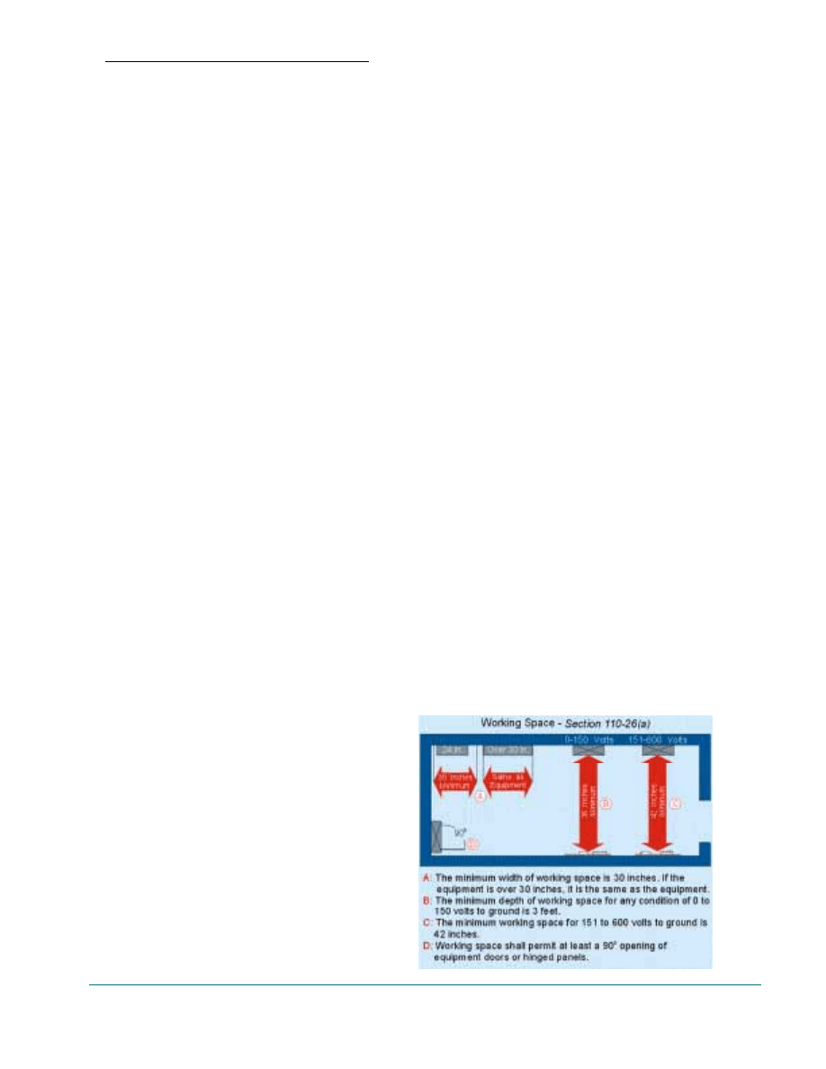
Working Space [110-26]
For the purpose of safe equipment operation and
maintenance, all electrical equipment must have
sufficient access and working space, Fig. 4-3.
Question: Does low-voltage and limited-ener-
gy systems require the same working space as
power conductors and equipment?
Answer: Section 110-26 requires working
space for all systems. However, the generally
accepted practice is not to require working space
for low-voltage and limited-energy systems, but
to install these systems so as not to encroach on
the working space requirements of the power
equipment.
Width. The working space in front of equip-
ment must be a minimum of 30 inches wide, but
in no case less than the width of the equipment.
Depth. Equipment must be installed so that
the working space from the low-voltage and lim-
ited-energy equipment to nearby higher voltage
equipment is not less than 3 feet (measured from
the enclosure front) for 120/240 volt or
Unit 4. General Installlation Requirements
15
FIGURE
4-3
208Y1120 volt systems. For 480Y1277 volt sys-
tems, the working space must not be less than 3
feet from low-voltage or limited-energy equip-
ment. In all cases, the working space must be of
sufficient width, depth, and height to permit a
900 opening of all equipment doors.
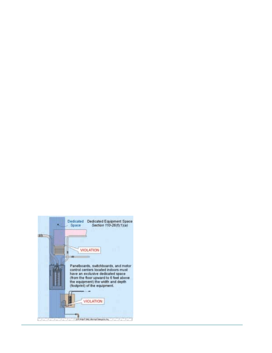
Dedicated Space [110-26(1)]
The “dedicated equipment space” for electrical
equipment was revised to require dedicated space
the width and depth (footprint) of the equipment
from the floor to a height of 6 feet (was 25 feet)
above the equipment, or to the structural ceiling,
whichever is lower. No piping, ducts, or equip-
ment foreign to the electrical installation shall be
located in this zone, Fig. 4-4.
Author’s Comment: Low-voltage
and limited-energy equipment can-
not be installed within the dedicated
space above and below panelboards
or switchboards [11 0-26(f)].
Protection Against Physical Damage
[170-27(b)]
Electrical equipment must not be installed
where it can be exposed to physical damage.
Enclosures or guards must be used to protect
electrical equipment that could be exposed to
physical damage. Exposure to physical damage
is subject to interpretation by the electrical
inspector.
Sound Systems [640-4]
Sound system equipment such as amplifiers,
rectifiers, and loudspeakers must be located or
protected to guard against physical damage,
which might result in fire or personal hazard.
Safety-Control Equipment [725-8]
Where damage to remote-control circuits
introduces a direct fire or life hazard, all conduc-
tors shall be installed in rigid metal conduit,
intermediate metal conduit, rigid nonmetallic
conduit, electrical metallic tubing, Type MC
cable, or be suitably protected from physical
damage.
Fire Alarm Power-Limited Circuits [760-52(b)]
Power-limited fire alarm circuit conductors
and cables shall be installed in such a way that
maximum protection against physical damage is
afforded.
16
Guide to Low-Voltage & Limited Energy Systems
FIGURE
4-4
Unit 5. Understanding Grounding Requirements
17
The purpose of the National Electrical Code
is for the practical safeguarding of persons and
property from hazards arising from the use of
electricity [90-1(a)]. The proper application and
installation of equipment grounding will signifi-
cantly reduce the hazards that exist in the use of
electricity.
Article 250 of the NEC covers the general
rules and specific requirements of when systems
are required to be grounded, the locations of
grounding connections, the size and types of
grounding conductors, bonding conductors, and
electrodes, and the methods of grounding and
bonding. To better apply the NEC’s grounding
rules, you must understand that there are two dif-
ferent methods of grounding and that they serve
different purposes: “Safety Grounding” and
“Earth Grounding.”
Safety Grounding (Equipment Grounding)
[250-2(b)]
The purpose of grounding electrical metal
enclosures is to remove dangerous voltage
(potential) to protect against electric shock
and/or electrocution of persons in contact with
energized metal parts, due to a ground-fault. In
addition, the fault must be removed quickly
before a fire develops.
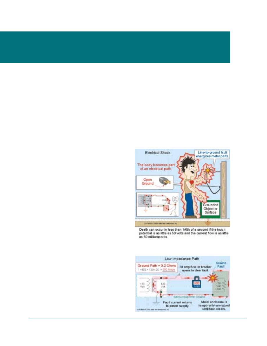
Electric Shock. People die when voltage push-
es electrons through their bodies, particularly
through the heart. If a person makes contact
between an object that has voltage and another
object that is grounded, current will flow through
those contact points. Humans are susceptible to
death when exposed to currents as low as 20 mA
(20/1,000 ampere) for a fraction of a second,
Fig. 5-1.
To remove the dangerous voltage, the circuit
overcurrent protection device must open quickly
to clear the ground-fault. To open the overcurrent
protection device, the grounding path must have
an impedance that is low enough to permit
ground-fault current to reach a level of at least
five times (preferably 10 times) the overcurrent
protection device’s rating. This can be accom-
plished by bonding metal parts to each other and
then bonding the metal parts to the system
Unit 5. Understanding Grounding
Requirements
FIGURE
5-1
FIGURE
5-2
grounded conductor (neutral) resulting in a low
ground-fault return path, Fig. 5-2.
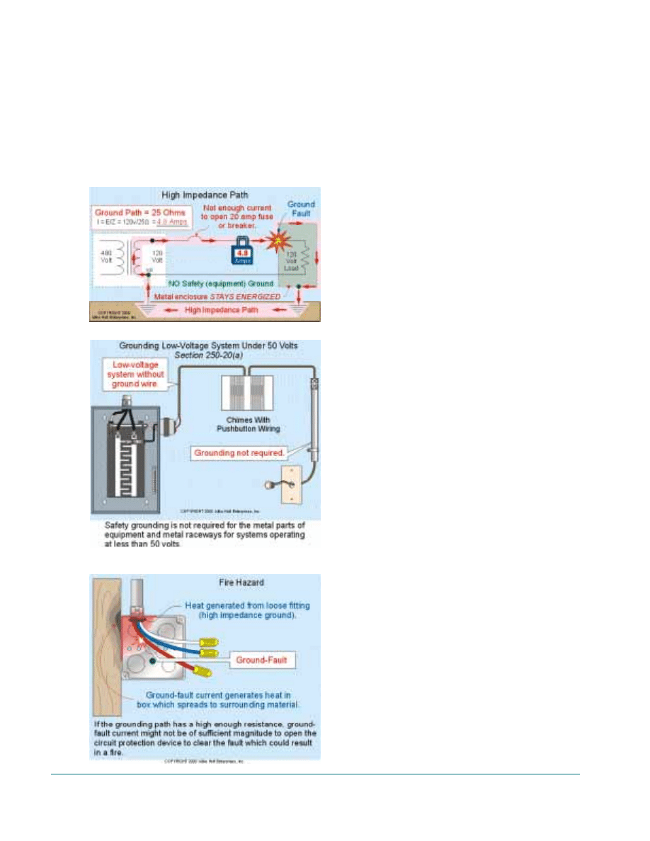
Danger: The earth is a high impedance path
for ground-fault current and cannot be used for
equipment grounding [250-2(d) and 250-541.
The high impedance of the earth results in very
low current flow during ground-fault conditions
and the ground-fault not clearing. If a grounding
electrode (earth) were used as the equipment
grounding conductor, the maximum current that
could flow would be a function of the ground-
fault voltage divided by the earth’s impedance,
or I = E/Z, Fig. 5-3.
Safety grounding is not required for the metal
parts of equipment and electrical raceways for
low-voltage systems that operate at less than 50
volts [250-20(a)1, Fig. 5-4. However, metal race-
ways for low-voltage and limited-energy circuits
that may become energized by higher voltage
systems must be bonded in accordance with Sec-
tion 250-92(b).
Fire Hazard. In addition to electric shock,
electrical current can create a fire. Fire is caused
by heat, and heat is a function of current squared
times resistance (12R). If the grounding path has
a high resistance, the ground-fault current might
not be of sufficient magnitude to open the circuit
protection device to clear the fault. This will
result in dangerous voltage on all metal parts,
and ground-fault current flowing (generating
heat) for a period of time that could cause a fire,
Fig. 5-5.
Author’s Comment: This hap-
pened at the MGM Grand hotel in
Las Vegas in 1980. Eighty-four peo-
ple died because of a poor ground-
ing path. There was a ground-fault,
but the grounding path impedance
was so high that it did not allow
enough current to trip the circuit
protection device. This ground-fault
current continued to heat the metal
raceway until it ignited nearby com-
bustible materials.
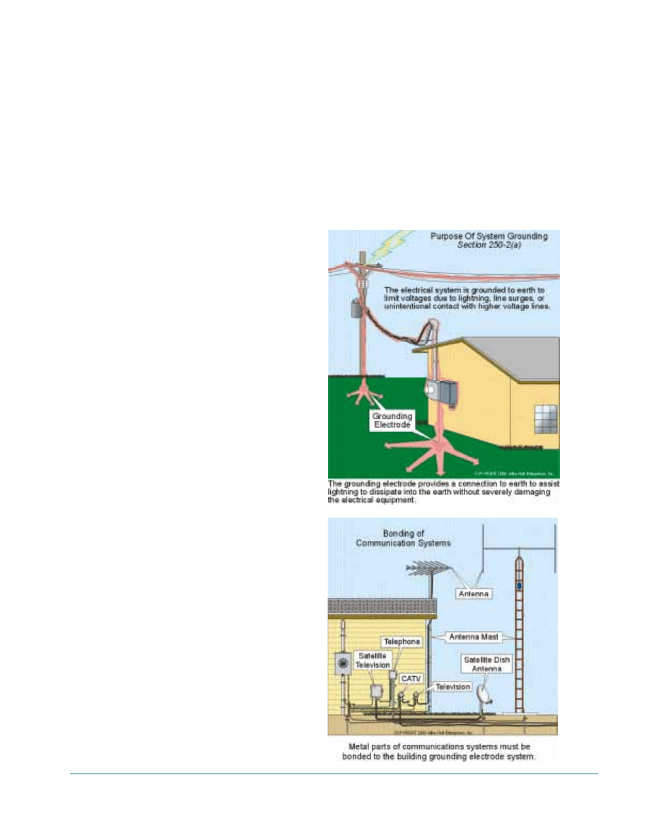
Earth Grounding [250-2(a)]
Earth grounding is the intentional connection
to earth through a ground connection or connec-
tions of sufficiently low impedance to prevent
the destruction of electrical components, as well
as electric shock that can occur from superim-
posed voltage from lightning, voltage transients,
and contact with higher voltage systems. In addi-
tion, earth grounding helps prevent the build-up
of static charges on equipment and material as
well as establishing a zero voltage reference
point to ensure the proper performance of sensi-
tive electronic and communications systems
equipment, Fig. 5-6.
18
Guide to Low-Voltage & Limited Energy Systems
FIGURE
5-3
FIGURE
5-5
FIGURE
5-5
Author’s Comment: Failure to
properly earth ground communica-
tions systems has led to $500 mil-
lion dollars of property or equip-
ment damage annually due to light-
ning and power surges, according to
insurance industry data.
The impedance of the earth ground is depen-
dent on the resistance of the electrodes, the ter-
mination resistance, contact resistance of the
electrodes to the adjacent earth, and the resis-
tance of the body of earth surrounding the elec-
trodes. Most of the resistance comes from the
resistivity of the soil, which the electrode is in
contact with. Minerals, moisture content and
temperature affect soil resistivity.
Earth Grounding and Bonding of Communications
Systems
The National Electrical Code required earth
grounding of telecommunications [800-40(b)],
antennas and lead-in cables [810-21(f)], CATV
[820-40(b)], and network-powered broadband
communications systems [830-40(b)]. This is
accomplished by bonding the communications
systems to the building earth ground, Fig. 5-7.
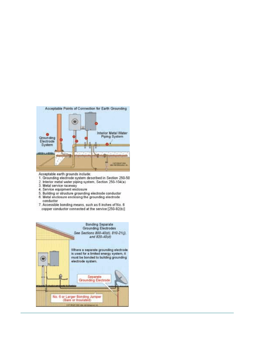
The communications systems must be bonded
to any of the following earth ground locations,
Fig. 5-8:
1. Building or structure grounding elec-
trode system as described in Section
250-50.
2. Interior metal water pipe meeting the
requirements of Section 250-104(a).
The limitation of 5 feet in Section 250-
50 does not apply.
3. Metal service raceway.
4. Service equipment enclosure.
5. Building or structure grounding elec-
trode conductor.
6. Metal enclosure enclosing the building
or structure grounding electrode
conductor.
7. Accessible bonding means such as six
inches of No.6 copper conductor con-
nected to the service equipment or
raceway [250-92(b)].
Author’s Comment: When an elec-
trode such as a ground rod is
installed for the communications
systems, it must be bonded with a
No.6 copper or larger bare or insu-
lated conductor to the grounding
electrode system at the building or
structure served, Fig. 5-9.
Termination. Earth grounding termination to
the grounding electrode must be done by
exothermic welding, listed lug, listed pressure
connector, or by listed clamp. Earth grounding
Unit 5. Understanding Grounding Requirements
19
FIGURE
5-6
FIGURE
5-7
buried in the earth must be listed for direct burial
and marked “DB” [800-40(c), 820-40(c), and
830-40(c)].
Metal Raceway. If the earth conductor is rnn
in a metal raceway, then both ends of the metal
raceway must be bonded to the earth-grounding
conductor F800-40(a)(5), 810-21(d), 820
40(a)(5), and 830-40(a)(5)].
20
Guide to Low-Voltage & Limited Energy Systems
FIGURE
5-5
FIGURE
5-5

Unit 6. Earth Grounding of Communications Systems
21
All of the following communications systems
must be earth grounded. The most effective
method is to bond them to a common point at
the building grounding electrode system.
Low-Voltage Lighting - Article 411
Listed low-voltage lighting systems that com-
ply with Article 411 are not required to be
grounded [411-5(a)].
Intrinsically Safe Systems - Article 504
Safety Ground - Intrinsically safe apparatus,
associated apparatus, cable shields, metal enclo-
sures, and raceways must be safety grounded by
the use of an equipment grounding conductor
[504-50(a)]. In addition, locknut-bushings and
double-locknuts shall not be depended upon for
bonding purposes, but bonding jumpers with
proper fittings or other approved means of bond-
ing shall be used. Such means of bonding shall
apply to all intervening raceways, fittings, boxes,
enclosures, etc., between Class I hazardous loca-
tions and the point of grounding for service
equipment or point of grounding of a separately
derived system [504-60].
Earth Ground - Where connection to a
grounding electrode is required by the equipment
instructions, the grounding electrode shall be as
specified in Section 250-50. A separate ground
rod cannot be used for this purpose, if electrodes
specified in Section 250-50 are available [504-
50(b)].
Sound (Audio) Systems - Article 640
Safety Ground - Circuits Not Over 50 Volts -
Safety or earth grounding is not required for
metal raceways and enclosures that contain
sound circuits that operate at less than 50 volts
[250-112(i)] unless the cables are exposed to
lightning [725-54(c)].
System Ground - Circuits 60 Volts – Sound
circuits that operate at 60 volts to ground must
have their metal enclosures and raceways
grounded in accordance with Section 250-30 for
separately derived systems. In addition an equip-
ment grounding conductor must be provided in
accordance with Section 530-72(b) [640-7].
Safety Ground - Circuits Over 50 Volts – Safe-
ty or earth grounding is required for metal race-
ways and enclosures that contain sound circuits
that operate at over 50 volts.
Low- Voltage circuits less than 50 volts -
Article 720
Grounding is not required for low-voltage sys-
tems that operate at less than 50 volts, unless the
primary exceeds 150 volts to ground, the prima-
ry supply is ungrounded, or the secondary con-
ductors are installed as overhead conductors out-
side the building [720-10 refers to 250-20(a)].
Class 1, 2 and 3 Circuits - Article 725
Safety Ground - Circuits Over 5O Volts –
Class 1 circuits that operate at over 50 volts must
have their metal enclosures and raceways
grounded to clear fault current in accordance
with Article 250 U25-6].
Safety Ground - Circuits Not Over 50 Volts
–Safety grounding is not required for metal
equipment or raceways that contain circuits that
operate at not over 50 volts [250-20(a), 250-86,
and 250-112(i)], [see Fig. 5-4, p.18].
Unit 6. Earth Grounding of
Communications Systems
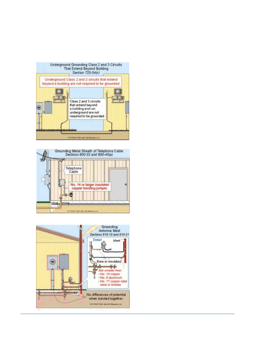
Earth Ground - Shielded Class 2 or 3 twisted-
pair conductors that extend beyond the building
structure and are exposed to lightning must be
earth grounded in accordance with Section 800-
33 for telecommunications systems and coaxial
cable must be grounded in accordance with Sec-
tion 820-33 for CATV systems [725-54(c)].
Author’s Comment: Class 2 and
Class 3 cables installed outdoor not
exposed to lightning (installed
underground) do not need to be
grounded, Fig. 6-1.
Fire Alarm Signaling Systems - Article 760
Safety Ground - Circuits Over 50 Volts -Metal
equipment, metal raceways, and cables contain-
ing nonpower-limited fire alarm circuit over 50
volts must be installed using Chapter 3 wiring
method and must be safety grounded in accor-
dance with Article 250 [760-6].
Safety Ground - Circuits Not Over 50 Volts -
Power-limited fire alarm circuits that operate at
less than 50 volts are not required to be safety
grounded [250-112(i)].
Telecommunications (Telephone) Systems -
Article 800
Earth Ground - The metallic sheath of tele-
phone cable and primary protectors must be
grounded to the earth (electrode) as close as
practicable to the point of entrance of the phone
cable to the building or structure [800-331. The
earth grounding is accomplished by bonding the
telephone’s grounding block to an acceptable
earth ground with a No.14 or larger insulated
copper conductor run in as straight a line as
practicable [800-40(a)], Fig. 6-2.
Outdoor Antenna, Satellite, and Other Receiving
Systems [Article 8101
Proper grounding of antenna mast and lead-in
cables is somewhat effective in protecting receiv-
ing equipment from voltage surges, as well as
voltage transients that result from lightning.
Mast - The metal structure that supports radio,
HAM, television and satellite receiving antennas
must be grounded to an acceptable earth ground
[810-15] with a No.10 copper bare or insulated
conductor run in as straight a line as practicable
[810-21], Fig. 6-3.
22
Guide to Low-Voltage & Limited Energy Systems
FIGURE
6-2
FIGURE
6-1
FIGURE
6-3
Author’s Comment: If the mast is
not properly grounded, the Low
Noise Block (LNB), as well as the
dc rotor motors that control the
positioning larger satellite dishes
often will be destroyed by voltage
surges caused by nearby lightning
strikes.
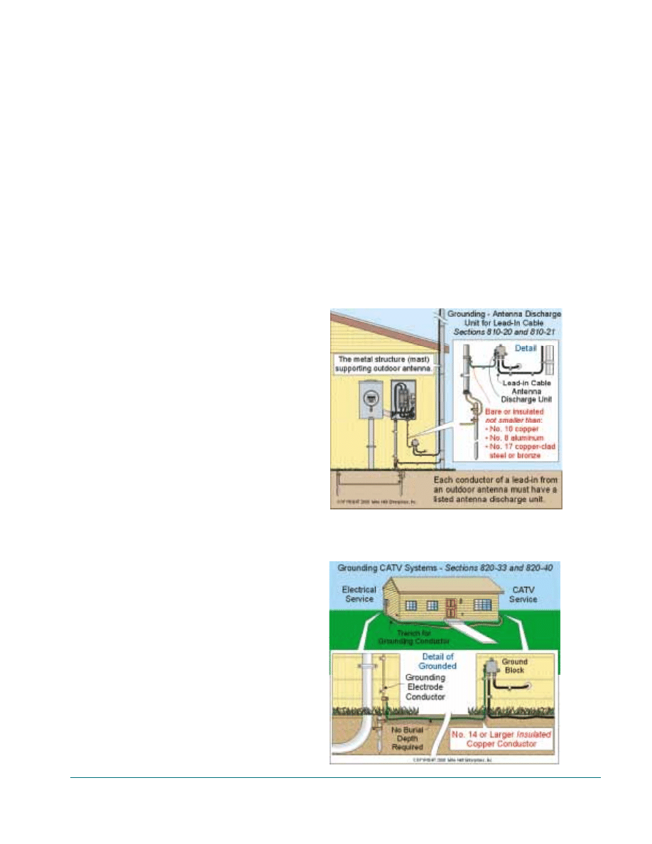
Lead-in Cable – Each conductor (coaxial,
control, and signal conductors) of a lead-in from
an “outdoor antenna” must be provided with a
listed antenna discharge unit (grounding block).
The antenna discharge unit must be located out-
side or inside as near as practicable to the
entrance of the conductors to the building and it
must not be located near combustible material
[810-20]. The discharge unit must be grounded
to an acceptable earth ground [810-21(f)] with a
No. 10 copper bare or insulated conductor run in
as straight a line as practicable [810-21], Fig. 6-
4.
Author’s Comment: If each con-
ductor of a lead-in from an outdoor
antenna is not properly earth
grounded, the receiver can be
destroyed by voltage surges caused
by nearby lightning strikes.
CATV Systems [Article 820]
Earth Ground – The metallic sheath of CATV
cable entering a building or structure must be
grounded to the earth as close as practicable to
the point of entrance to the building or structure
[820-33]. The earth grounding is accomplished
by bonding the Cat’s grounding block to an
acceptable earth ground with a No.14 or larger
insulated copper conductor run in as straight a
line as practicable to the earth [820-40(a)].
Author’s Comment: CATV sys-
tems are often terminated at a loca-
tion that is not near the electrical
service, and since most new homes
have nonmetallic water piping sys-
tems, CATV systems require that an
insulated No. 14 grounding con-
ductor run to an acceptable earth
ground, Fig. 6-5.
CCTV and MATV Systems
Earth Ground – Closed circuit television
(CCTV) and master antenna television (MATV)
circuits within a building do not have to be
grounded to the earth. However coaxial cable
that extends beyond the building structure and is
exposed to nearby lightning must be earth
grounded [810-2]. The metal sheath of coaxial
cables (exposed to nearby lighting) that enters a
building or structure must be grounded to an
acceptable earth ground as close as practicable to
the point of entrance to the separate building or
structure [820-33]. The earth grounding is
accomplished by bonding the CCTV grounding
block to an accept able earth ground with a
Unit 6. Earth Grounding of Communications Systems
23
FIGURE
6-6
FIGURE
6-5
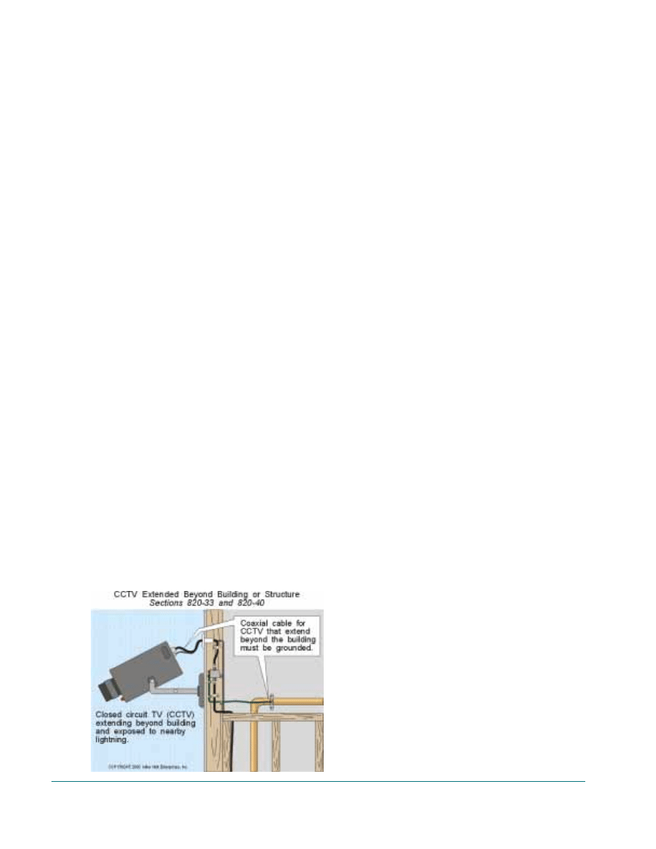
No.14 or larger insulated copper conductor run
in as straight a line as practicable [820-40(a)],
Fig. 6-6.
Network-Powered Broadband Communications
Systems - Article 830
Earth Ground Cable – The metallic sheath of
network-powered broadband communications
systems cable entering a building or structure
must be grounded to the earth as close as practi-
cable to the point of entrance to the building or
structure [830-33]. The earth grounding is
accomplished by bonding the NPBCS cable
(grounding block) to an acceptable earth ground
with a No.14 copper to a maximum No.6 copper
conductor (depending on the current-carrying
capacity coaxial shield) run in as straight a line
as practicable 1830-401.
Earth Ground Metal Raceway – Metal race-
ways used for network power broadband
entrance cable must be bonded to an acceptable
earth ground with a No.14 copper to a maximum
No.6 copper conductor depending on the current-
carrying capacity coaxial shield [830-40 and
830-43(c) Exception].
24
Guide to Low-Voltage & Limited Energy Systems
FIGURE
6-6
Unit 7. General Wiring Requirements
25
The general wiring method requirements con-
tained in Article 300 do not apply to low-voltage
or limited-energy system, unless a specific refer-
ence is made in Chapter 7 [725-3, 760-3 and
770-31 or Chapter 8 [90-3] to a specific Section
in Article 300.
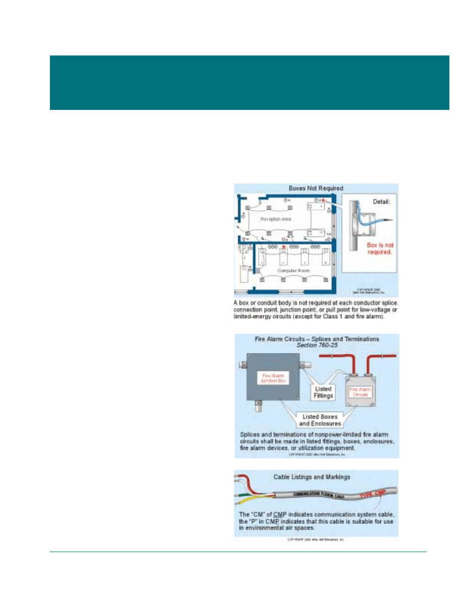
Boxes Not Required
A box or conduit body is not required at each
conductor splice, connection point, junction
point, or pull point for low-voltage and limited-
energy circuits, Fig. 7-1.
Author’s Comment: Low-voltage
and limited-energy devices in fire
resistant walls, floors, and ceiling,
must be installed in metal outlet
boxes or fire rated nonmetallic out-
let boxes [300-21]. For example,
fire rated outlet boxes must be used
when cable or phone devices are
installed in fire rated residential
garage walls [300-21].
Boxes Required
Outlet boxes must be used for Class I circuits
[725-25] and fire alarm circuits [760-25, 760-
30(a) and 760-52(b)(1)], Fig. 7-2.
Cable Listing and Marking
Low-voltage and limited-energy cables
installed within a building must be listed as
being suitable for the purpose, Fig. 7-3.
Table 7-1 indicates acceptable cables for each
type of system.
Unit 7. General Wiring
Requirements
FIGURE
7-1
FIGURE
7-2
FIGURE
7-3
26
Guide to Low-Voltage & Limited Energy Systems
CL2 CL3
FPL NFPL OF CM MP CATV BL BM Chapter 3
Article 720 – Circuits
Less than 50 volts
•
Article 725 – Class 1
Remote-Control, Signaling
•
Article 725 – Class 2
Remote-Control, Signaling
•
•
•
Article 725 – Class 3
Remote-Control, Signaling
•
•
Article 760 – Fire Alarm
Power-Limited Circuits
•
Article 760 – Fire Alarm
Power-Limited Circuits
•
•
•
•
Article 770 – Optical Fiber Cables
•
Article 800 – Telecommunications
Systems
• •
Article 820 – Cable -
Television (CATV)
•
•
Article 820 – Network Low-
Powered Broadband
•
Article 820 – Network Medium-
Powered Broadband
•
• •
•
CL2 - Class 2 Cable [725-71]
OF - Optical Fiber Cable [770-71]
CL3 - Class 3 Cable [725-71]
MP - Multipurpose Cable (Coaxial) [800-50]*
FPL - Power-Limited Fire Alarm Cable [760-71]
CATV - CATV Cable [820-53]*
NFPL - Nonpower-Limited Fire Alarm Cable [760-31]
BL - Broadband Low-Power Cable [830-55]*
CM - Communications Cable [800-53]*
BM - Broadband Medium-Power Cable [830-55]*
* Listing and marking are not required where the length of the cable within the building measured from its
point of entrance does not exceed 50 feet [800-50 Exc. 3, 820-50 Exc. 3, and 830-55(c) Exc. 4].
The Code may require additional marking for
low-voltage and limited-energy cables, depend-
ing on the intended use of the cable such as:
The P suffix stands for plenum rating. Plenum
cables are listed for use in environmental air
space (dropped ceiling space used for return air)
and they have adequate fire-resistant and low
smoke-producing characteristics.
• The R suffix stands for riser rating. Riser
cables are listed for use in vertical shafts (risers)
and they have fire-resistant characteristics to pre-
vent the carrying of fire from floor to floor.
• The X suffix indicates that a cable is listed
for use in dwellings and in raceways.
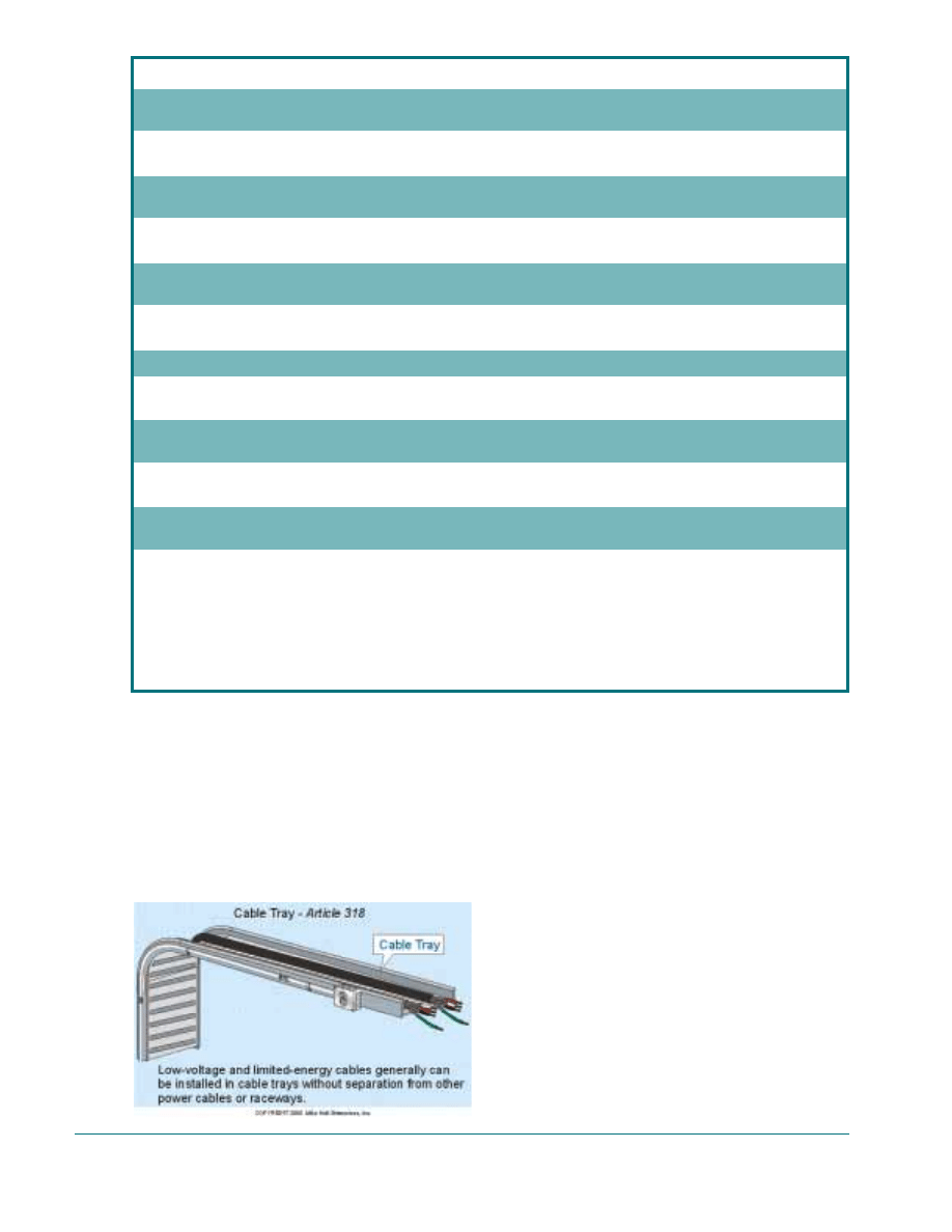
Cable Tray [Article 318]
A cable tray system is a unit or assembly of
units or sections, and associated fittings, forming
a structural system used to securely fasten or
support cables and raceways. The following rules
must be complied with when installing low-volt-
age or limited-energy cable within a cable tray,
Fig. 7-4:
• CATV Cables [Article 820] - The NEC does
not contain any reference to permit the installa-
tion of CATV, MATV, or CCTV cables within a
cable tray [3l8-3(a)].
FIGURE
7-4
TABLE
7-1
• Class] Control and Signaling Conductors
[Article 725] - Class 1 control and signaling
conductors must be installed using a Chapter 3
wiring method in accordance with the require-
ments of Article 318 [725-3(d)].
• Class 2 and Class 3 Cables [Article 725] -
Class 2 and Class 3 cables marked: PLTC, MPP
MPR, MPG, MR CMP CMR, CMG, CM, CL3P,
CL3R, CL3, CL2l, CL2R, or CL2 can be
installed in cable trays [318-3(a), 725-3(d), 725-
61(c), and 725-71].
• Fire Alarm Conductors [Article 760] - Non-
power-limited fire alarm circuit conductors must
be installed using a Chapter 3 wiring method in
accordance with the requirements of Article 318
[318-3(a) and 760-28(c)].
• Instrumentation Tray Cables Type ITC [Arti-
cle 727] - Instrumentation tray cables are per-
mitted to be installed in cable trays at industrial
establishments [318-3(a), 727-3, and 727-4(1)].
• Network-Powered Broadband Communica-
tions Systems - The NEC does not contain any
reference to permit the installation of BL or BM
cables in cable trays [318-3(a)].
• Optical Fiber Cables [Article 770] - Any
listed optical fiber cable can be installed in a
cable tray [318-3(a) and 770-52(a)].
• Radio and Television Cables [Article 810] -
The NEC does not contain any reference to per-
mit the installation of radio and television cables
in cable trays.
• Sound (Audio) Systems [Article 640] - Class
2 and Class 3 cables marked: PLTC, MPP, MPR,
MPG, MR, CMP, CMR, CMG, CM, CL3P,
CL3R, CL3, CL2R, CL2R, or CL2 can be
installed in cable trays [318-3(a), 640-3(c),
7253(d) 725-61(c), and 725-71].
• Telecommunications Cables [Article 800] -
Telecommunications cables marked: MPP, MPR,
MPG, MR, CMR, CMR, CMG, and CM can be
installed in cable trays [318-3(a) and 800-52(d)].
Author’s Comment: Low-voltage
and limited-energy cables can be
installed in cable trays without sep-
aration from power raceways or
cables, see the “Separation” section
in this Chapter.
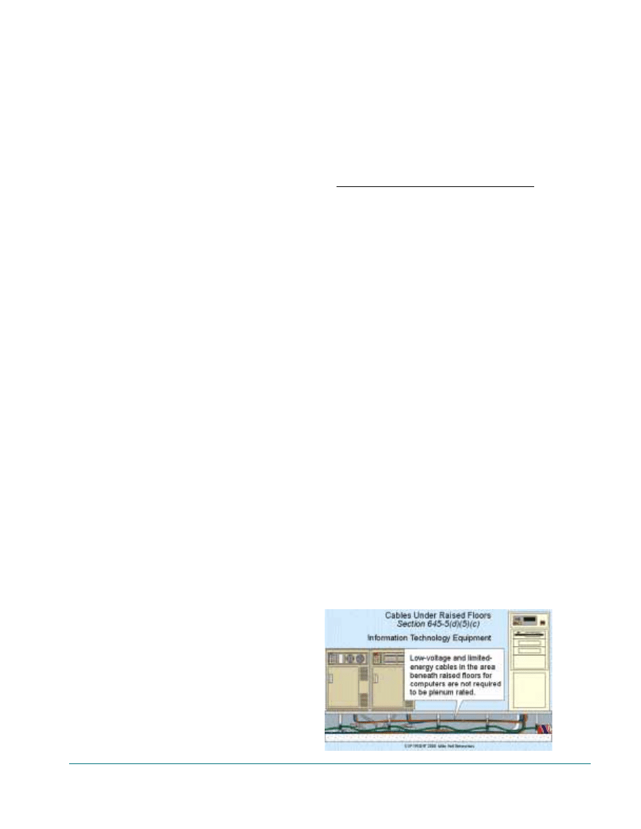
Computer Rooms
The general requirement is that cables
installed within raised floors of computer rooms
shall be listed for data processing rooms and be
marked Type DP. Type DP cable is constructed
to have adequate fire-resistance characteristics
suitable for use under a computer room raised
floor [645-5(d)]. The following types of low-
voltage and limited-energy cables are also per-
mitted to be used beneath computer room raised
floors, and these cables are not required to be
Type DP or plenum rated [645-5(d)(5)(c)], Fig.
7-5:
System
Cable Type
• CATV, MATV, CCTV
Type CATV
• Control and Signaling
Type CL2, CL3,
and PLTC
• Optic Fiber
Types OFC and OFN
• Fire Alarm
Types NPLF and FPL
• Network-Powered
Broadband
No Code Rule
• Sound (Audio)
Type CL2, CL3,
and PLTC
• Telecommunications
Types CM and MP
Author’s Comment: The NEC
does not require the grounding of
the metal structure that supports a
raised computer floor. However, a
green insulated single conductor
cable No. 4 and larger marked “For
use in cable trays” or “For CT use”
can be installed within a raised floor
area for high-frequency RF bonding
of the metal raised floor pedestals
[645-5(d)(5)(c)]. This technique is
used to minimize radio frequency
interference (RFI), often known as
“electrical noise,” that can disrupt
communications circuits.
Unit 7. General Wiring Requirements
27
FIGURE
7-3
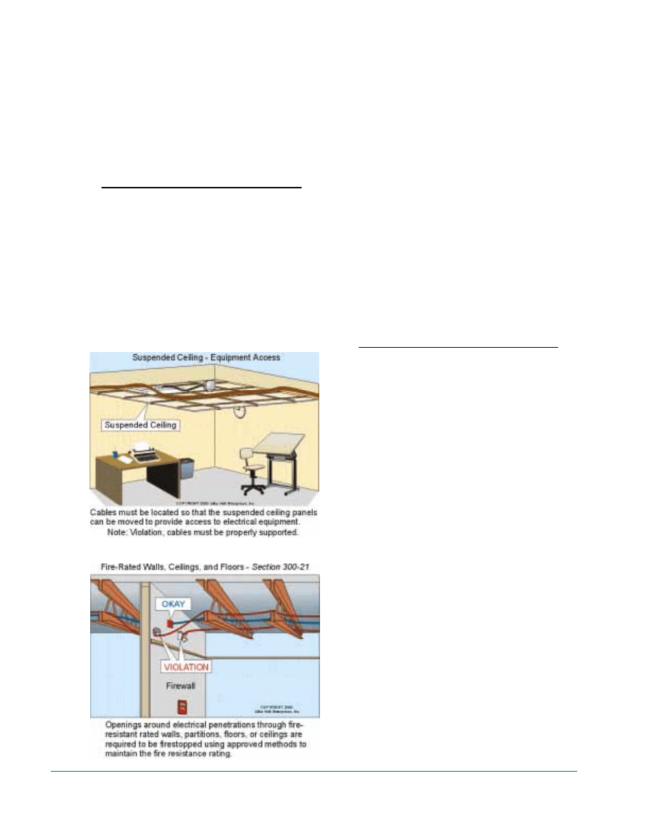
Equipment Access
Access to equipment must not be prohibited
by an accumulation of cables that prevent the
removal of suspended ceiling panels. Cables
must be located so that the suspended ceiling
panels can be moved to provide access to electri-
cal equipment, Fig. 7-6.
Note: See the support section in this Chapter
for the requirements for proper cable supports.
System
Section
• CATV MATV, CCTV
820-5
• Control and Signaling
(Class 2 and 3)
725-5
• Optical Fiber
770-7
• Fire Alarm
760-5
• Network-Powered Broadband
830-6
• Radio and Television
No Code Rule
• Sound (Audio)
640-5
• Telecommunications
800-5
Fire Rated Walls/Ceilings/Floors
Low-voltage and limited-energy cables must
be installed so that they don’t increase the spread
of fire or smoke [300-21]. This means that open-
ings in fire-rated walls, floors, and ceilings must
be sealed with an approved fire-stop material.
The installation of fire-stop materials must be
done in accordance with the specific instructions
supplied by the manufacturer for the specific
type of wiring method (raceway or cable), and
construction material (drywall, brick, etc.), Fig.
7-7.
Author’s Comment: When low-
voltage and limited-energy devices
are installed fire resistant walls,
floors, and ceiling, metal outlet
boxes or fire rated nonmetallic out-
let boxes must be used to maintain
the fire resistant rating of the assem-
bly, Fig. 7-7.
System
Section
• CATV
820-3(b)
• Control and Signaling
(Class 2 and 3)
725-3(a)
• Optical Fiber
770-3(a)
• Fire Alarm
760-3(a)
• Network-Powered Broadband
830-3(a)
and 830-58(b)
• Sound (Audio)
640-3(a)
• Telecommunications
800-52(b)
Author’s Comment: Many times
fire stopping is enforced by the
structural inspector during framing
inspection,
and local building
Codes often contain specific fire-
stopping requirements.
Identification
Fire Alarm Circuits [Article 760] - Fire alarm
circuits must be identified at all terminal and
junction locations. The identification must be in
a manner that will prevent unintentional interfer-
ence with the fire alarm circuits during testing
and servicing [760-10], Fig. 7-8.
28
Guide to Low-Voltage & Limited Energy Systems
FIGURE
7-6
FIGURE
7-7
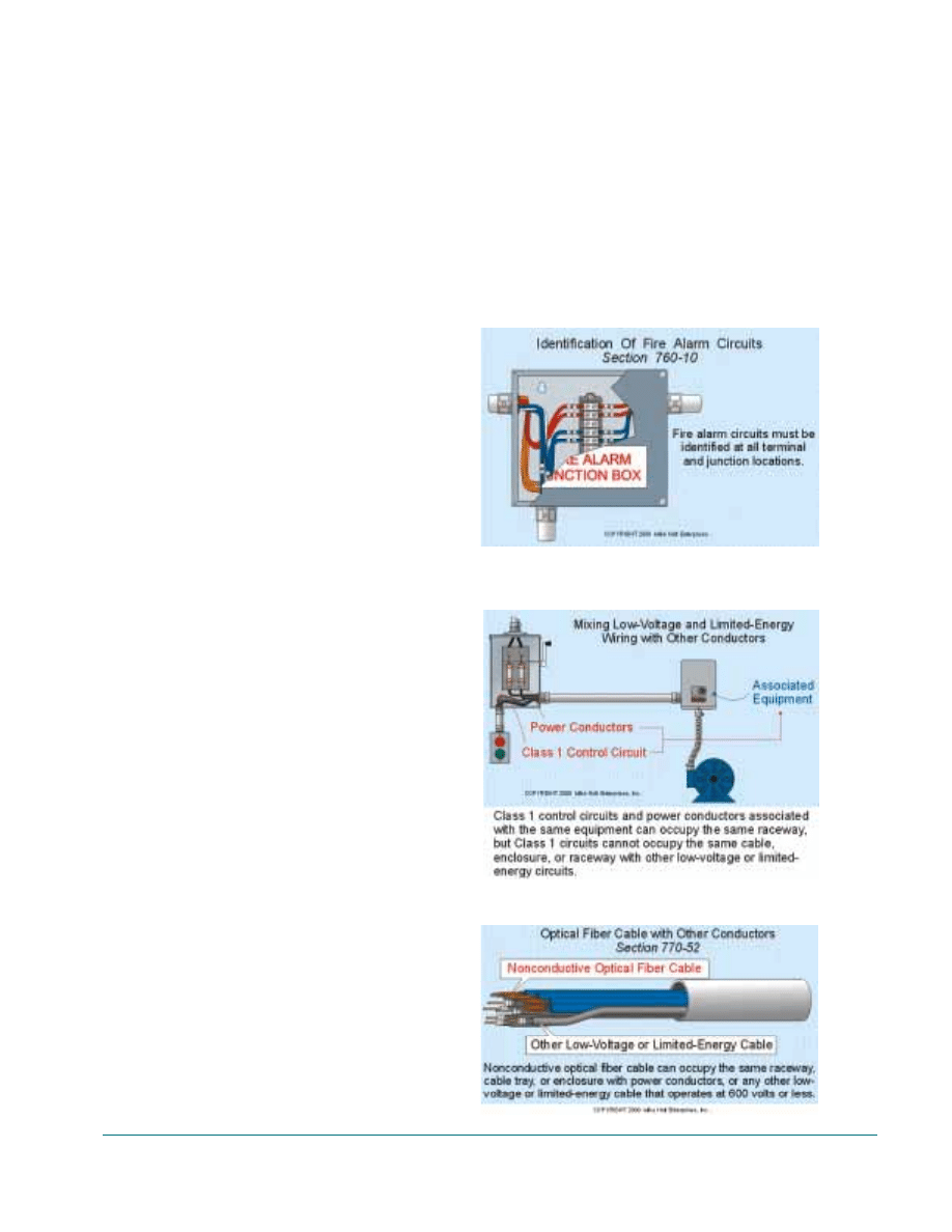
Intrinsically Safe Systems [Article 504] -
Permanently affixed labels with the wording
“Intrinsic Safety Wiring” must be placed on
raceways containing intrinsically safe cables.
The labels must be visible after installation and
placed so that they may be readily traced through
the entire length of the installation in both the
classified as well as the unclassified area [504-
80(b)].
Lighting Fixtures, Recessed
Low-voltage incandescent recessed fixtures
must have thermal protection and be identified as
thermally protected [410-65(c)]. In addition,
low-voltage fixtures that are “Type IC” can be
installed in contact with thermal insulation [410-
66(b)].
Manhole Installations
Low-voltage and limited-energy cables
installed in manholes shall be installed in accor-
dance with Section 370-52 Cabling Work Space,
and Section 370-55 Access to Manholes.
Mixing Low-Voltage and Limited-Energy Cables
and Conductors
• Class 1 Conductors – Class 1 control cir-
cuits and power conductors associated with the
same equipment can occupy the same raceway,
but Class 1 circuits cannot occupy the same
cable, enclosure, or raceway with other low-volt-
age or limited-energy circuits, Fig. 7-9.
• Optical Fiber Cable – Nonconductive opti-
cal fiber cable can occupy the same raceway,
cable tray, or enclosure with power, or any other
low-voltage or limited-energy cable that operates
at 600 volts or less [770-52], Fig. 7-10.
• Nonpower-Limited Fire Alarm Conductors –
Nonpower-limited fire alarm conductors can be
installed in the cable, enclosure, or raceway with
power conductors used solely for supplying
power to the equipment to which fire alarm con-
ductors are connected [760-26 and 760-28(c)].
• Other Low-Voltage and Limited-Energy
Conductors - To provide protection to those who
might come in contact with low-voltage or limit-
ed-energy wiring, conductors for these systems
must be separated from power, Class 1, nonpow-
er-limited fire alarm conductors so that they are
not accidentally energized by the higher voltage
power conductors.
Unit 7. General Wiring Requirements
29
FIGURE
7-8
FIGURE
7-9
FIGURE
7-10
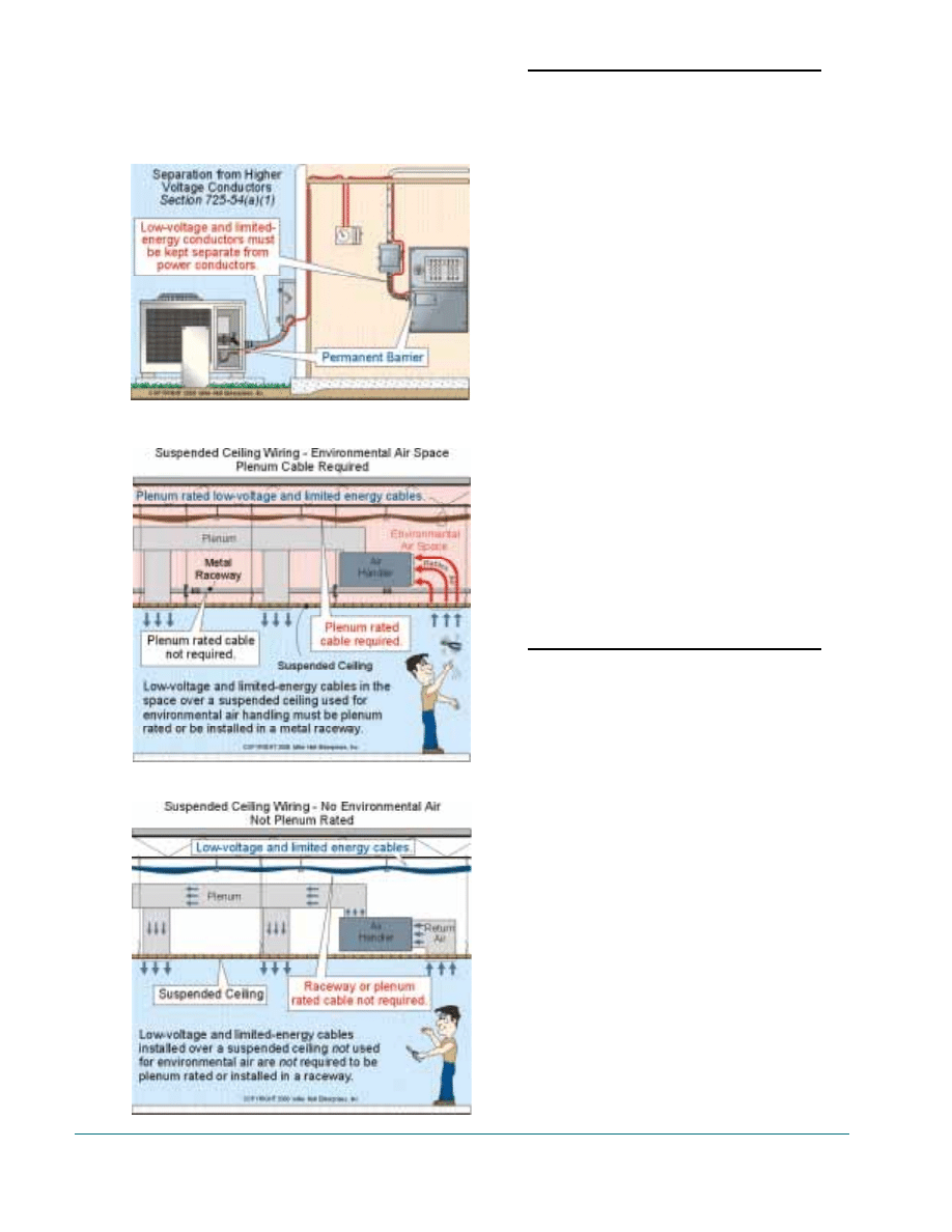
The following Code sections prohibit the mix-
ing of low-voltage and limited-energy conduc-
tors with power, Class 1, or nonpower-limited
fire alarm circuit conductors:
System
Sections
• CATV, MATV, CCTV
820-lO(f)(1)
• Control and Signaling
(Class 2 and 3)
725-54(a)(1)
Fig. 7-11
• Fire Alarm (Power-Limited)
760-54(a)(1)
• Intrinsically Safe
504-30(a)(2)
• Instrument Tray Cable
727-5
• Network-Powered
(medium power)
830-58(c)
• Radio and Television 810-18(c) and 810-70
• Sound (Audio)
640-9(c)
• Telecommunications
800-52(a)(1)
Exceptions to the above Code sections permit
power conductors to terminate onto listed low-
voltage and limited-energy equipment, if the
power conductors maintain a minimum of 0.25
inch separation from the low-voltage and limit-
ed-energy conductors.
Plenum Cable
Low-voltage and limited-energy cables
installed in ducts, plenums, and dropped ceiling
spaces used to move environmental air must be
either plenum rated or installed in a metal race-
way, Fig. 7-12.
System
Sections
• CATV, MATV, CCTV
820-51(a)
• Control and Signaling
(Class 2 and 3)
725-61(a)
• Fire Alarm
760-61(a)
• Network-Powered Broadband
830-54(b)
and 830-55(b)
• Optical Fiber
770-53(a)
• Radio and Television
No Code Rule
• Sound (Audio)
640-9(c) and 725-61(a)
• Telecommunications
800-53(a)
Note: The PLTC cable is not manufac-
tured as a plenum rated cable.
Author’s Comment: Where cable
tics are used to secure, low-voltage
and limited-energy cables must be
plenum rated!
30
Guide to Low-Voltage & Limited Energy Systems
FIGURE
7-11
FIGURE
7-12
FIGURE
7-13
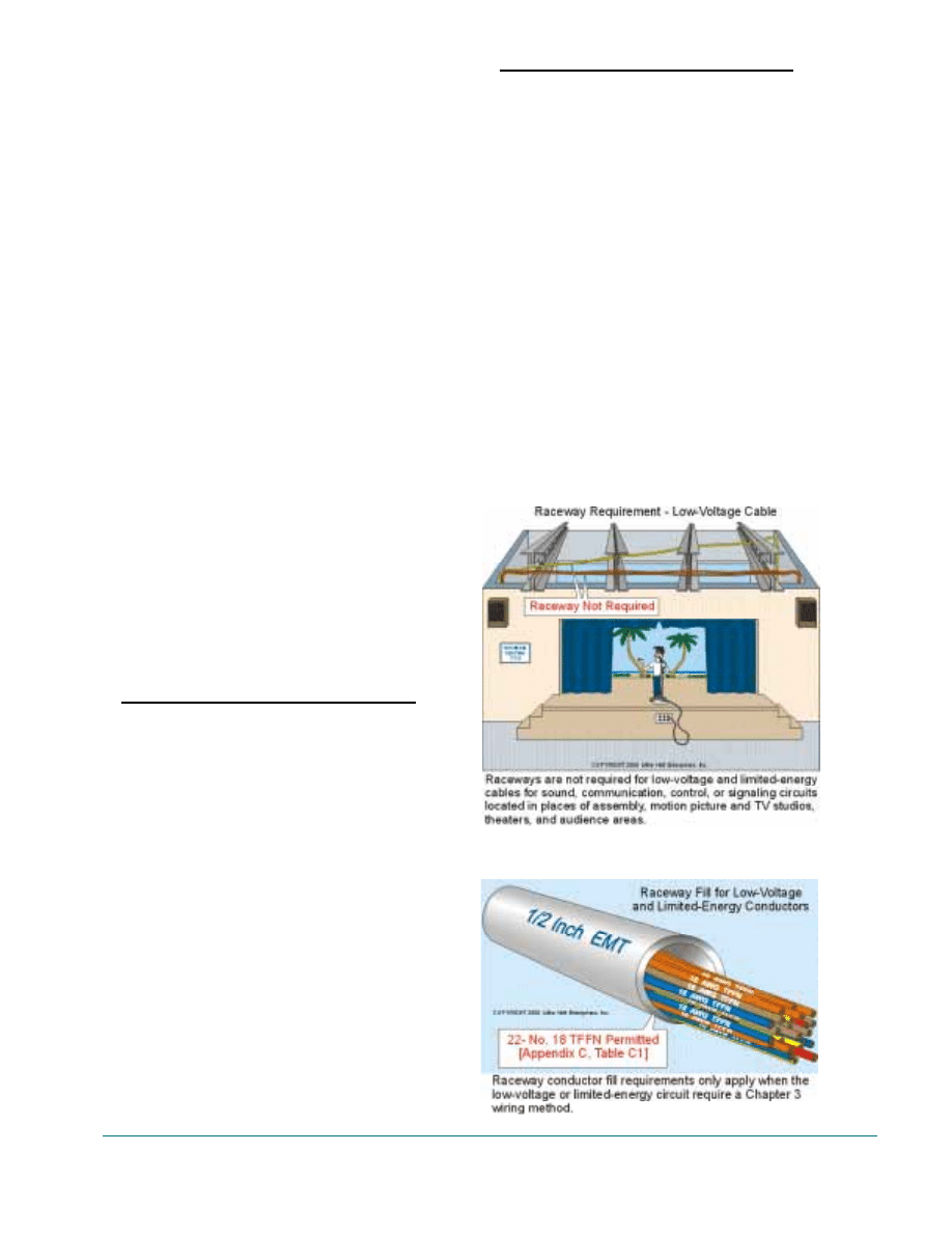
Plenum Rating Not Required – Low-voltage
and limited-energy cables are not required to be
plenum rated when installed in the space over a
suspended ceiling that is not used for air han-
dling. In addition, low-voltage and limited-ener-
gy cables do not have to be plenum rated if they
are installed in habitable rooms or areas of a
building the primary purpose of which is not air
handling [300-22(c) Exception No.31, Fig. 7-13.
Plenum Raceways
Nonmetallic raceways installed in ducts,
plenums, and other spaces used for environmen-
tal air must be listed for plenum spaces [770-6
and 800-51], and the cables installed in the non-
metallic raceways must be plenum rated [770-
53(a) and 800-53(a)].
Author’s Comment: Listed non-
metallic plenum rated raceways
must be installed in accordance with
Article 331 - Electrical Nonmetallic
Tubing [770-6 and 800-48]. Howev-
er, the NEC does not make any ref-
erence to plenum rated raceways in
Articles 725, 760, 810, 820 or 830.
Raceway Not Required - The following low-
voltage and limited-energy cables are not
required to be installed in raceways, Fig. 7-14:
System
Section
• CATV
90-3
• Control and Signaling
(Class 2 and 3)
725-3
• Optical Fiber Cables
770-3
• Power-limited Fire Alarm Cables
760-3
• Radio and Television
90-3
• Sound (Audio) Systems
(Class 2 or 3 Cables)
640-23
Raceway Required – The following low-volt-
age and limited-energy system must be installed
in a Chapter 3 wiring method, and raceway con-
ductor fill limitations apply [300-17].
System
Section
• Circuits in Compliance
with Article 720
300-17
• Class 1 Control and Signaling
725-28
• Class 2 and 3 Control
and Signaling
725-8(b)*
• Fire Alarm Nonpower-Limited
760-28
• Fire Alarm Power-Limited
760-52(b)*
• Optical Fiber Cables
(installed with power conductors)
770-6
• Sound (Audio)
640-23
• Telecommunications
800-48
*Class 2 and 3 cables for control and signal-
ing, and power- limited fire alarm cables subject
to physical damage must be protected
The requirements of raceway conductor fill
only apply when the low-voltage or limited-
Unit 7. General Wiring Requirements
31
FIGURE
7-14
FIGURE
7-15
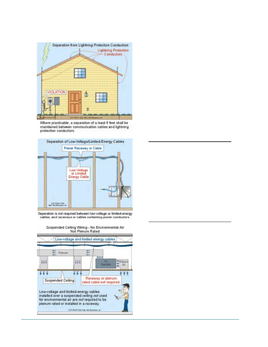
energy circuit utilizes Chapter 3 wiring methods
(such as Class 1 conductors for control, signal-
ing, or other uses such as sound systems), Fig. 7-
15.
Author’s Comment: In order to
maintain cable performance, many
contractors install low-voltage and
limited-energy cables in accordance
with the BICSI Cabling Installation
Manual (Chapter 4). This installa-
tion guideline suggests that raceway
runs be limited to 100 feet, no more
than two 90-degree bends be
installed in one run, and also recom-
mends a maximum pull force of 25
pounds for each Category 5 cable
and 100 pounds for each optical
fiber cable.
Separation from Lightning Protection Conductors
Where practicable, a separation of at least 6
feet shall be maintained between communica-
tions cables (NEC Chapter 8) and lightning pro-
tection conductors, Fig. 7-16.
System
Section
• CATV
820-10(f)(3)
• Network-Powered Broadband
830-10(i)(3)
• Radio and Television
810-18
• Telecommunications
800-13
Separation from Raceways or Cables
Two inches of separation is required between
low-voltage or limited-energy conductors and
power conductors. However, separation is not
required between low-voltage or limited-energy
cables, and raceways or cables containing power
conductors, Fig. 7-17.
System
Sections
• CATV, MATV, CCTV
820-52(a)(2)
Exception No.1
• Control and Signaling
(Class 2 and 3)
725-54(a)(3)
Exception No.1
• Fire Alarm
760-54(a)(3)
Exception No.1
• Intrinsically Safe
504-30(a)(2)
Exception No.1
• Network-Powered Broadband 830-58(a)(2)
Exception No. I
• Radio and Television
810-18(b)
Exception No.1
• Telecommunications
800-52(a)(2)
Exception No.1
32
Guide to Low-Voltage & Limited Energy Systems
FIGURE
7-16
FIGURE
7-17
FIGURE
7-18
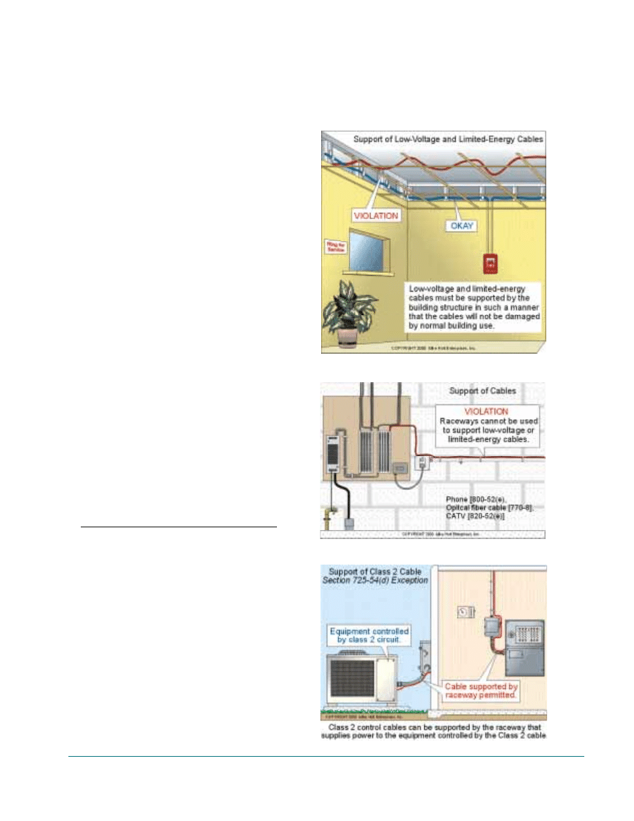
Note: Outside buildings and similar structure
power conductors must maintain 4 inches of sep-
aration from low-voltage and communications
conductors [225-14(c) and 830-10(i)(1)].
Network-powered broadband cables installed
underground must be kept 12 inches from power
conductors.
Service Masts
Service masts can only be used for the support
of power service drop conductors [230-2381. In
addition, aerial cables for radio, TV, or CATV
cannot be attached to the electric service mast
[810-12 and 820-10(c)] and receiving antennas
cannot be attached to the electric service mast
[810-12], Fig. 7-18.
Author’s Comment: Community
antenna system coaxial cables com-
plying with Article 820 and the sup-
porting messengers shall be permit-
ted at a height of not less than 10
feet above swimming and wading
pools, diving structures, and obser-
vation stands, towers, or platforms
[230-24(d) and 680-8].
Support
Low-voltage and limited-energy cables must
be supported by the building structure in such a
manner that the cables will not be damaged by
normal building use, Fig 7-19. These cables can-
not be strapped, taped, or attached to electrical
raceways, Fig. 7-20.
System
Sections
• CATV, MATV, CCTV
820-6, 820-10(c)
and 820-52(e)
• Control and Signaling
(Class 2 and 3)
725-7 and 725-54(d)*
• Fire Alarm
760-8 and 760-54(d)
• Optical Fiber
770-8
• Network-Powered Broadband
830-7
and 830-58(d)
• Radio and Television
810-12
• Telecommunications
800-6 and 800-52(e)
* Class 2 cable can be supported to the raceway
that supplies the power to the equipment controlled
by the Class 2 cable [300-1 1(b)(2) and 725-54(d)
Exception], Fig. 7-21.
Unit 7. General Wiring Requirements
33
FIGURE
7-19
FIGURE
7-20
FIGURE
7-21

Author’s Comment: Section 300-
11(a) does not permit electrical
wiring to be secured to ceiling sup-
port wires, but it does permit inde-
pendent support wires secured at
both ends to be used for the support
of electrical wiring. Technically this
rule does not apply to low-voltage
or limited-energy cables because
there is no reference to Section 300-
11(a) in Chapter 7 or Chapter 8, Fig.
7-22.
Computer Room Raised Floors – Low-voltage
and limited-energy cables installed under the
raised floors of information technology equip-
ment rooms are not required to be secured in
place [645-5(e)]. When a cable passes through
an opening in the computer raised floor, it must
be protected against abrasions, and the opening
must minimize the entrance of debris beneath the
raised floor [645-5(b)], Fig. 7-23.
Underground Installations – The burial depth
requirements of Section 300-5 do not apply to
the following low-voltage and limited-energy
cables, except landscape lighting [Article 4111,
Fig. 7-24.
System
Section
• CATV
90-3
• Control and Signaling
(Class 2 and 3)
725-3
• Optical Fiber
770-3
• Fire Alarm
760-3
• Network-Powered Broadband
90-3
Telecommunications
90-3
34
Guide to Low-Voltage & Limited Energy Systems
Wyszukiwarka
Podobne podstrony:
Metody nauczania to?lowo i systematycznie stosowany sposób pracy nauczyciela z uczniami(1)
Metody nauczania to?lowo i systematycznie stosowany sposób pracy nauczyciela z uczniami
Guide to the installation of PV systems 2nd Edition
Antisocial Guide To Horror Film The Essential Guide For Low Bud (2)
The Sinhala writing system a guide to transliteration
Herbs for Sports Performance, Energy and Recovery Guide to Optimal Sports Nutrition
Meezan Banks Guide to Islamic Banking
NLP for Beginners An Idiot Proof Guide to Neuro Linguistic Programming
50 Common Birds An Illistrated Guide to 50 of the Most Common North American Birds
Guide to the properties and uses of detergents in biology and biochemistry
Guide To Erotic Massage
A Guide to the Law and Courts in the Empire
10 Minutes Guide to Motivating Nieznany
A Student's Guide to Literature R V Young(1)
A Practical Guide to Marketing Nieznany
Guide To Currency Trading Forex
więcej podobnych podstron