
CRUISE CONTROL SYSTEM
1993 Mitsubishi Montero
1993 ACCESSORIES & EQUIPMENT
Mitsubishi Cruise Control Systems
Montero
DESCRIPTION & OPERATION
The cruise control system is electronically and vacuum
controlled. System components include a control unit, actuator, vacuum
pump, cruise control switch, clutch pedal switch, cruise indicator
light, diode, inhibitor switch (A/T), stoplight switch, vehicle speed
sensor and A/T control unit.
The system has self-diagnostic capability. When
self-diagnostic mode is activated, each switch and sensor is checked
for defects. When cruise control system has been canceled without
using a normal cancel method, a code will be set and stored in control
unit. Codes can be retrieved to help determine which circuit is
malfunctioning.
PRELIMINARY INSPECTION
Before performing TROUBLE SHOOTING steps, inspect linkage
assembly, actuator, cables and vacuum hoses. Ensure linkage and cables
move smoothly. Ensure cables do not have excessive slack or tension.
TROUBLE SHOOTING
NOTE: For further trouble shooting information, see CHECK RESULTS
& SYMPTOM CHARTS. See Figs. 5-7.
SYSTEM CANCELS OR WILL NOT RESET AFTER CANCELLATION
1) Check trouble codes, see SELF-DIAGNOSTICS under DIAGNOSIS
& TESTING. If no trouble codes are stored, ensure cruise control can
be set.
2) If cruise control can be set, system may have canceled
because of driving on steep hills or loose wiring connection. If
cruise control still cannot be set, perform SYSTEM INPUT TESTS under
DIAGNOSIS & TESTING.
3) If SYSTEM INPUT TESTS check okay, check vacuum pump
circuit. See TEST NO. 6 under CIRCUIT TESTS. If SYSTEM INPUT TESTS do
not check okay, see INPUT CODE CHART. See Fig. 4.
ADJUSTMENTS
CRUISE CONTROL CABLE
Remove link protector. Loosen lock nut. Hold link "A" so that
it touches link "B". Adjust free play by turning adjusting nut until
free play is .04-.08" (1-2 mm). Tighten lock nut. See Fig. 1.
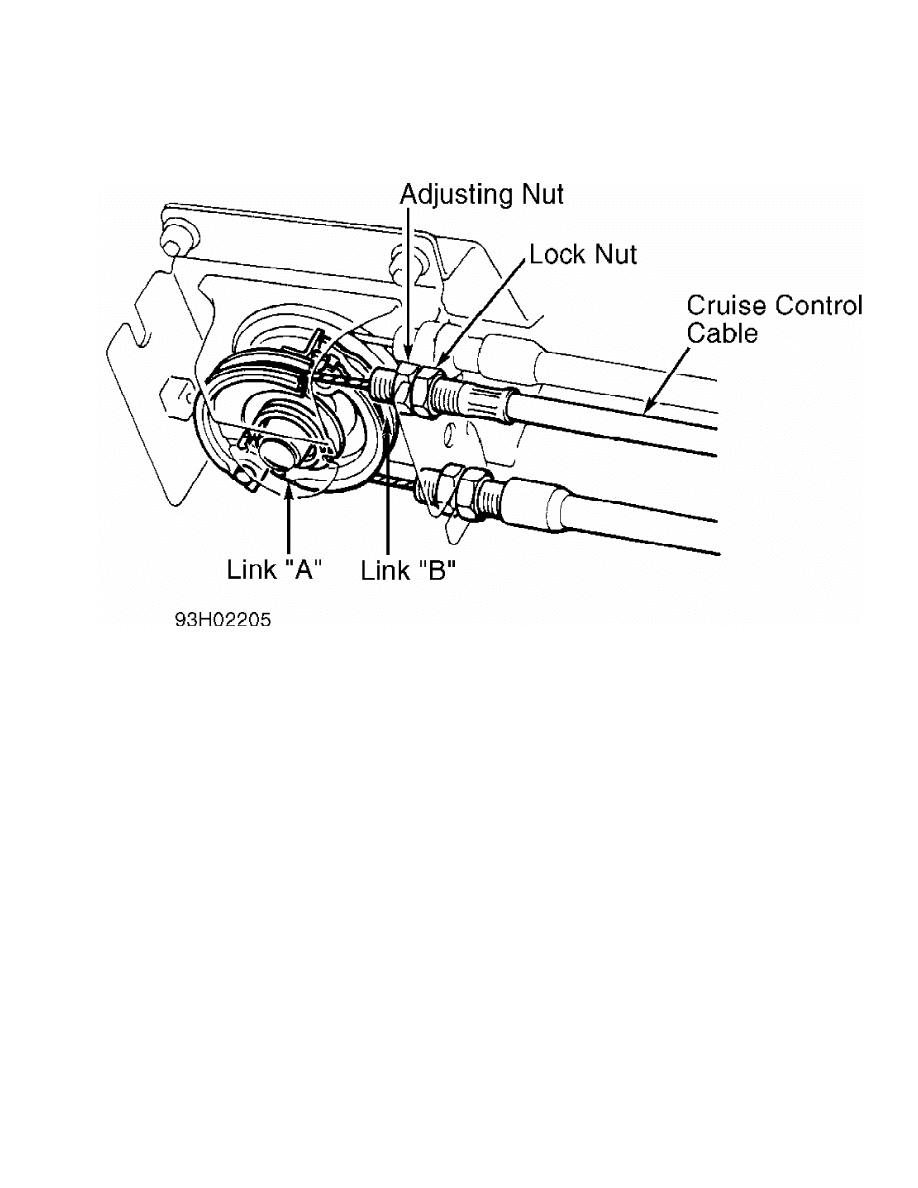
Fig. 1: Adjusting Cruise Control Cable
Courtesy of Mitsubishi Motor Sales of America
DIAGNOSIS & TESTING
CRUISE CONTROL SWITCH FUNCTION TEST
NOTE: If vehicle speed decreases approximately 9 MPH below set
speed, set speed will be canceled.
1) Cruise control switch is part of multifunction switch
mounted on steering column. To operate cruise control system, turn
ignition on. Turn cruise control switch to ON position. Ensure switch
indicator light comes on.
NOTE: Speed will not set beyond system limit of 90 MPH.
2) With cruise control switch in ON position, drive vehicle
between 25 and 90 MPH. Press and release SET button. Vehicle speed
should stay at set speed. Instrument cluster cruise indicator light
should come on. To increase set speed, turn control switch to RESUME
position and hold until new set speed is reached.
3) To lower set speed, press SET button and hold until new
set speed is reached. To return to set speed after cancellation, move
resume switch from ON to OFF position. Vehicle speed should return to
previous setting before cancellation. Set speed should cancel when any
of the following occurs:
* Brake pedal is pressed.
* Clutch pedal is pressed.
* Transmission is shifted to Neutral or Park.
* Cruise control main switch is turned to OFF position.
* Ignition switch is turned to OFF position.
SELF-DIAGNOSTICS
1) Self-diagnostics should be performed when cruise control
cancels without the driver using normal cancel modes. Diagnosis
connector is located on right side of fuse box. Use analog voltmeter
or Scan Tester (MB991341) for code retrieval.
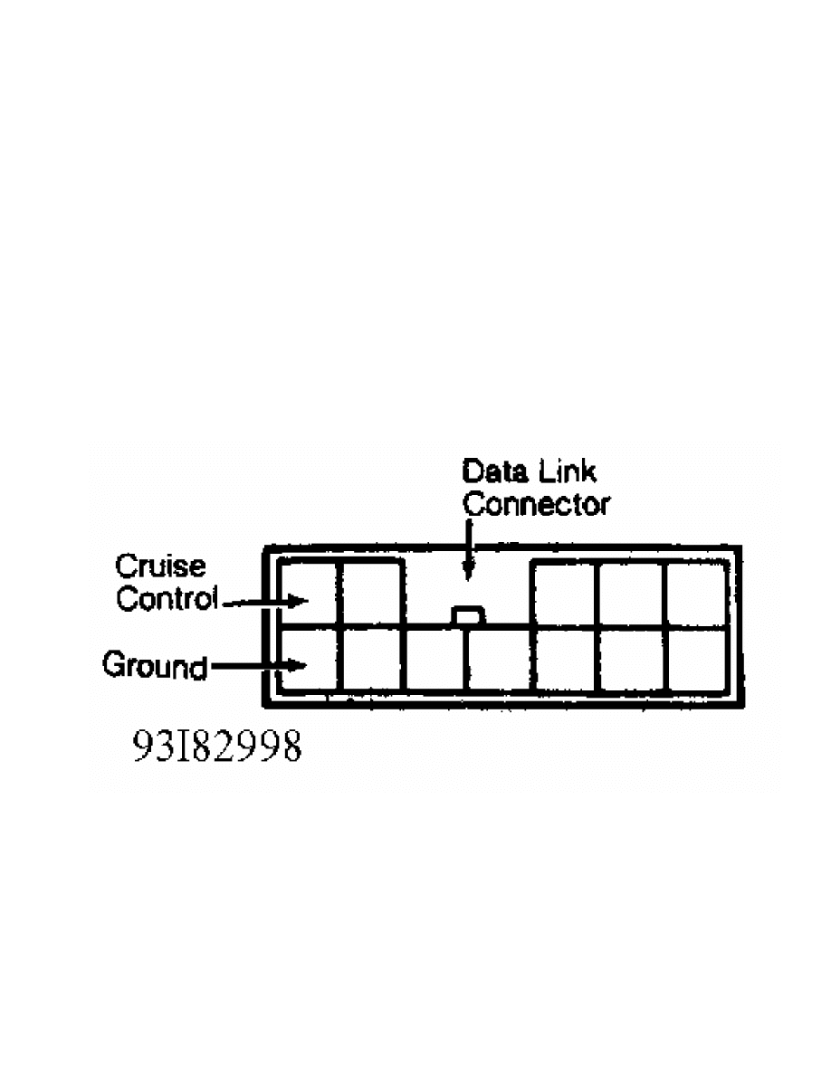
2) Use scan tester according to operating instructions
provided with tester. Connect leads of analog voltmeter between cruise
control terminal and ground terminal of data link connector. See
Fig. 2. Read voltmeter needle sweeps to determine trouble code.
3) Once trouble codes have been displayed, see SELF-
DIAGNOSTIC CODE CHART to determine appropriate CIRCUIT TEST. See
Fig. 3.
4) To clear trouble codes, either disconnect battery cable or
turn ignition on. Turn main cruise control switch and set switch to ON
position. Within one second turn resume switch to ON position.
5) Hold stoplight switch and cruise control switch in ON
position for more than 5 seconds. Verify codes are cleared.
Fig. 2: Data Link Connector Terminal ID
Courtesy of Mitsubishi Motor Sales of America
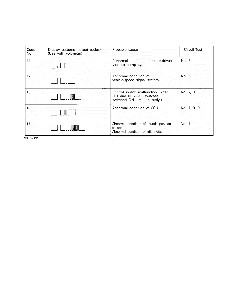
Fig. 3: Self-Diagnostic Code Chart
Courtesy of Mitsubishi Motor Sales of America
SYSTEM INPUT TESTS
1) System input tests should be performed if no trouble codes
are stored when performing SELF-DIAGNOSTICS. System input tests cycle
each cruise control switch and sensor.
2) Use Scan Tester (MB991341) for system input check. Use
scan tester according to operating instructions provided with tester.
Connect leads of analog voltmeter between cruise control terminal and
ground terminal of data link connector. See Fig. 2. Turn ignition
switch to ON position. Follow INPUT CODE CHART sequence. See Fig. 4.
3) To display results of input check, move SET switch to ON
position. Then turn MAIN switch to ON position. Within one second,
activate RESUME switch. Codes will display if circuit tested is okay.
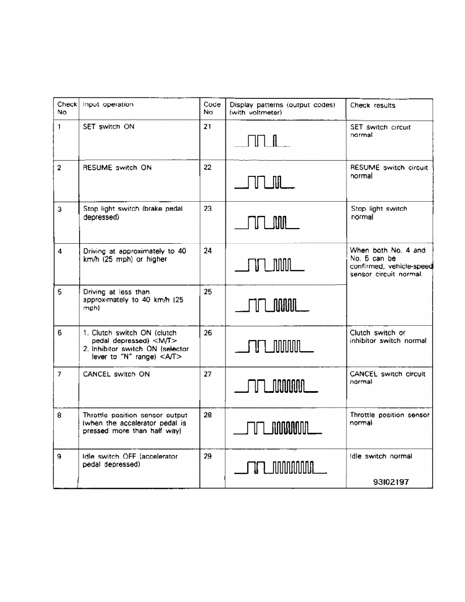
Fig. 4: Input Code Chart
Courtesy of Mitsubishi Motor Sales of America
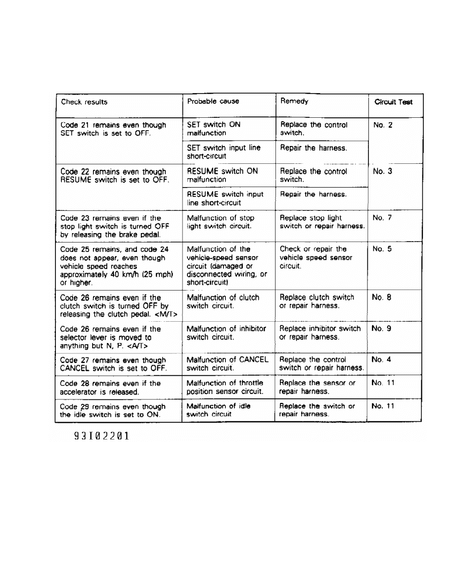
Fig. 5: Check Results Chart
Courtesy of Mitsubishi Motor Sales of America
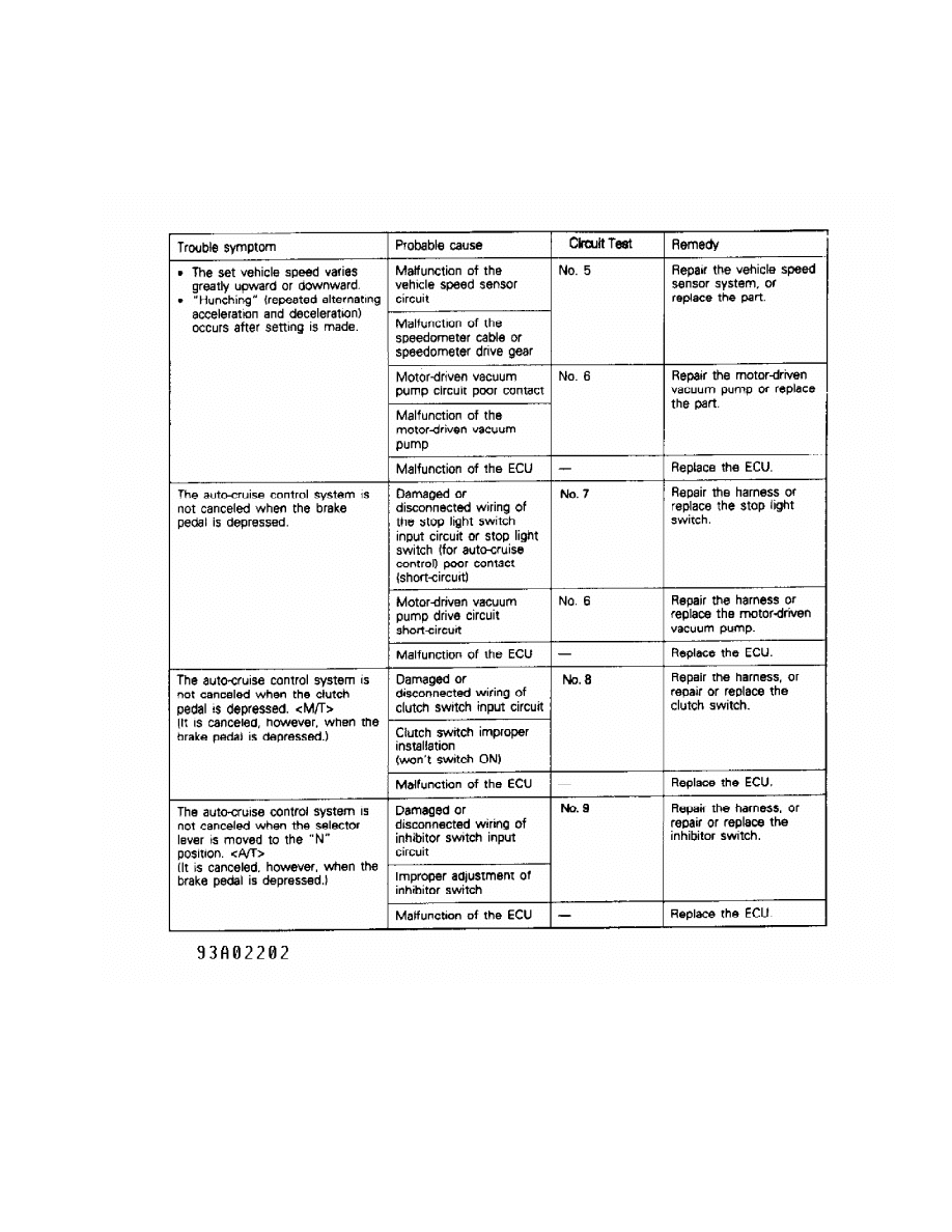
Fig. 6: Symptom Chart (1 Of 2)
Courtesy of Mitsubishi Motor Sales of America
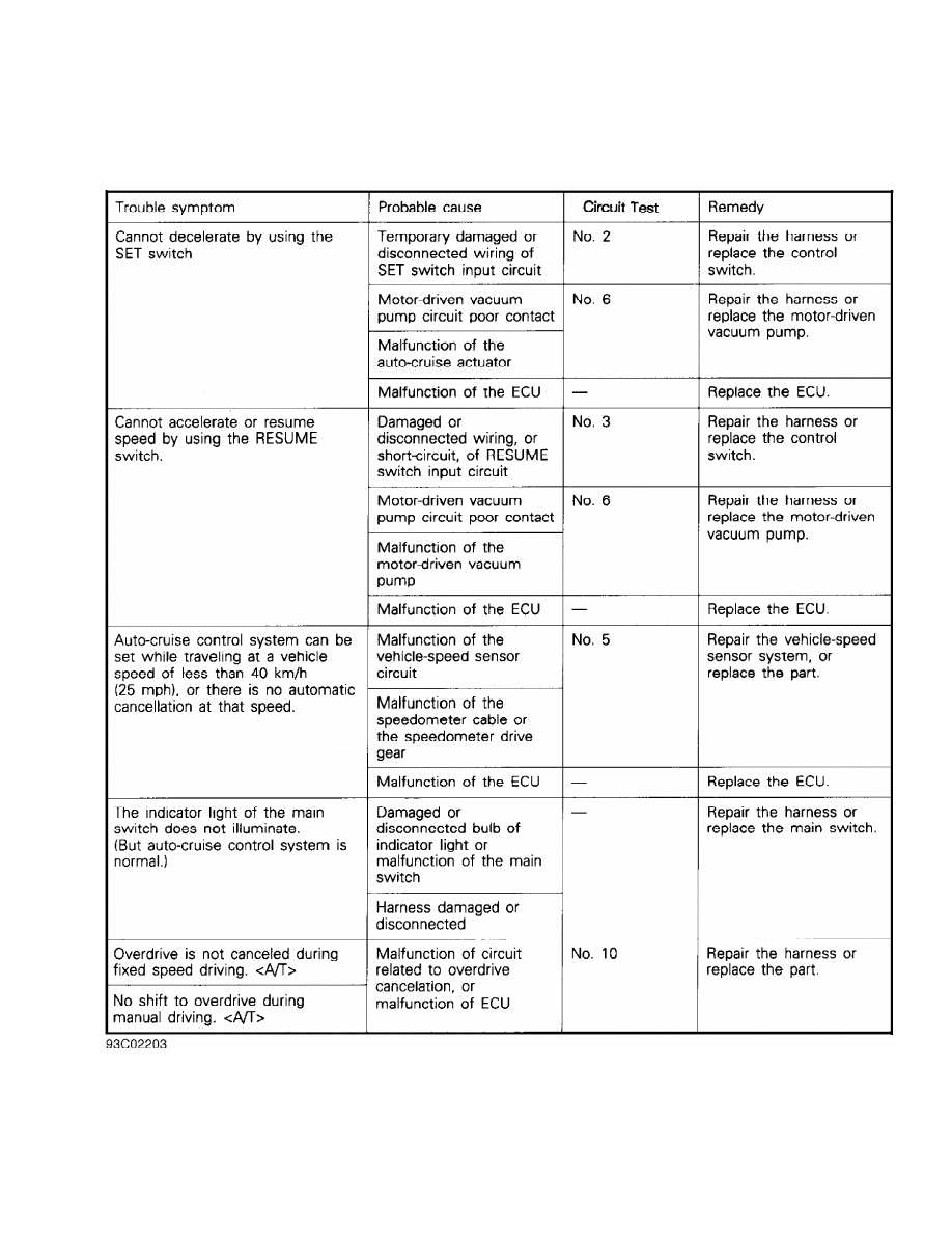
Fig. 7: Symptom Chart (2 Of 2)
Courtesy of Mitsubishi Motor Sales of America
CIRCUIT TESTS
NOTE: To identify circuit connector terminals, see Figs. 8-15. See
appropriate wiring diagram in the WIRING DIAGRAMS section.

Test No. 1 (Power & Ground Circuit)
1) Turn ignition on. When cruise control main switch is
turned to ON position, battery voltage should be present on terminal
No. 2 of cruise control unit connector.
2) If voltage is not present, check fuse No. 11 and replace
as necessary. If fuse is okay, check and repair harness as necessary.
Terminal No. 8 should be grounded at all times. If terminal No. 8 is
not grounded, repair harness.
Test No. 2 (Set Switch Circuits)
When set switch is turned to ON position, 3 volts should be
present on terminal No. 18 of cruise control unit. When set switch is
turned to OFF position, voltage should not be present on terminal No.
18 of cruise control unit. If circuit does not test correctly, replace
switch as necessary or repair harness.
Test No. 3 (Resume Switch Circuit)
When resume switch is turned to ON position, 6 volts should
be present on terminal No. 18 of cruise control unit. When resume
switch is turned to OFF position, voltage should not be present on
terminal No. 18 of cruise control unit. If circuit does not test
correctly, replace switch as necessary or repair harness.
Test No. 4 (Cancel Switch Circuit)
When cancel switch is turned to On position, battery voltage
should be present on terminal No. 18 of cruise control unit. When
cancel switch is in OFF position, voltage should not be present on
terminal No. 18 of cruise control unit. If circuit does not test
correctly, replace switch as necessary or repair harness.
Test No. 5 (Vehicle Speed Sensor Circuit)
When vehicle moves slowly, voltage should alternate between
zero and 2 or more volts at terminal No. 19 of cruise control unit. If
circuit does not test correctly, replace sensor as necessary or repair
harness.
Test No. 6 (Vacuum Pump Circuit)
1) When cruise system is in deceleration or release mode,
battery voltage should be present on terminals No. 26 and 13 of cruise
control unit. If circuit does not test correctly, replace vacuum pump
as necessary or repair harness.
2) When cruise system is in release mode, battery voltage
should be present on terminal No. 12 of cruise control unit. When
cruise system is in hold mode, voltage on terminals No. 12, 13 and 26
will go from battery voltage to zero volts depending on driving
conditions. If circuit does not test correctly, replace vacuum pump as
necessary or repair harness.
Test No. 7 (Stoplight Switch Circuit)
When brake pedal is pressed, battery voltage should be
present on terminal No. 15 of cruise control unit. If voltage is not
present, adjust or replace brake switch. If circuit does not test
correctly, replace switch as necessary or repair harness.
Test No. 8 (Clutch Switch Circuit)
When clutch pedal is pressed, battery voltage should be
present at terminal No. 1 of cruise control unit. If circuit does not
test correctly, replace switch as necessary or repair harness.
Test No. 9 (Inhibitor Switch Circuit)
When transmission is in Neutral position, battery voltage
should be present on terminal No. 1 of cruise control unit. If circuit
does not test correctly, replace switch as necessary or repair
harness.
Test No. 10 (Overdrive Switch Circuit)
When overdrive switch is pushed to ON position, battery
voltage should be present on terminal No. 11 of cruise control unit.
If circuit does not test correctly, replace switch as necessary or
repair harness.
Test No. 11 (Idle Switch & Throttle Position Sensor Circuit)
1) When accelerator pedal is pressed, 4.5-5.5 volts should be
present on terminal No. 4 (idle switch) of cruise control unit. When
accelerator pedal is released, voltage should not be present on
terminal No. 4 of cruise control unit.
2) When accelerator pedal is pressed to wide open throttle,
4.0-5.5 volts should be present on terminal No. 5 (throttle position
sensor) of cruise control unit. When accelerator pedal is released, .
5-.7 volt should be present on terminal No. 5 of cruise control unit.
If circuit does not test correctly, replace sensor as necessary or
repair harness.
CRUISE CONTROL CONNECTOR ID
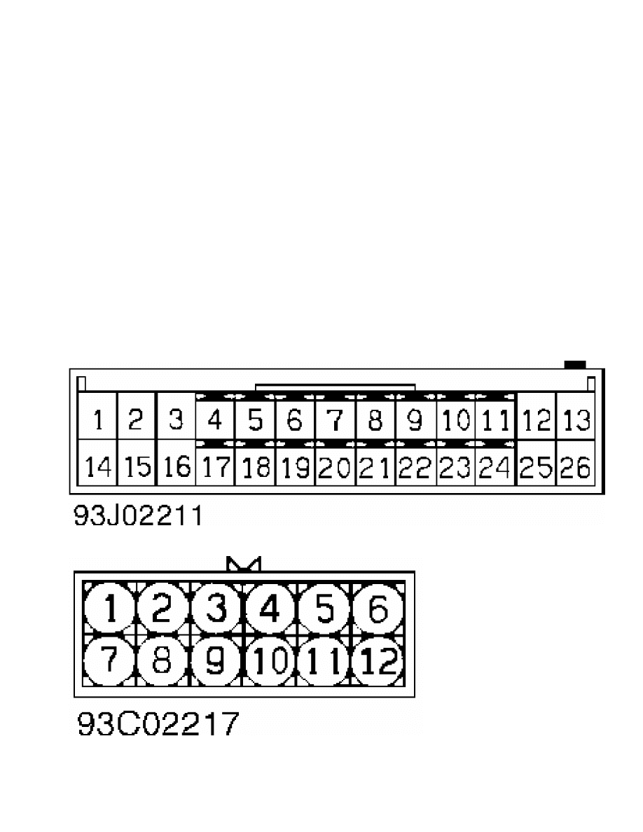
Fig. 8: Cruise Control Unit Connector Terminal ID
Courtesy of Mitsubishi Motor Sales of America.
Fig. 9: Main Cruise Control Switch Connector Terminal ID
Courtesy of Mitsubishi Motor Sales of America.
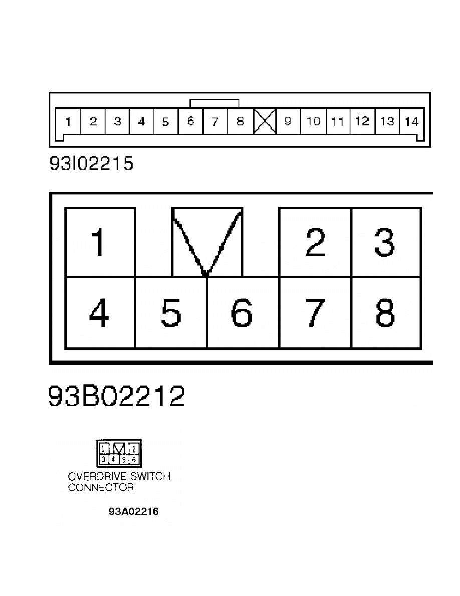
Fig. 10: Stoplight Switch Connector Terminal ID
Courtesy of Mitsubishi Motor Sales of America.
Fig. 11: Vacuum Pump Connector Terminal ID
Courtesy of Mitsubishi Motor Sales of America.
Fig. 12: Instrument Cluster Connector Terminal ID
Courtesy of Mitsubishi Motor Sales of America.
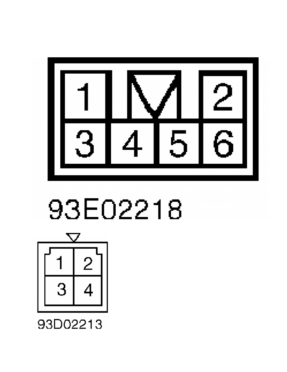
Fig. 13: Overdrive Switch Connector Terminal ID
Courtesy of Mitsubishi Motor Sales of America.
Fig. 14: Inhibitor Switch Connector Terminal ID
Courtesy of Mitsubishi Motor Sales of America.

Fig. 15: Throttle Position Sensor & Idle Switch Connector Terminal ID
Courtesy of Mitsubishi Motor Sales of America.
CRUISE CONTROL SWITCH TESTS

Set & Resume Switches
1) Remove lower steering column cover. Disconnect 2-pin
switch connector. Operate and test switch. When cancel switch is
operated, continuity should be present between terminals No. 1 and 2.
Zero ohms resistance should be indicated.
2) When resume switch is operated, 820 ohms resistance should
be present between terminals No. 1 and 2. When set switch is operated,
2700 ohms resistance should be present between terminals No. 1 and 2.
Replace cruise control switch if it does not test correctly.
Main Switch
1) In each switch position, continuity should be present
between terminals No. 2 and 7 for switch illumination. See Fig. 9.
When switch is moved to Neutral position, continuity should be present
between terminals No. 1 and 4.
2) When switch is moved to ON position, continuity should be
present between terminals No. 1, 4 and 5. Connect battery voltage to
terminal No. 5 and ground terminal No. 4.
3) Battery voltage should be present on terminal No. 1 when
main switch is moved to ON position. Replace switch if it does not
test correctly.
BRAKELIGHT/STOPLIGHT SWITCH TEST
Disconnect switch connector. When brake pedal is pressed,
continuity should be present between terminals No. 2 and 3. See
Fig. 10. When brake pedal is released, continuity should be present
between terminals No. 1 and 4. Replace switch if it does not test
correctly.
IDLE SWITCH & THROTTLE POSITION SENSOR TESTS
Throttle Position Sensor
1) Disconnect sensor connector. Resistance between terminals
No. 1 and 4 should be 3500-6500 ohms. Use an analog ohmmeter to
measure resistance between terminals No. 1 and 3. See Fig. 15.
2) Slowly open throttle valve to wide open throttle.
Resistance should change smoothly as throttle is opened. Replace
throttle position sensor if it does not test correctly.
Idle Switch
1) Disconnect throttle position sensor connector. Continuity
should be present between terminals No. 1 and 2 with accelerator pedal
released. See Fig. 15. Continuity should not be present with
accelerator pedal pressed.
2) If continuity is not present with accelerator released,
loosen throttle position sensor mounting screw. Turn throttle position
sensor completely clockwise. Recheck continuity. Replace throttle
position sensor if idle switch does not test correctly.
INHIBITOR SWITCH TEST
Disconnect switch connector. Shift transaxle into Neutral and
Park positions. Continuity should be present between terminals No. 7
and 12. See Fig. 14. If continuity is not present, adjust inhibitor
switch. If switch is adjusted properly, replace switch.
VACUUM PUMP TEST
1) Remove vacuum pump connector. Resistance should be 50-60
ohms between terminal No. 1 and terminals No. 2 and 3. See Fig. 11.
Ensure solenoid valve makes operating noise when battery voltage is
applied between terminal No. 1 and terminals No. 2 and 3.
2) If solenoid valve does not make noise, replace vacuum pump
assembly. Apply battery voltage to terminals No. 1 and 4, motor should
operate. Replace vacuum pump if motor does not operate.
ACTUATOR TESTS
Remove actuator. Apply vacuum to actuator. Actuator linkage
holder should move more than 1.38" (35 mm). Actuator diaphragm should
hold vacuum. Replace actuator if actuator does not test correctly.
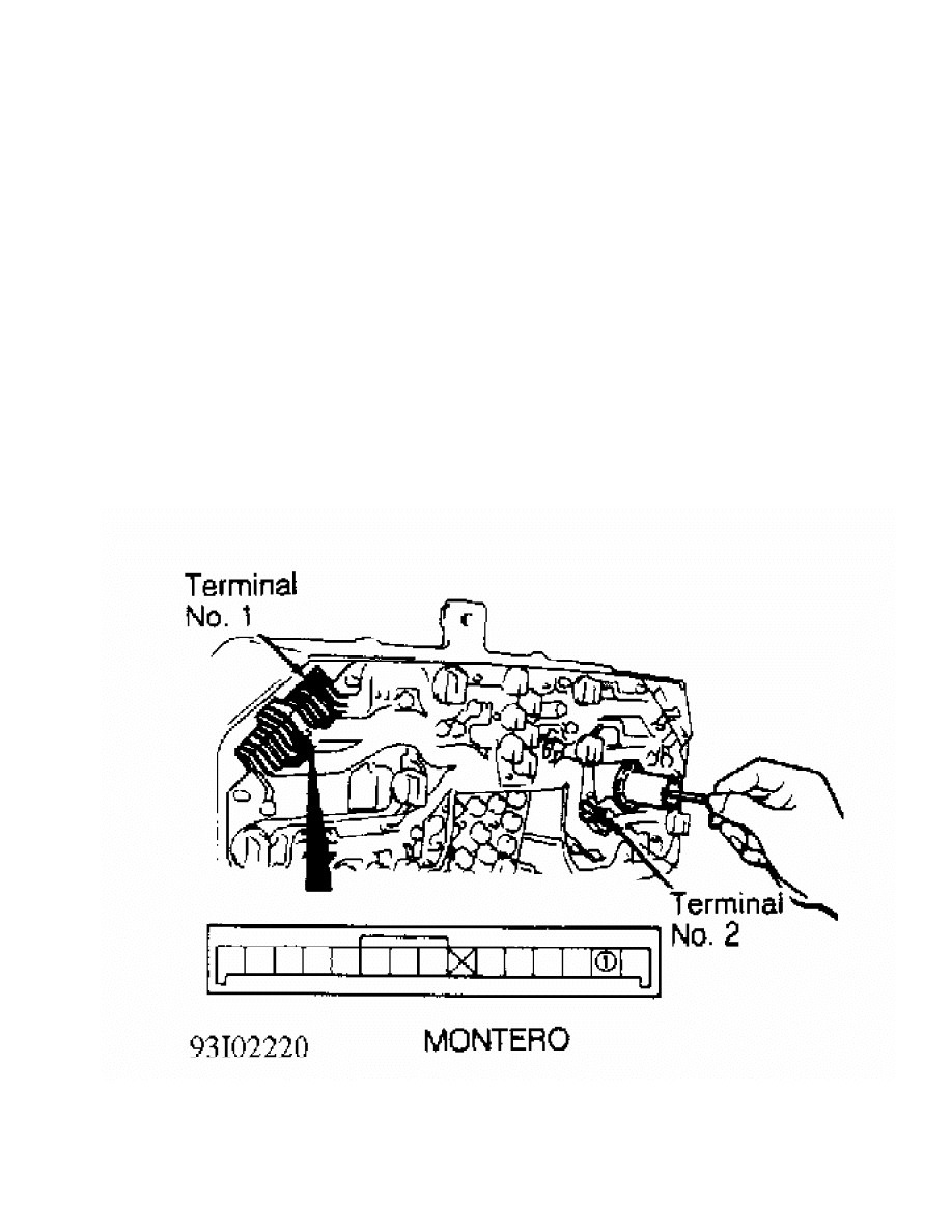
VEHICLE SPEED SENSOR TEST
1) Remove instrument cluster. See INSTRUMENT CLUSTER under
REMOVAL & INSTALLATION. Check continuity between vehicle speed sensor
terminals at instrument cluster. See Fig. 16.
2) Ensure continuity pulses on and off 4 times per revolution
of speedometer shaft connection. If continuity is not as specified,
replace vehicle speed sensor.
Fig. 16: Checking Speed Sensor Circuit
Courtesy of Mitsubishi Motor Sales of America
REMOVAL & INSTALLATION

ACTUATOR
Removal & Installation
Disconnect cruise control cable from link. Disconnect
actuator wiring connector. Remove vacuum pump and vacuum pump bracket.
Remove actuator and actuator bracket. To install, reverse removal
procedure.
CRUISE CONTROL SWITCH
Removal & Installation
Remove lower steering column cover. Disconnect electrical
connectors. Remove screws attaching cruise control switch to steering
column. Remove switch. To install, reverse removal procedure.
VEHICLE SPEED SENSOR
Removal & Installation
Remove instrument cluster. See INSTRUMENT CLUSTER. Speed
sensor is a part of speedometer.
INSTRUMENT CLUSTER
Removal & Installation
Disconnect negative battery cable. Remove cluster cover.
Disconnect speedometer cable. Remove instrument cluster. To install,
reverse removal procedure.
CONTROL UNIT
Removal & Installation
Cruise control unit is located behind center of dash panel.
Remove center trim panel and radio or radio plug bezel. Remove control
unit. To install, reverse removal procedure.
WIRING DIAGRAMS
See appropriate chassis wiring diagram in the WIRING DIAGRAMS
section.
Wyszukiwarka
Podobne podstrony:
32 Audi A6 Cruise control system petrol engines
04 6 F01 Cruise Control Systems
Control System Toolbox
10 Emission control system
07 emission control system
10 Engine Control System
Cruise Control I4
ENGINE CONTROL SYSTEM
10 Engine Control System
Core Wall Survey Control System for High Rise Buildings
Air Control System
80 Vehicle Control System
Microprocessor Control System for PWM IGBT Inverter Feeding Three Phase Induction Motor
Control Systems Simulation using Matlab and Simulink
opis Control System XControl XC XV
autronic instrukcja obslugi programowalnego ukladu sterujacego lambda control system al700
80 Vehicle Control System
82 Cruise Control
więcej podobnych podstron