
Initial Print Date: 10/06
Table of Contents
Subject
Page
Rear-view Camera . . . . . . . . . . . . . . . . . . . . . . . . . . . . . . . . . . . . . . . . . . . . . .3
Input/Output . . . . . . . . . . . . . . . . . . . . . . . . . . . . . . . . . . . . . . . . . . . . . . . . . . .4
Rear-view Camera System Schematic . . . . . . . . . . . . . . . . . . . . . . . . . . . .5
Rear-view Camera System with Video Module Schematic . . . . . . . . . . .6
K-CAN Signals at Rear-view Camera Control Unit . . . . . . . . . . . . . . . . . .8
Basic Functions of the Rear-view Camera System . . . . . . . . . . . . . . . . . .9
Image Reproduction Functions . . . . . . . . . . . . . . . . . . . . . . . . . . . . . . . . . . .9
Lens Coverage Alignment . . . . . . . . . . . . . . . . . . . . . . . . . . . . . . . . . . . . . .10
Electronic Image Equalization . . . . . . . . . . . . . . . . . . . . . . . . . . . . . . . . . . .10
View of Image Section . . . . . . . . . . . . . . . . . . . . . . . . . . . . . . . . . . . . . . . . .11
Virtual Camera Pan . . . . . . . . . . . . . . . . . . . . . . . . . . . . . . . . . . . . . . . . . . . .11
Camera Pan as a Function of Speed . . . . . . . . . . . . . . . . . . . . . . . . . . . . .12
Additional Functions of the Rear-view Camera System . . . . . . . . . . . . .12
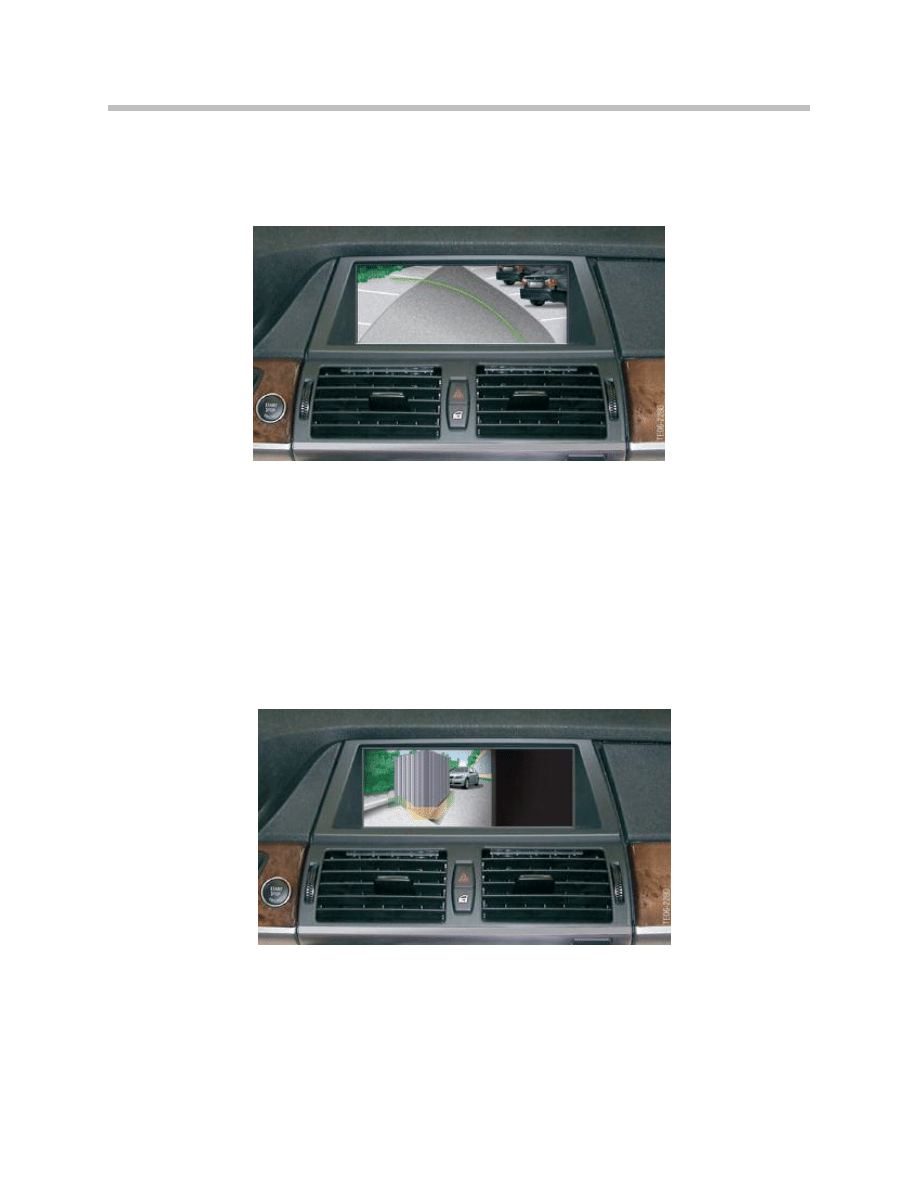
Assistance Graphics in Camera Image . . . . . . . . . . . . . . . . . . . . . . . . .12
Lane Help Lines . . . . . . . . . . . . . . . . . . . . . . . . . . . . . . . . . . . . . . . . . . . .13
Turning Circle Lines . . . . . . . . . . . . . . . . . . . . . . . . . . . . . . . . . . . . . . . . .13
Obstacle Markings . . . . . . . . . . . . . . . . . . . . . . . . . . . . . . . . . . . . . . . . . .14
Zoom of Towing Hitch . . . . . . . . . . . . . . . . . . . . . . . . . . . . . . . . . . . . . . .15
Personal Profile . . . . . . . . . . . . . . . . . . . . . . . . . . . . . . . . . . . . . . . . . . . . .15
Automatic System Activation . . . . . . . . . . . . . . . . . . . . . . . . . . . . . . . . .16
Location or Rear-view Camera . . . . . . . . . . . . . . . . . . . . . . . . . . . . . . . .18
Calibration of the Rear-view Camera . . . . . . . . . . . . . . . . . . . . . . . . . . . . .19
E70 Rear-view Camera (RFK)
Revision Date:

2
E70 Rear-view Camera
Rear-view Camera
Model: E70
Production: From Start of Production
After completion of this module you will be able to:
• Describe the functions of the E70 Rear-view camera.
• Diagnose and Service components and functions of the
E70 Rear-view camera.
Rear-view Camera
The Rear-view camera system (RFK) serves to assist the driver when driving into/out
of parking spaces and maneuvering.
As well as showing a high-quality wide-angle image of the area behind the vehicle, the
system contains a series of additional customer functions.
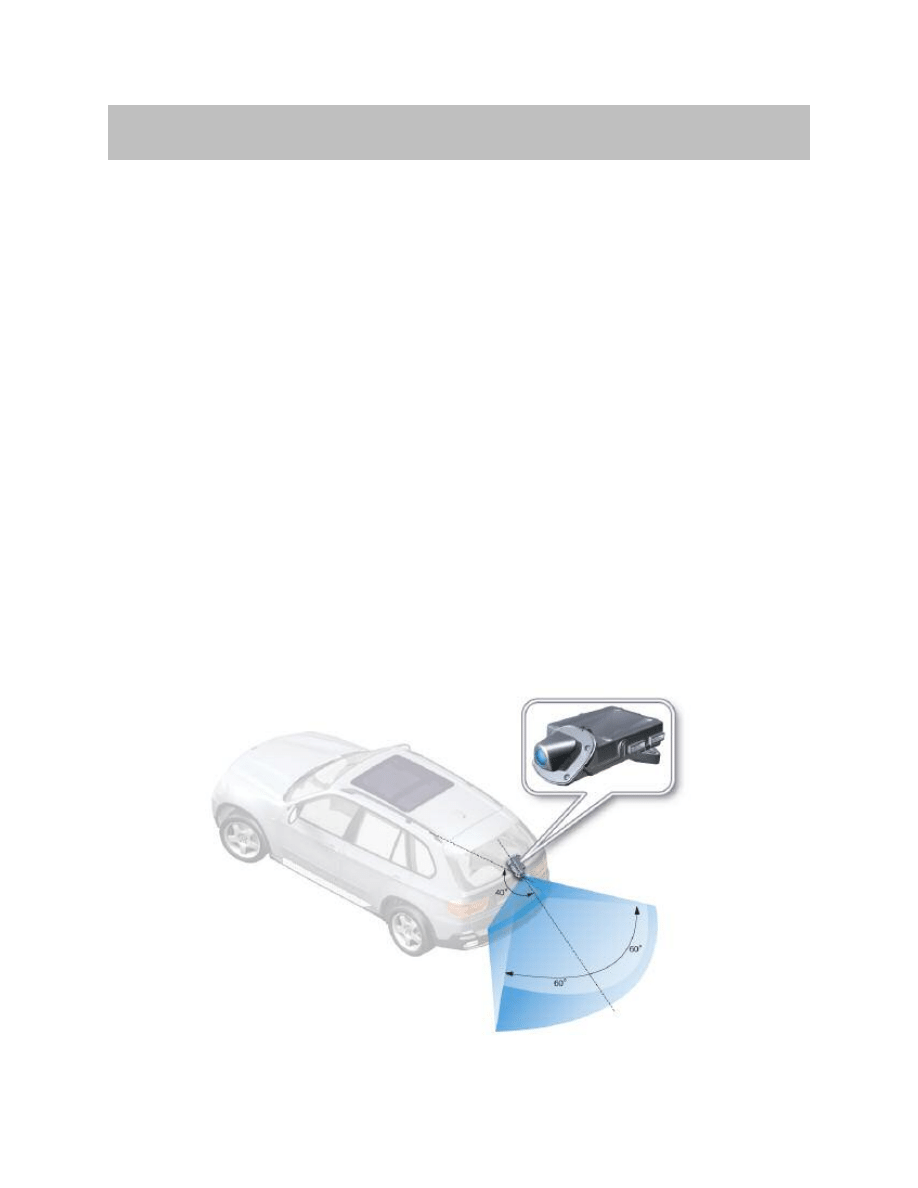
The system is located in the tailgate. The Rear-view camera is located offset to the right
of vehicle center in the tailgate strip handle.
The Rear-view camera is activated automatically together with the park distance control
by engaging reverse gear or manually by pressing the parking button. A wide angle color
image of the area behind the vehicle is shown on the central screen. The electronic
equalizer ensures natural perspectives in the image. Driver assistance graphics in the
image show the calculated space requirement for parking into spaces and maneuvering
referred to the current steering wheel position thus assisting the driver when parking into
spaces. The shaded obstacle markings in the real camera image that are based on the
ultrasonic sensor system help the driver (in addition to the PDC warning tone) to pay par-
ticular attention to obstacles and confined areas when parking into spaces and maneu-
vering. Selection menus on the central information display allow for interactive changes
to the system settings. Automatic activation of the system can also be disabled in these
menus. Following activation after opening the vehicle, the rear-view camera is not avail-
able before the navigation display is operational.
3
E70 Rear-view Camera
Introduction
Range of Rear-view Camera
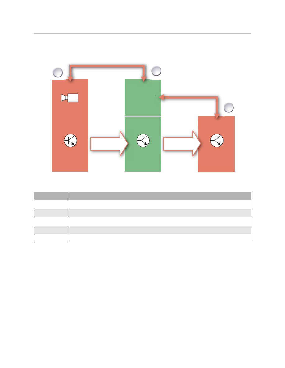
The rear-view camera is controlled by means of the K-CAN and MOST bus systems
while the CCC acts as the gateway. The video signal is transmitted via a separate video
link (CVBS, RGB) to the car communication computer. From there, the existing LVDS
connection is used.
RFK
CID
CCC
Gateway
K-CAN
K-CAN
1
3
2
4
E70 Rear-view Camera
Input/Output
Index
Explanation
1
Rear-view camera system
2
Car communication computer
3
Central information display
K-CAN
Body CAN
MOST
Media Oriented System Transport

5
E70 Rear-view Camera
NOTES
PAGE
6
E70 Rear-view Camera
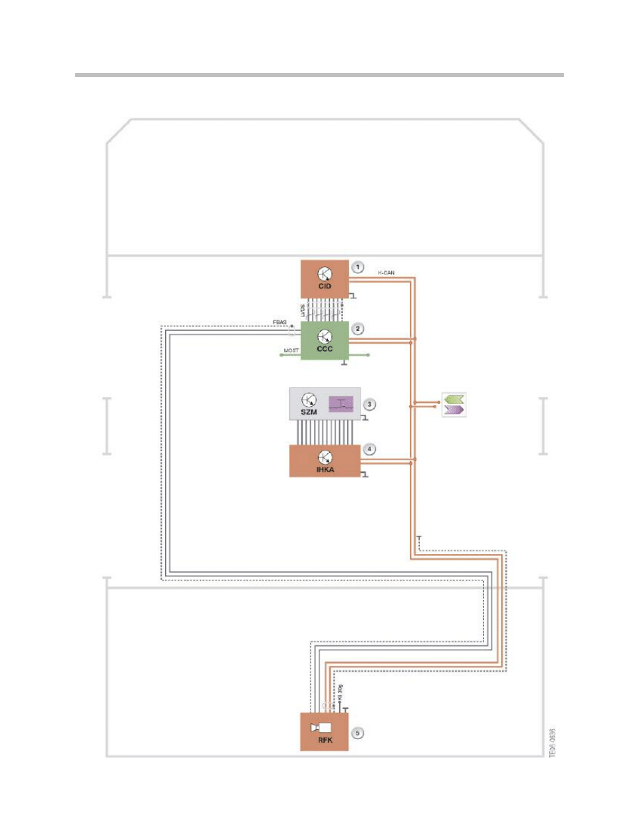
Rear-view Camera System Schematic

Legend for Rear-view Camera System Schematic
7
E70 Rear-view Camera
Index
Explanation
1
Central information display
2
Car communication computer
3
Center console switch cluster
4
Automatic climate control
5
Rear-view camera
6
Video module
K-CAN
Body CAN
LVDS
LVDS data line
FBAS
CVBS line
MOST
Media Oriented System Transport
KL 30g
Terminal 30g

K-CAN Signals at Rear-view Camera Control Unit
8
E70 Rear-view Camera
In/Out
Signal
Source
Function
In
PDC signals
PDC sensors
PDC control unit
Information for superimposing
distance graphics
In
PDC button
PDC button in center console
Air conditioning control unit
Activation and deactivation of
the Rear-view camera system
In
Road speed
Wheel speed sensors
DSC control unit
Deactivation of Rear-view cam-
era system from a speed of 20
km/h in forward driving
Differentiation, forward
driving/reversing
In
Configuration
Controller
Head unit (Champ/CCC)
Configuration of displays and
functions of Rear-view camera
system
In
Steering wheel angle
Steering angle sensor
Steering column switch cluster
Adaptation of lane help lines to
the steer angle
In
Vehicle inclination
Ride-height sensor
Footwell module/VDM
Adaptation of lane help lines to
vehicle inclination
In
Outside temperature
Outside temperature sensor
instrument cluster
Defrosting of rear-view camera
lens
In
Distance travelled
Wheel-speed sensors
DSC control unit
Rear-view camera system
switches off display after a dis-
tance of 50 m in forward
direction
In
Tailgate
Contact, tailgate
CAS control unit
No lane help lines are superim-
posed when the tailgate is open
Out
CC messages
Head unit (Champ/CCC)
> CID control unit
CC messages are forwarded to
the existing head unit
Basic Functions of the Rear-view Camera System
The basic function of the rear-view camera system is to record optically a wide-angle
view (about 120°) of the area behind the vehicle. The image is recorded via the lens in
the rear-view camera system and then transmitted in electronically conditioned form to
the car communication computer (CCC).
The video picture is transmitted via a video interface (CVBS, RGB). Communication for
controlling the system in the entire vehicle and connection to the overall-bus system are
effected via a K-CAN interface.
In addition, the rear-view camera system serves to show further assorted assistance
information in the form of superimposed overlays (graphics and text) in the output signal
(superimposed with the real camera picture).
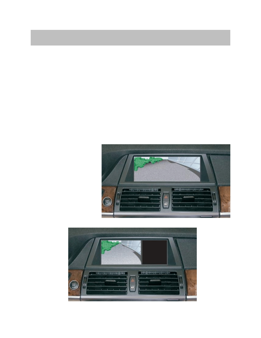
Image Reproduction Functions
The rear-view camera system
shows the view of the area
behind the vehicle with a hori-
zontal aperture angle of 120°
on the central information dis-
play. The view can be shown
on the navigation display in
two modes:
9
E70 Rear-view Camera
Functions
Full image view 620x240 pixels
Main window view 400x240 pixels
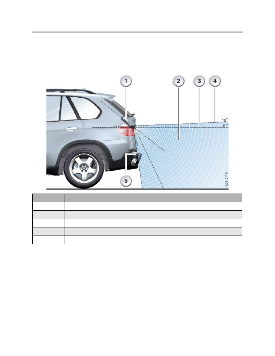
Lens Coverage Alignment
The entire coverage area of the rear-view camera system ranges from the bumper at the
bottom up to an angle of 10° from the horizontal at the top.
Electronic Image Equalization
The rear-view camera features an electronic image equalizer. The equalizer serves the
purpose of correcting the distortions in vertical and horizontal correction caused by the
principle of the wide-angle lens. The equalization algorithm must be such that the sec-
ondary effects such as information loss in the form of blurred edges as well as distortion
that occurs as part of the equalization process are minimized.
The aim is to achieve the most realistic representation of the view of the area behind the
vehicle that can be unmistakably interpreted by the driver
10
E70 Rear-view Camera
Index
Explanation
1
Rear-view camera system
2
Coverage range
3
Horizontal
4
Maximum possible upward coverage range (10° upward from the horizontal)
5
Rear bumper
View of Image Section
The Rear-view camera system always provides a view of a certain section of the overall
image. This makes it possible to adapt to the external conditions of the vehicle. If the vehi-
cle is parked on uneven ground so that it is not straight, the Rear-view camera system
can adapt the video image corresponding to the incoming information.
This function is required for realizing the functions described in the following:
• Virtual camera pan
• Image adaptation to vehicle inclination
• Software-based system calibration
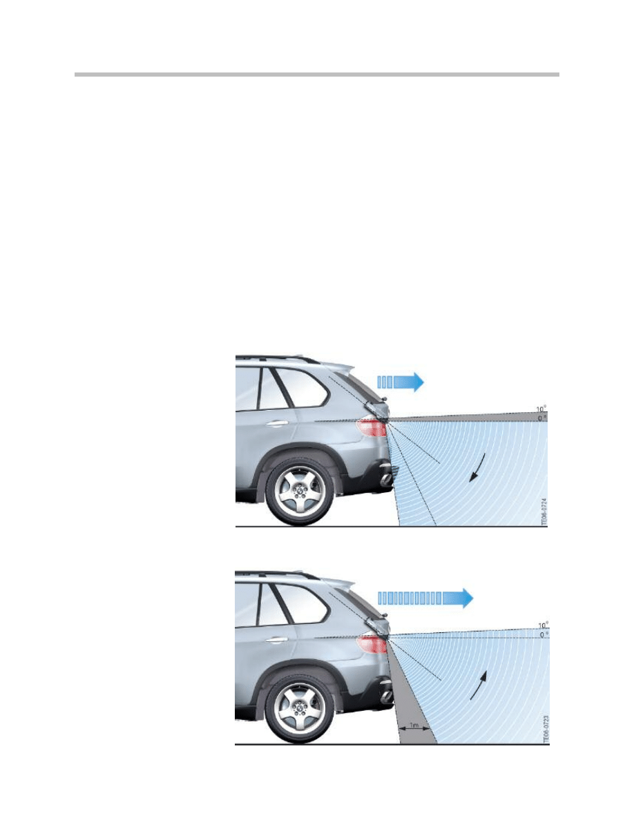
Virtual Camera Pan
Different areas are shown on the screen in vertical direction depending on the driving
speed.
The bottom area of the
image (from the bumper up
to the horizontal) is shown
when rear-view at slow
speed (up to about 3mph)
Increasingly only the upper
area of the image (from
about 1m distance from the
vehicle up to a minimum
angle of 10° above the hori-
zontal) is shown on the
screen when rear-view at
faster speed (more than 3
mph)
11
E70 Rear-view Camera
Camera Pan as a Function of Speed
The camera pans virtually without the camera moving mechanically. This function gives
the driver a view of the area behind the vehicle adapted to the current speed. When dri-
ving at slow speed, the area very close to the rear of the vehicle is shown so that every
detail can be recognized. At speeds above 3 mph, the upper section of the image is
shown to provide an extended view.
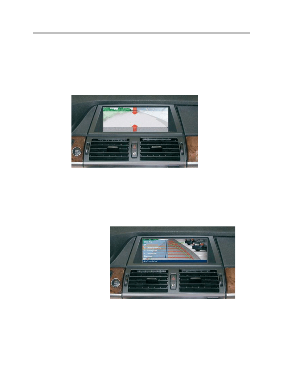
Additional Functions of the Rear-view Camera System
Assistance Graphics in Camera Image
Assistance graphics are superimposed on the camera image to help the driver to park
into spaces and maneuver.
The following assistance graphics can be superimposed:
• Lane help lines
• Turning circle lines
• Obstacle markings
• Zoom of towing hitch
Note: The brightness can be adjusted or the image completely switched off
12
E70 Rear-view Camera
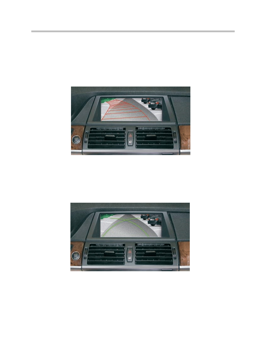
Lane Help Lines
The lane help lines are used to show the predicted path of the vehicle and therefore the
required maneuvering space depending on the current position of the steering wheel.
The lane help lines are deactivated automatically when driving in forward direction.
Turning Circle Lines
The turning circle lines mark the minimum possible vehicle turning circle. These marks
remain superimposed on the image also when driving in forward direction.
13
E70 Rear-view Camera
Only the relevant turning circle line is shown as soon as the driver turns the steering
wheel. The opposite turning circle line is blanked out depending on the steering lock and
is no longer shown at full lock.
Obstacle Markings
Obstacle markings shown in the real camera image are partly transparent overlays true to
scale of the obstacle detected by the PDC. The obstacle distribution in the area behind
the vehicle is shown as a 3D graphic. Its form, position and color depend on the distance
to each of the four PDC sensors in the bumper. Through corresponding visualization with
form and color, the way the obstacle markings are represented gives the driver a spatial
perspective of the obstacle distribution about the area behind the vehicle. The view corre-
sponds to the virtual PDC view.
14
E70 Rear-view Camera

Personal Profile
The settings last made by each user are stored in the Rear-view camera system and
retrieved after corresponding identification. The following setting options can be stored in
the rear-view camera depending on the vehicle key.
• Display format (full image, main window as well as permanently switch on/off camera
image)
• Lane help lines (ON/OFF)
• Turning circle lines (ON/OFF)
• Obstacle markings (ON/OFF)
• Camera pan (ON/OFF)
• Image brightness (brightness value)
15
E70 Rear-view Camera

System Activation
System activation by driver The Rear-view camera system can be activated by the driver
by pressing the parking aid button (PDC button) as from terminal 15. The system can no
longer be activated at a speed higher than 12 mph
Automatic System Activation
Initially, the Rear-view camera system is ready to send data after engaging reverse gear
(identification by CAN messages) and then sends an enquiry to the CCC. In response,
the CCC gives the authorization to output the video signal. The rear-view camera video
signal is output only after receiving this authorization.
A corresponding error message is sent in the form of a CC message in the event of the
Rear-view camera system not being available.
System Deactivation
Automatic or Indirect System Activation.
The rear-view camera is deactivated automatically in response to the following conditions:
• After exceeding a certain preset speed Vmax - forward (about 12mph) as well as
• A preset distance (about 50m) when driving in forward direction.
Deactivation by Vehicle User
Deactivation by vehicle user (while image from the rear-view camera is shown on the
CID) by:
• Operating iDrive (pop-up menu)
• Pressing the PDC button
The rear-view camera is activated again when reverse gear is engaged.
Permanent System Deactivation
The rear-view camera can be permanently deactivated in the 5th menu.
16
E70 Rear-view Camera
Rear-view Camera Design
The rear-view camera is based on a CMOS sensor (Complementary Metal Oxide
Semiconductor sensor) adapted for use in the vehicle with an integrated image process-
ing unit for full-digital processing of the raw sensor data (up to 110 Mbits/s). The electron-
ic circuitry is designed as a two-processor system. The image processing takes place in
the electronic module. The following processing steps are executed:
• Histogram control - brightness and color adaptation to various exposure scenarios
• Image equalization - compensation of lens effects
• Superimposition of driver assistance line and camera pan
• Calibration functions
The tasks of bus communication, flash and boot routines and other standard applications
are implemented in a separate microprocessor.
The lens with the 2.0 shutter is made up of 6 glass lenses.
It contains an automatically controlled heating element to de-ice the lens in winter. The
heating element is largely controlled infinitely variable with a PWM control.
17
E70 Rear-view Camera
Index
Explanation
1
Processor for bus communication, flash and boot routines
2
Processor for all image conditioning functions
3
CMOS image sensor
4
Heater
5
Lens
6
Power supply and bus link connector
7
Signal output connector
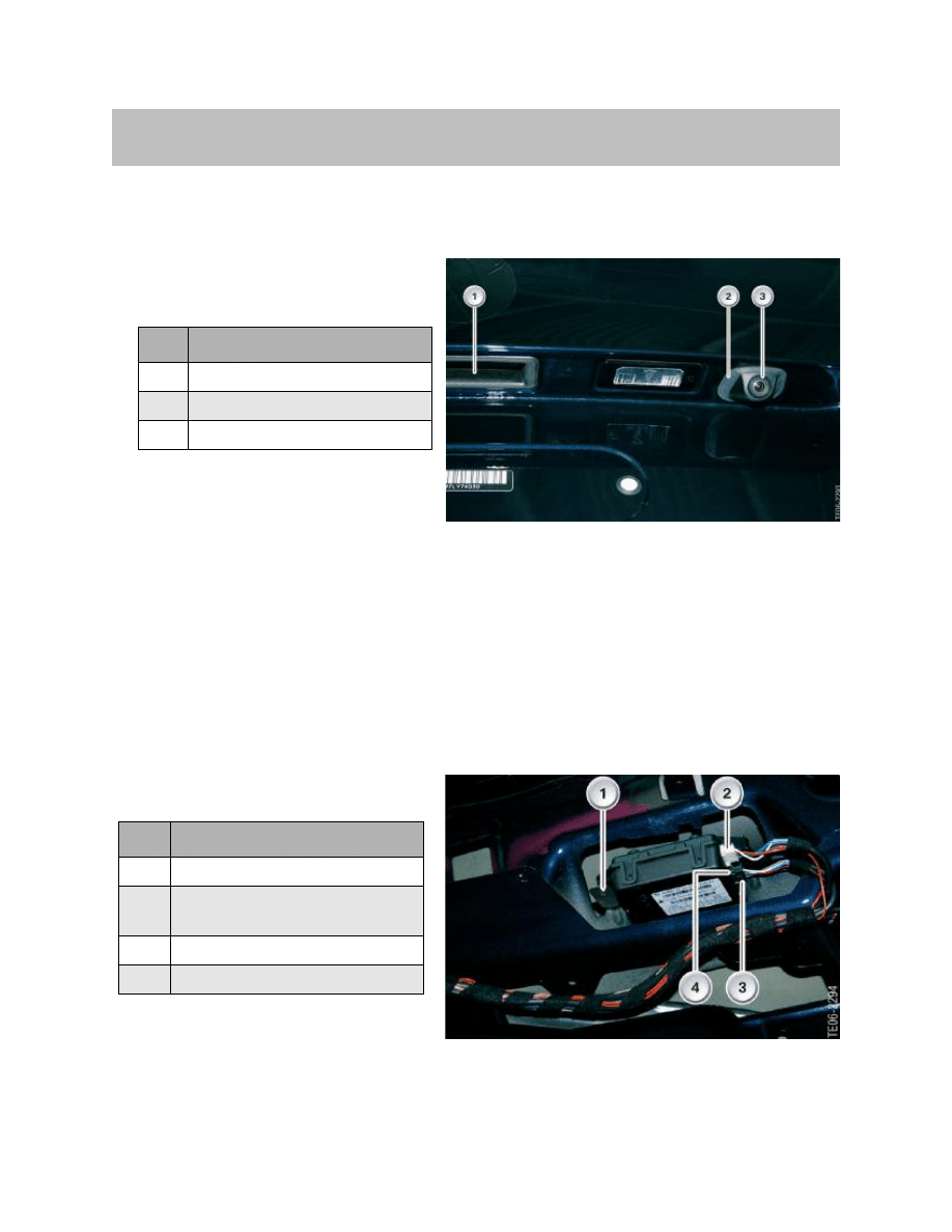
The Rear-view camera system is installed on the right in the tailgate next to the tailgate
lock. Tailgate seal A rubber seal seals off the housing of the rear-view camera from the
tailgate.
Mounting in the Tailgate
The rear-view camera is installed from the rear of the tailgate and secured to the housing
by means of two screws.
Temperature-controlled Lens Thawing
In freezing conditions, the camera lens is heated and thawed automatically to keep it free
of snow and ice.
Location or Rear-view Camera
18
E70 Rear-view Camera
Index
Explanation
1
Tailgate handle
2
Rear-view camera seal
3
Rear-view camera lens
Index
Explanation
1
Mounting screw
2
Connector, white (power supply
and bus connection)
3
Mounting screw
4
Connector, black (video signal)

Calibration of the Rear-view Camera
Note: In order to maintain the accuracy of the rear-view camera, a calibration
procedure must followed as per the latest BMW Service information
found in TIS or on the GT-1.
19
E70 Rear-view Camera
Service Information
Document Outline
- Main Menu
- E70 Introduction
- E70 Glovebox
- E70 Powertrain
- E70 Gasoline Engines
- E70 Transmissions
- E70 Voltage Supply and Bus Systems
- E70 Car Access System 3
- E70 Energy Management
- E70 Chassis Dynamics
- E70 Lateral Dynamics Systems
- E70 Vertical Dynamics Systems
- E70 Longitudinal Dynamics Systems
- E70 Central Locking
- E70 Power Windows
- E70 Comfort Access
- E70 Wipe/Wash System
- E70 Panorama Glass Sunroof
- E70 Seats
- E70 Automatic Tailgate
- E70 Steering Column Switch Cluster
- E70 Exterior Lighting
- E70 Interior Lighting
- E70 Adaptive Headlight System
- E70 Park Distance Control
- E70 Rear-view Camera
- E70 Anti-Theft Alarm System
- E70 Outside Mirrors
- E70 Displays Indicators and Controls
- E70 Head-up Display
- E70 Information and Communication
- E70 Audio Systems
- E70 Rear Seat Entertainment
- E70 Climate Control Systems
- E70 Passive Safety Systems
Wyszukiwarka
Podobne podstrony:
07c E70 Rear Seat Entertainment
05 11 F01 Exterior Rear View Mirrors
HONDA Ridgeline Rear Camera System Owner's Manual
ACURA RL Rear Camera System Owner s Manual
mapi com The Ayurvedic View of Marijuana
M32d Rear Suspension
BMW X5 E70 2007pl
18 Series Tandem Pump Exploded View
Dirkon camera obscura do składania
e rachunkowosc pl artykul php view=920
Instrukcja obsługi Nokia Fun Camera PL
pinhole camera
Exploded view
18 Series Variable Pump Exploded View
27 Rear Suspension
M34e Rear Drum Brakes
kombi siedzenie naprawa stuck rear seat 01 wagon removing installing pull cable rear backrest
ARTICLE BRAKES PAD REAR SERVICE
więcej podobnych podstron