
OFFICIAL WARWICK
AMP OWNER MANUAL
ENGLISH
TAKE 12
SAFETY HINTS
- Read these instructions
- Keep these instructions
- Heed all warnings
- Follow these instructions
Caution: To reduce the risk of electrical shock, do
not remove the cover. Or expose this appliance to
rain or moisture. No user serviceable parts inside;
refer serving to qualified personnel.
Apparatus shall not be exposed to dripping or
splashing and no objects filled with liquids, such
as vases shall be placed on the apparatus.
This symbol, wherever it appears, alerts you to
the presence of uninsulated dangerous voltage
inside the enclosure--voltage that may be suffi-
cient to constitute risk of shock.
This symbol, wherever it appears, alerts you to
important operating and maintenance instructi-
ons in the accompanying literature. Read the
manual.
Use only with cart, stand, tripod, bracket or table
specified by the manufacture, or cart/apparatus
combination to avoid injury from tip-over.
!

3
RECOMMENDATIONS
The following recommendations are designed to ensure that the device always functions reliably:
• Never open the casing! To do so would expose you to the risk of an electric shock. Should repairs prove necessary, leave
them to qualified service personnel.
• Avoid dust and high moisture levels, direct sunlight and extremely high or low temperature.
• Safeguard the device from excessive vibration. Always place the unit on a stable and horizontal surface.
• See to adequate ventilation. The device should not be placed on soft surfaces (carpet, cushions, etc.). When mounting
it in a rack, make sure that the rear and lateral cooling vents remain unobstructed.
• Avoid leaving the unit near radiators or other objects producing heat.
• Internal components should only be adjusted or cleaned by qualified service technicians. Ensure no object or liquid
penetrates the device through its cooling vents.
• When replacing a fuse make sure you fit in one of identical value!
Have the device examined by a qualified service technician in the following cases:
• the mains lead or mains switch have been damaged,
• objects or liquids have penetrated the device,
• it has been exposed to excessive moisture,
• malfunctions or abnormal operating conditions have occurred,
• the device has been dropped or the casing damaged.
Congratulations on the purchase of the new Warwick combo. Please read through these instructions
before connecting and operating the device. If you keep to the guidelines set out in this manual, you will
soon be able to appreciate the quality of this new Warwick amplifier. Please keep this instruction boo-
klet handy in case you need to consult it again. Please send the PASSPORT to the address indicated the-
rein.
HINTS
- This apparatus shall not be exposed dripping or splashing and that no objects filled with liquids, such as vases, shall
be placed on the apparatus.
- This apparatus should be connected to a MAINS socket outlet with a protective earthing connection.
- Mains plug or appliance connector shall be used as the disconnect device, so mains plug or appliance connector should
always remain readily operable.
- If the apparatus shows any malfunction, immediately disconnect the main power cord from the mains socket.
- Do only operate effects pedals in-between the instrument and the amplifier, as these devices are not designed for the
supplied load of an effects loop.
- Remove the plug whenever changing a fuse.
- Only ever replace a fuse with another of the same type. Never bridge defective fuses.
- Make sure the top and bottom of the device are properly ventilated and that the vents are not blocked.
- Do not subject the device to excessive vibration or hard jolts as these could damage the device.
- Don't undertake repairs yourself.
- Only allow the case to be opened by qualified personnel. (Remove the plug).
- Repairs should only be undertaken by qualified personnel.
SHOULD YOU FIND YOURSELF ONE DAY WONDERING: "WHY IS THERE NO SOUND COMING OUT?"
please check:
- all stub cables,
- all connections of these cables
and proceed anew by following the guidelines of the chapter GETTING STARTED. Possibly the problem reveals to be an
operational error.

4
PROTECTIVE CIRCUITS
Your new Warwick amplifier is equipped with a series of circuits to prevent it from destruction in case of inadequate ope-
rating conditions:
Power-up delay:
When the unit is switched on, the SPEAKER OUT sockets are activated with a slight delay to
protect the loudspeakers.
Short-circuit:
In the event of a short-circuit at the power amp outputs, this feature prevents the output stage
transistors from destruction by quickly reducing current.
Direct current (DC): This circuit continuously monitors the power amp output for direct current and protects the loud
speakers from overload should a transistor burn out.
HF oscillation:
By switching the power amp off, this safety feature prevents from damages that could be caused
by frequencies in excess of 20 kHz (feedback, etc.).
Excessive
temperatures:
Should the temperature-regulated fan cooler prove to be insufficient in extreme conditions, this
circuit protects the output stage transistors from destruction by switching the device off.
Limiter:
The combos CL and CCL are equipped with a limiter, that limits the poweramp outputs to
200 watts (CL), 300 watts (CCL) in order to protect the loudspeakers.
Note:
You can recognise that one of these circuits has been activated as a result of a fault, when the
MUTE LED glows continuously even though you have not selected the MUTE mode. In case of
a short-circuit please check the speaker cable. The amplifier must then be switched off and on
again, to get back into playing mode after having removed the short-circuit. In any other situation
the amplifier switches automatically back to playing mode as soon as it detects the fault has
disappeared (e.g. the amplifier has overheated and cooled down again).
GETTING STARTED
1.
Make sure that loudspeakers capable of sustaining the load of a bass signal are connected to the SPEAKER OUT
sockets, resp. the speaker unit should be linked to the SPEAKER OUT at the combos.
2.
Check that the mains supply has been plugged in and that all external (effects) units possibly used are correctly con-
nected and operational.
3.
Set the MASTER control to zero.
4.
Plug your bass guitar into the amplifier's INPUT with a shielded line-cable.
5. Press
the
POWER switch to turn the device on.
6. Switch
MUTE off and the red LED will extinguish.
7. Switch
the
LIMITER off (the 2-colored LED will extinguish, CL, CCL).
8. Turn all volume controls of your bass guitar on to their maximum.
9.
Adjust the GAIN control until the (loudly) played bass signal flashes the clip LED.
10. Set the MASTER control to the volume you wish to play at.
11. Adjust the sound that you wish with the controls and switches described in the respective chapters FRONT PANEL
CONTROLS.
12. If necessary readjust GAIN.
13. Should you seek for a peak limited sound, activate the LIMITER (LED green) and fix its threshold (LED shifts to red)
with GAIN.
5
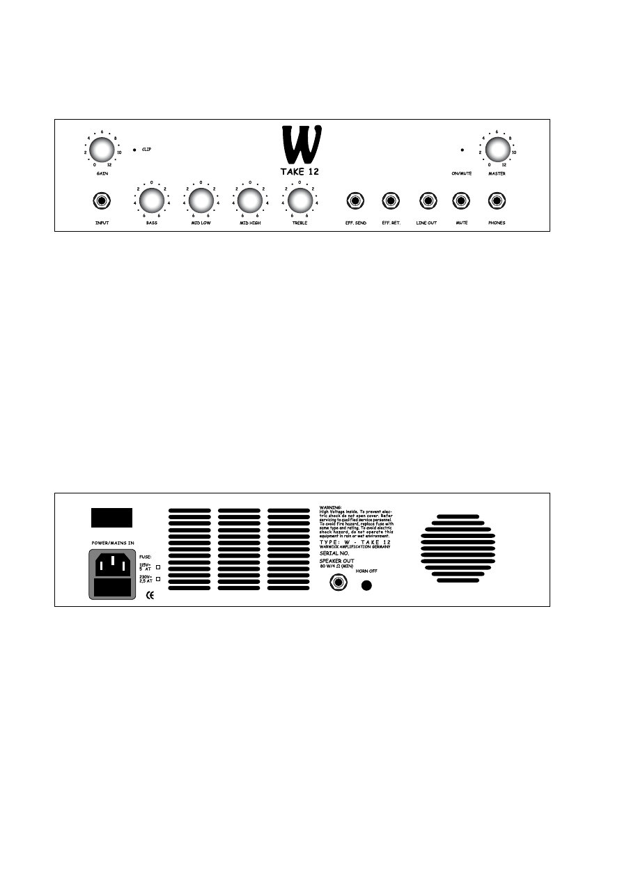
FRONT PANEL CONTROLS
INPUT
socket to plug in a bass guitar.
GAIN
control + CLIP LED to adjust the input level.
BASS
control to boost/cut deep frequencies.
MID LOW
control to boost/cut low mids
MID HIGH
control to boost/cut high mids
TREBLE
control to boost/cut high frequencies.
EFF. LOOP
for the insertion of effects units. Connect SEND with the input and RETURN with the output of the
effects device.
LINE OUT
socket allows to connect additional power amplifiers or active cabinets.
MASTER
control determines the mains level.
MUTE
switch + ON/MUTE LED cuts the signal from all outputs, except from the PHONES socket
PHONES
socket for connecting a headphone (min 200 Ω).
REAR PANEL
MAINS IN AC
Terminal with integrated fuse compartment for connecting the amplifier to the current network.
POWER
switch for turning the amplifier on and off.
SPEAKER OUT
socket for connecting the loudspeaker.
HORN OFF
switch to switch off the hf horn.

6
TECHNICAL DATA
Take 12
Sweet 15
CL
CCL
SUB III
Input
25 mV
25 mV
25 mV
25 mV
25 mV
Preamp CH 1
transistor
active controlled
transistor
active controlled
transistor
active controlled
transistor
active controlled
none
Preamp CH 2
n/a
n/a
n/a
n/a
n/a
Poweramp
fan cooled
(non permanent)
fan cooled
(non permanent)
fan cooled
(non permanent)
fan cooled
(non permanent)
fan cooled
(non permanent)
CH 1 Equalizer
bass, mid low, mid high,
treble controls
bass. mid low, mid high,
treble controls, low
boost/high boost swit-
ches
bass, param.mids with
freq, and level controls,
treble, low boost, high
boost switches, Dyn.
control with switchable
limiter
bass, punch, param. mids
with freq. and level con-
trols, attack, treble, low
boost and high boost
switches. Dyn. control
with switchable limiter
CH 2 Equalizer
n/a
n/a
n/a
n/a
n/a
Headphone
min 200 Ω
min 200 Ω
min 200 Ω
min 200 Ω
none
Direct Out
none
none
0 dB, 600 Ω
0 dB, 600 Ω
none
Effects Loops
mono serial
send 0 dBu, 600 Ω
return 0 dBu, 10 kΩ
mono serial
send 0 dBu, 600 Ω
return 0 dBu, 10 kΩ
mono serial
send 0 dBu, 600 Ω
return 0 dBu, 10 kΩ
mono serial
send 0 dBu, 600 Ω
return 0 dBu, 10 kΩ
none
Switches
Horn Off
Horn Off
ground lift.
DI pre/post
ground lift, DI pre/post
-3 dB pad
Rear Control
none
none
Horn Attennator
Horn Attennator
none
Footswitch Jack
n/a
n/a
n/a
n/a
n/a
Nominal Power
80W / 4Ω jack
150W / 4Ω jack
200W / 4Ω jack
300W / 4Ω jack
300W
THD
<0.1%
<0.1%
<0.1%
<0.1%
<0.1%
Weight (kg)
16.5
25
20
27.75
24.2
Dimensions (mm)
395 x 555 x 325
530 x 640 x 340
441 x 396 x 460
531 x 484 x 600
440 x 480 x 600
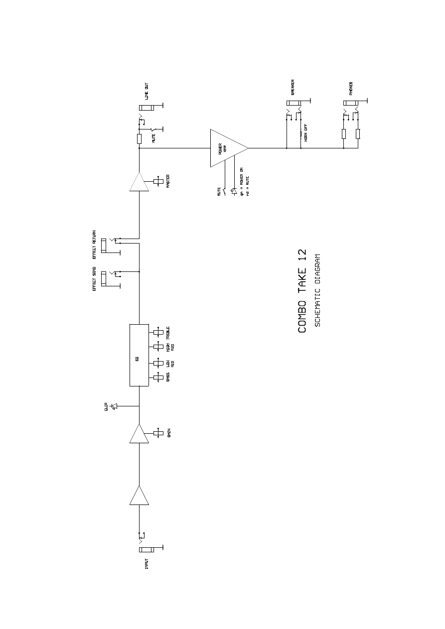
7
CIRCUIT DIAGRAM

Headquarters:
Warwick GmbH&Co.Music Equipment KG • Gewerbegebiet Wohlhausen • 08258 Markneukirchen/Germany • E-Mail: info@warwick.de
Branch China:
Warwick Music Equipment (Shanghai) Ltd., Co.•Shanghai Waigaoqiao Free Trade Zone • Shanghai 200131/P.R.China • E-Mail: info@warwick.cn
Branch UK:
Warwick Music Equipment Trading (Manchester UK) Ltd. • 75 Bridge Street • Manchester M3 2RH / Great Britain • E-Mail: info@warwickbass.co.uk
Branch Switzerland:
Warwick Music Equipment Trading (Zurich) GmbH • Kriesbachstrasse 30 • 8600 Dübendorf / Switzerland • E-Mail: info@warwick.ch
Branch CZ:
Warwick Music Equipment Trading (Praha CZ) s.r.o. • Spálená 23/93 • 11000 Praha 1 / Czech Republik • E-Mail: info@warwick.cz
Visit us on the World Wide Web: http://www.warwick.de
Wyszukiwarka
Podobne podstrony:
Budzik Versa wielkość karty kredytowej instrukcja EN
G2 4 PW EN wn Rys 01
Manual Acer TravelMate 2430 US EN
Ćwiczenie 01 EN DI
eci en
BVSOI 3 001 E en
A Biegus projektowanie konctrukcji stalowych wg PN EN 1993 1 1 cz 1
Flavon Active dopping EN
5817 PN EN ISO IV 2007
Pisownia ę ą en em om
NS2 lab 4 4 7 en Configure Cisco IOS IPSec using Pre Shared Keys
PN EN 1990 2004 AC Podstawy projektowania konstrukcji poprawka
EN w9 wspolpraca z siecia
EN SUPERRAIL
overview simatic controllers 04 2007 en plc
1510478 8000SRM0988 (06 2005) UK EN
HGDS EN
więcej podobnych podstron