
Chapter 12:
EQUILIBRIUM AND ELASTICITY
1. A net torque applied to a rigid object always tends to produce:
A. linear acceleration
B. rotational equilibrium
C. angular acceleration
D. rotational inertia
E. none of these
ans: C
2. The conditions that the net force and the net torque both vanish:
A. hold for every rigid body in equilibrium
B. hold only for elastic solid bodies in equilibrium
C. hold for every solid body
D. are always sufficient to calculate the forces on a solid object in equilibrium
E. are sufficient to calculate the forces on a solid object in equilibrium only if the object is
elastic
ans: A
3. For an object in equilibrium the net torque acting on it vanishes only if each torque is calculated
about:
A. the center of mass
B. the center of gravity
C. the geometrical center
D. the point of application of the force
E. the same point
ans: E
4. For a body to be in equilibrium under the combined action of several forces:
A. all the forces must be applied at the same point
B. all of the forces form pairs of equal and opposite forces
C. the sum of the components of all the forces in any direction must equal zero
D. any two of these forces must be balanced by a third force
E. the lines of action of all the forces must pass through the center of gravity of the body
ans: C
5. For a body to be in equilibrium under the combined action of several forces:
A. all the forces must be applied at the same point
B. all of the forces form pairs of equal and opposite forces
C. any two of these forces must be balanced by a third force
D. the sum of the torques about any point must equal zero
E. the lines of action of all the forces must pass through the center of gravity of the body
ans: D
176
Chapter 12:
EQUILIBRIUM AND ELASTICITY

6. To determine if a rigid body is in equilibrium the vector sum of the gravitational forces acting
on the particles of the body can be replaced by a single force acting at:
A. the center of mass
B. the geometrical center
C. the center of gravity
D. a point on the boundary
E. none of the above
ans: C
7. The center of gravity coincides with the center of mass:
A. always
B. never
C. if the center of mass is at the geometrical center of the body
D. if the acceleration due to gravity is uniform over the body
E. if the body has a uniform distribution of mass
ans: D
8. The location of which of the following points within an object might depend on the orientation
of the object?
A. Its center of mass
B. Its center of gravity
C. Its geometrical center
D. Its center of momentum
E. None of the above
ans: B
9. A cylinder placed so it can roll on a horizontal table top, with its center of gravity above its
geometrical center, is:
A. in stable equilibrium
B. in unstable equilibrium
C. in neutral equilibrium
D. not in equilibrium
E. none of the above
ans: B
10. A cylinder placed so it can roll on a horizontal table top, with its center of gravity below its
geometrical center, is:
A. in stable equilibrium
B. in unstable equilibrium
C. in neutral equilibrium
D. not in equilibrium
E. none of the above
ans: A
Chapter 12:
EQUILIBRIUM AND ELASTICITY
177
11. A cube balanced with one edge in contact with a table top and with its center of gravity directly
above the edge is in
equilibrium with respect to rotation about the edge and in
equilibrium with respect to rotation about a horizontal axis that is perpendicular to the edge.
A. stable, stable
B. stable, unstable
C. unstable, stable
D. unstable, unstable
E. unstable, neutral
ans: C
12. A meter stick on a horizontal frictionless table top is pivoted at the 80-cm mark. A force F
1
is applied perpendicularly to the end of the stick at 0 cm, as shown. A second force F
2
(not
shown) is applied perpendicularly at the 100-cm end of the stick. The forces are horizontal. If
the stick does not move, the force exerted by the pivot on the stick:
0 cm
20 cm 40 cm 60 cm 80 cm
•
100 cm
......
......
......
......
......
......
......
......
......
......
......
......
.............
..........
............
..........
F
1
.............
.............
.............
.............
.............
.............
..................
..
..
.
.
.
..
.
...
.....
.......
..
pivot
A. must be zero
B. must be in the same direction as F
1
and have magnitude
|F
2
| − |F
1
|
C. must be directed opposite to F
1
and have magnitude
|F
2
| − |F
1
|
D. must be in the same direction as F
1
and have magnitude
|F
2
| + |F
1
|
E. must be directed opposite to F
1
and have magnitude
|F
2
| + |F
1
|
ans: E
13. A meter stick on a horizontal frictionless table top is pivoted at the 80-cm mark. A force F
1
is applied perpendicularly to the end of the stick at 0 cm, as shown. A second force F
2
(not
shown) is applied perpendicularly at the 60-cm mark. The forces are horizontal. If the stick
does not move, the force exerted by the pivot on the stick:
0 cm
20 cm 40 cm 60 cm 80 cm
•
100 cm
......
......
......
......
......
......
......
......
......
......
......
......
.............
..........
............
..........
F
1
.............
.............
.............
.............
.............
.............
..................
..
..
.
.
.
..
.
...
.....
......
...
pivot
A. must be zero
B. must be in the same direction as F
1
and have magnitude
|F
2
| − |F
1
|
C. must be directed opposite to F
1
and have magnitude
|F
2
| − |F
1
|
D. must be in the same direction as F
1
and have magnitude
|F
2
| + |F
1
|
E. must be directed opposite to F
1
and have magnitude
|F
2
| + |F
1
|
ans: B
178
Chapter 12:
EQUILIBRIUM AND ELASTICITY
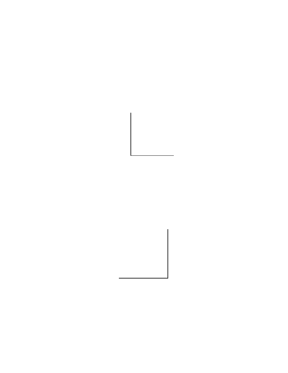
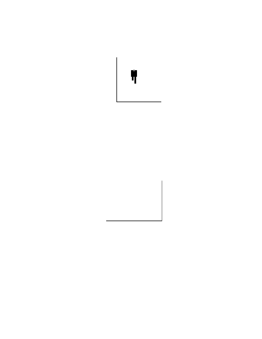
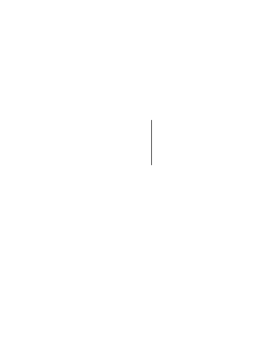
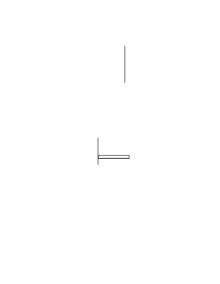
14. Three identical uniform rods are each acted on by two or more forces, all perpendicular to
the rods and all equal in magnitude. Which of the rods could be in static equilibrium if an
additional force is applied at the center of mass of the rod?
•
......
......
......
......
......
......
......
......
......
......
......
......
.............
..........
............
..........
•
......
......
......
......
......
......
......
......
......
......
......
......
.............
..........
............
..........
•
...........
...........
...........
...........
...........
...........
.................
..
...
..
..
..
.
.......
.......
.......
.
1
•
......
......
......
......
......
......
......
......
......
......
......
......
.............
..........
............
..........
•
...........
...........
...........
...........
...........
...........
.................
...
...
..
..
..
.......
.......
.......
.
2
•
......
......
......
......
......
......
......
......
......
......
......
......
.............
..........
............
..........
•
...........
...........
...........
...........
...........
...........
.................
..
..
...
..
..
.
.......
.......
.......
.
•
......
......
......
......
......
......
......
......
......
......
......
......
.............
..........
............
..........
3
A. Only 1
B. Only 2
C. Only 3
D. Only 1 and 2
E. All three
ans: C
15. A 160-N child sits on a light swing and is pulled back and held with a horizontal force of 100 N.
The magnitude of the tension force of each of the two supporting ropes is:
A. 60 N
B. 94 N
C. 120 N
D. 190 N
E. 260 N
ans: B
16. The diagram shows a stationary 5-kg uniform rod (AC), 1 m long, held against a wall by a
rope (AE) and friction between the rod and the wall. To use a single equation to find the
force exerted on the rod by the rope at which point should you place the reference point for
computing torque?
.............
.....
.............
.....
.............
.....
.............
.....
.............
.....
.............
.....
.............
.....
.............
.....
.............
.....
.............
.....
.............
.....
.............
.....
.............
.....
.............
.....
.............
.....
.............
.....
.............
.....
............
...........
............
............
...........
............
...........
............
...........
............
...........
............
...........
............
...........
............
...........
............
...........
............
...........
............
...........
............
...........
............
............
.........
•
A
•
B
•
C
•
D
•
E
ans: C
Chapter 12:
EQUILIBRIUM AND ELASTICITY
179
17. A picture P of weight W is hung by two strings as shown. The magnitude of the tension force
of each string is T . The total upward pull of the strings on the picture is:
.......
.......
.....
.......
.......
.....
.......
.......
.....
.......
.......
.....
.......
.......
.....
.......
.......
.....
.......
.......
.....
.......
.......
.....
.......
.......
.....
.......
.......
.....
.......
.......
.....
.......
.......
.....
.......
.......
.....
.......
.......
.....
.......
.......
.....
.......
.......
.....
.......
.......
.....
.......
.......
.....
.......
.......
.....
.......
.......
.....
.......
.......
.....
.......
.......
.....
.......
.......
.....
.......
.......
.....
.......
.......
.....
.......
.......
.....
.......
.......
.....
.......
.......
.....
.......
.......
.....
.......
.......
.....
.......
.......
.....
.......
.......
.....
.......
.......
.....
P
.........
.........
.........
.........
.........
.........
.........
.........
.........
.........
.........
....
.
..
.
..
.
..
..
.
..
.
..
.
..
.
..
.
..
..
.
..
.
..
.
..
.
..
.
..
..
.
..
.
..
.
..
.
..
.
..
..
.
..
.
..
.
..
.
..
.
..
..
.
..
.
..
.
..
.
..
.
..
..
.
..
.
..
.
•
•
•
•
......
.....
....
...
..
..
..
..
..
..
..
.
..
.
......
.......
.......
.......
........
.
θ
θ
T
T
A. 2W cos θ
B. T sin θ
C. T cos θ
D. 2T sin θ
E. 2T cos θ
ans: D
18. A picture can be hung on a wall with string in three different ways, as shown. The magnitude
of the tension force of the string is:
........
........
........
........
........
........
........
........
........
........
........
........
........
.......................
..............
..............
..............
..............
..............
..............
.......
•
•
•
I
......
......
......
......
......
......
......
......
......
......
......
......
......
......
...
......
......
......
......
......
......
......
......
......
......
......
......
......
......
...
••
•
II
...........
...........
...........
...........
...........
...........
...........
.......................
....................
....................
..................
•
•
•
III
A. least in I
B. greatest in I
C. greatest in II
D. least in III
E. greatest in III
ans: E
19. A uniform plank is supported by two equal 120-N forces at X and Y, as shown. The support
at X is then moved to Z (half-way to the plank center). The supporting forces at Y and Z are
then:
.......
.......
.....
.......
.......
.....
.......
.......
.....
.......
.......
.....
.......
.......
.....
.......
.......
.....
.......
.......
.....
.......
.......
.....
.......
.......
.....
.......
.......
.....
.......
.......
.....
.......
.......
.....
.......
.......
.....
.......
.......
.....
.......
.......
.....
.......
.......
.....
.......
.......
.....
.......
.......
.....
.......
.......
.....
.......
.......
.....
.......
.......
.....
.......
.......
.....
.......
.......
.....
.......
.......
.....
.......
.......
.....
.......
.......
.....
.......
.......
.....
.......
.......
.....
.......
.......
.....
.......
.......
.....
.......
.......
.....
.......
.......
.....
.......
.......
.....
.......
.......
.....
.......
.......
.....
.......
.......
.....
.......
.......
.....
...........................
........................................................................
.........
.........
..
...........................
........................
....
....
....
....
....
....
.................
..............
.............
X
Y
Z
•
A. F
Y
= 240 N, F
Z
= 120 N
B. F
Y
= 200 N, F
Z
= 40 N
C. F
Y
= 40 N, F
Z
= 200 N
D. F
Y
= 80 N, F
Z
= 160 N
E. F
Y
= 160 N, F
Z
= 80 N
ans: D
180
Chapter 12:
EQUILIBRIUM AND ELASTICITY
20. A uniform rod AB is 1.2 m long and weighs 16 N. It is suspended by strings AC and BD as
shown. A block P weighing 96 N is attached at E, 0.30 m from A. The magnitude of the tension
force of the string BD is:
.......
.......
.
.......
.......
.
.......
.......
.
.......
.......
.
.......
.......
.
.......
.......
.
.......
.......
.
.......
.......
.
.......
.......
.
.......
.......
.
.......
.......
.
.......
.......
.
.......
.......
.
.......
.......
.
.......
.......
.
.......
.......
.
.......
.......
.
.......
.......
.
.......
.......
.
.......
.......
.
.......
.......
.
.......
.......
.
.......
.......
.
.......
.......
.
.......
.......
.
.......
.......
.
.......
.......
.
.......
.......
.
.......
.......
.
.......
.......
.
.......
.......
.
•
•
•
•
•
•
A
B
C
D
E
P
A. 8.0 N
B. 24 N
C. 32 N
D. 48 N
E. 80 N
ans: C
21. A 5.0-m weightless strut, hinged to a wall, is used to support an 800-N block as shown. The
horizontal and vertical components of the force of the hinge on the strut are:
......
...
..
..
..
..
.
..
.
..
.
.
.
.
.
.
.
.
.
.
.
.
.
.
.
.
.
.
.
.
.
.
.
.
..
.
.
............
..
..
..
..
.
..
.
.
.
.
.
.
.
.
.
.
.
.
.
.
..
.
.
.
.
.
.
.
.
..
.
.
....
..
..
.
.
.
.
.
.
.
..
.
.
.
..
............
...................
..
hinge
............
...
............
...
............
...
............
...
............
...
............
...
............
...
............
...
............
...
............
...
............
...
............
...
............
...
............
...
............
...
............
...
............
...
............
...
............
...
............
...
............
...
............
...
............
...
............
...
•
3 m
•
800 N
••••••••••••••••••••
••••••••••••••••••••
••••••••••••••••••••
••••••••••••••••••••
••••••••••••••••••••
••••••••••••••••••••
••••••••••••••••••••
••••••••••••••••••••
••••••••••••••••••••
••••••••••••••••••••
••••••••••••••••••••
••••••••••••••••••••
••••••••••••••••••••
••••••••••••
••
••
••
••
•••
•••••••••••••••••••••••••••
••
•••••••••••••
A. F
H
= 800 N, F
Y
= 800 N
B. F
H
= 600 N, F
Y
= 800 N
C. F
H
= 800 N, F
Y
= 600 N
D. F
H
= 1200 N, F
Y
= 800 N
E. F
H
= 0, F
Y
= 800 N
ans: B
22. A uniform plank is 6.0 m long and weighs 80 N. It is balanced on a sawhorse at its center. An
additional 160 N weight is now placed on the left end of the plank. To keep the plank balanced,
it must be moved what distance to the left?
A. 6.0 m
B. 2.0 m
C. 1.5 m
D. 1.0 m
E. 0.50 m
ans: B
Chapter 12:
EQUILIBRIUM AND ELASTICITY
181
23. A uniform 240-g meter stick can be balanced by a 240-g weight placed at the 100-cm mark if
the fulcrum is placed at the point marked:
A. 75 cm
B. 60 cm
C. 50 cm
D. 40 cm
E. 80 cm
ans: A
24. A ladder leans against a wall. If the ladder is not to slip, which one of the following must be
true?
............
.
............
.
............
.
............
.
............
.
............
.
............
.
............
.
............
.
............
.
............
.
............
.
............
.
............
.
............
.
............
.
............
.
............
.
............
.
............
.
............
.
............
.
............
.
............
.
............
.
............
.
............
.
............
.
............
.
............
.
............
.
............
.
............
.
............
.
............
.
............
.
............
.
............
.
••••••••••••••••••••••••••••••••••••••••••••••
••••••••••••••••••••••••••••••••••••••••••••••
•••••••••••••••••••••••••••••••••••••••••••••
••••••••••••••••••••••••••••••••••••••••••••••
•••••••••••••••••••••••••••••••••••••••••••••
••••••••••••••••••••••••••••••••••••••
A. The coefficient of friction between the ladder and the wall must not be zero
B. The coefficient of friction between the ladder and the floor must not be zero
C. Both A and B
D. Either A or B
E. Neither A nor B
ans: B
25. An 80-N uniform plank leans against a frictionless wall as shown. The magnitude of the torque
(about point P) applied to the plank by the wall is:
............
...
............
...
............
...
............
...
............
...
............
...
............
...
............
...
............
...
............
...
............
...
............
...
............
...
............
...
............
...
............
...
............
...
............
...
............
...
............
...
............
...
............
...
............
...
............
...
............
...
............
...
............
...
............
...
............
...
............
...
............
...
............
...
............
...
............
...
............
...
............
...
............
...
............
...
•••
••••
•••
•••
•••
•••
••••
•••
•••
•••
•••
•••
•••
•••
•••
•••
•••
•••
•••
•••
••••
•••
•••
•••
•••
••••
•••
•••
•••
•••
••••
•••
•••
•••
•••
••••
•••
•••
•••
•••
••••
•••
•••
•••
•••
•••
•••
••••
•••
•••
•••
•••
••••
•••
•••
•••
•••
••••
•••
•••
•••
•••
••••
•••
•••
•••
•••
•••
•••
•••
•••
•••
•••
•••
•••
•••
••••
•••
•••
•••
•••
••••
•••
•••
•••
•••
•••
•••
••••
•••
•••
•••
•••
•••
•••
•••
••
←−−−− 3 m −−−−→
↑|
||
4 m
||
|↓
•
P
A. 40 N
· m
B. 60 N
· m
C. 120 N
· m
D. 160 N
· m
E. 240 N
· m
ans: C
182
Chapter 12:
EQUILIBRIUM AND ELASTICITY
26. An 800-N man stands halfway up a 5.0-m long ladder of negligible weight. The base of the
ladder is 3.0 m from the wall as shown. Assuming that the wall-ladder contact is frictionless,
the wall pushes against the ladder with a force of magnitude:
............
...
............
...
............
...
............
...
............
...
............
...
............
...
............
...
............
...
............
...
............
...
............
...
............
...
............
...
............
...
............
...
............
...
............
...
............
...
............
...
............
...
............
...
............
...
............
...
............
...
............
...
............
...
............
...
............
...
............
...
............
...
............
...
............
...
............
...
............
...
............
...
............
...
............
...
...........
.......
..
..
.
..
.
.
.
.
.
.
.
.
.
..
..
............
.......
...
••••••••••••••••••••••••••••••••••••••••
••••••••••••••••••••••••••••••••••••••••
•••••••••••••••••••••••••••••••••••••••
••••••••••••••••••••••••••••••••••••••••
••••••••••••••••••••••••••••••••••••••••
••••••••••••••••••••••••••••••••••••••••
•••••••••••••••••••••••••••••••••••••••
••••••••••••••••••••••••••
3 m
A. 150 N
B. 300 N
C. 400 N
D. 600 N
E. 800 N
ans: B
27. A uniform ladder is 10 m long and weighs 400 N. It rests with its upper end against a frictionless
vertical wall. Its lower end rests on the ground and is prevented from slipping by a peg driven
into the ground. The ladder makes a 30
◦
angle with the horizontal. The magnitude of the
force exerted on the peg by the ladder is:
............
.......
............
.......
............
.......
............
.......
............
.......
............
.......
............
.......
............
.......
............
.......
............
.......
............
.......
............
.......
............
.......
............
.......
............
.......
............
.......
............
.......
............
.......
............
.......
............
.......
............
.......
............
.......
............
.......
............
.......
............
.......
............
.......
............
.......
............
.......
............
.......
............
.......
............
.......
............
.......
............
.......
......
.....
....
...
...
..
..
..
..
30
◦
••
••
••
•••
••
••
••
•••
••
••
••
•••
••
••
••
•••
••
••
••
•••
••
••
••
•••
••
••
••
•••
••
••
••
•••
••
••
••
•••
••
••
••
•••
••
••
••
••
•••
••
••
••
•••
••
••
••
•••
••
••
••
•••
••
••
••
•••
••
••
••
•••
••
••
••
•••
••
••
••
•••
••
••
••
•••
••
••
••
•••
••
••
••
•••
••
••
••
•••
••
••
••
•••
••
••
••
•••
••
••
••
•••
••
••
••
•••
••
••
••
•••
••
••
••
•••
••
••
••
••
•••
••
••
••
•••
••
••
••
•••
••
••
••
•••
••
••
••
•••
••
••
••
•••
••
••
••
•••
••
••
••
•••
••••
•••
•••
•••
•••
•••
•••
•••
•••
•••
•••
•
peg
A. zero
B. 200 N
C. 400 N
D. 470 N
E. 670 N
ans: D
Chapter 12:
EQUILIBRIUM AND ELASTICITY
183
28. A window washer attempts to lean a ladder against a frictionless wall. He finds that the ladder
slips on the ground when it is placed at an angle of less than 75
◦
to the ground but remains in
place when the angle is greater than 75
◦
. The coefficient of static friction between the ladder
and the ground:
A. is about 0.13
B. is about 0.27
C. is about 1.0
D. depends on the mass of the ladder
E. depends on the length of the ladder
ans: A
29. The 600-N ball shown is suspended on a string AB and rests against a frictionless vertical wall.
The string makes an angle of 30
◦
with the wall. The magnitude of the tension force of the
string is:
......
.....
....
...
...
..
..
..
..
..
..
..
..
..
.
..
.
..
.
..
.
..
..
.
.
.
.
..
.
.
.
.
.
.
.
.
.
.
.
.
.
.
.
.
.
.
.
.
.
..
.
.
.
.
.
.
.
.
..
.
.
.
.
.
.
.
.
.
.
.
.
.
.
.
.
.
..
.
.
.
.
.
.
..
.
..
.
..
..
.
..
.
..
..
..
..
....
............
............
...........
...........
.............
...............
.........................
.........................................
...........
.........
........
.......
.......
......
......
....
•
.......
.......
.......
.......
.......
.......
.......
......
............
................
. .....................
........
30
◦
.....
.
.
.
.
.
.
.
.
.
.
.
..
.
. ....
..
..
..
..
..
..
.
..............
.....
.................
•
•A
B
600 N
.......
.......
.......
.......
.......
.......
.......
.......
.......
.......
.......
.......
.......
.......
.......
.......
.......
.......
.......
.......
.......
.......
.......
.......
.......
.......
.......
.......
.......
.......
.......
.......
.......
.......
.......
.......
.......
.......
.......
.......
A. 690 N
B. 1200 N
C. 2100 N
D. 2400 N
E. none of these
ans: A
184
Chapter 12:
EQUILIBRIUM AND ELASTICITY
30. The 600-N ball shown is suspended on a string AB and rests against a frictionless vertical wall.
The string makes an angle of 30
◦
with the wall. The ball presses against the wall with a force
of mangitude:
......
.....
....
...
...
..
..
..
..
..
..
..
..
..
.
..
.
..
.
..
.
..
..
.
.
.
.
..
.
.
.
.
.
.
.
.
.
.
.
.
.
.
.
.
.
.
.
.
.
.
..
.
.
.
.
.
.
..
.
..
.
.
.
.
.
.
.
.
.
.
.
.
.
.
.
..
.
.
.
.
.
.
..
.
..
.
..
..
.
..
.
..
..
..
..
...
............
............
...........
...........
............
...............
.....................
.................................................
..........
.........
........
.......
.......
......
......
...
•
.......
.......
.......
.......
.......
.......
.......
......
...........
...............
... ......................
.......
30
◦
.....
.
.
.
.
.
.
.
.
.
.
.
.
..
. ....
..
..
..
..
..
..
.
...............
....
.................
•
•A
B
600 N
.......
.......
.......
.......
.......
.......
.......
.......
.......
.......
.......
.......
.......
.......
.......
.......
.......
.......
.......
.......
.......
.......
.......
.......
.......
.......
.......
.......
.......
.......
.......
.......
.......
.......
.......
.......
.......
.......
.......
.......
A. 120 N
B. 300 N
C. 350 N
D. 600 N
E. 690 N
ans: C
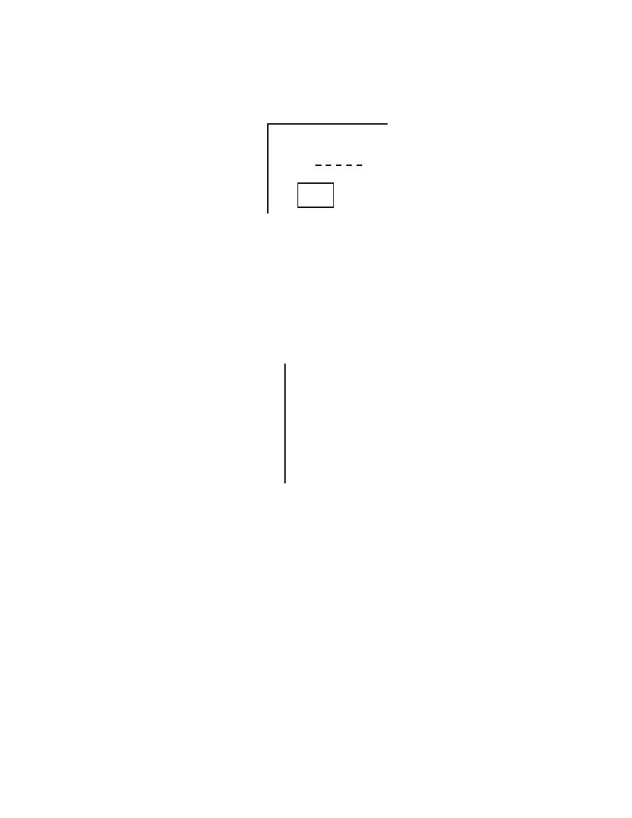
31. The uniform rod shown below is held in place by the rope and wall. Suppose you know the
weight of the rod and all dimensions. Then you can solve a single equation for the force of the
rope on the rod, provided you write expressions for the torques about the point:
....
..
....
..
..
....
..
....
..
..
....
..
....
..
..
...
..
..
....
..
.
....
..
....
..
..
....
..
....
..
..
....
..
....
..
..
....
..
....
..
..
....
..
....
..
..
....
..
....
..
..
....
..
....
..
..
....
..
....
..
..
....
..
....
..
..
....
..
....
..
..
.
.
.
.
.
.
.
.
.
.
.
.
.
.
.
.
.
.
.
.
.
.
.
.
.
.
.
.
.
.
.
.
.
.
.
.
.
.
.
.
.
.
.
.
.
.
.
.
.
.
.
.
.
.
.
.
.
.
.
.
.
.
.
.
.
.
.
.
.
.
.
.
.
.
.
.
.
.
.
.
.
.
.
.
.
.
.
.
.
.
.
.
.
.
.
.
.
.
.
.
.
.
.
.
.
.
.
.
.
.
.
.
.
.
.
.
.
.
.
.
.
.
.
.
.
.
.
.
.
.
.
.
.
.
.
.
.
.
.
.
.
.
.
.
.
.
.
.
.
.
.
.
.
.
.
.
.
.
.
.
.
.
.
.
.
.
.
.
.
.
.
.
.
.
.
.
.
.
.
.
.
.
.
.
.
.
.
.
.
.
.
.
.
.
.
.
.
.
.
.
.
.
.
.
.
.
.
.
.
.
.
.
.
.
.
.
.
.
.
.
.
.
.
.
.
.
.
.
.
.
.
.
.
.
.
• 1
•
2
•
3
•
4
A. 1
B. 2
C. 3
D. 4
E. 1, 2, or 3
ans: B
Chapter 12:
EQUILIBRIUM AND ELASTICITY
185
32. A 240-N weight is hung from two ropes as shown. The tension force of the horizontal rope has
magnitude:
.......
.......
.
.......
.......
.
.......
.......
.
.......
.......
.
.......
.......
.
.......
.......
.
.......
.......
.
.......
.......
.
.......
.......
.
.......
.......
.
.......
.......
.
.......
.......
.
.......
.......
.
.......
.......
.
.......
.......
.
.......
.......
.
.......
.......
.
.......
.......
.
.......
.......
.
.......
.......
.
.......
.......
.
.......
.......
.
.......
.......
.
.......
.......
.
.......
.......
.
.......
.......
.
.......
.......
.
.......
.......
.
.......
.......
.
.......
.......
.
.......
.......
.
.......
.......
.
.......
.......
.
.......
.......
.
.......
.......
.
.......
.......
.
.......
.......
.
•
•
•
•
..................................................................................................................... ...........
............
............
............
............
............
............
............
............
............
............
.............
............
............
............
............
..........
...........
...........
...........
...........
......
.....
...
...
...
..
.
30
◦
240 N
A. 0
B. 656 N
C. 480 N
D. 416 N
E. 176 N
ans: D
33. A 960-N block is suspended as shown. The beam AB is weightless and is hinged to the wall at
A. The tension force of the cable BC has magnitude:
......
...
..
..
..
..
.
..
..
.
.
.
.
.
.
.
.
.
.
.
.
.
.
.
.
..
.
.
.
.
.
.
.
..
..
............
..
..
..
..
..
.
.
.
.
.
.
.
.
.
.
.
.
.
.
.
..
.
.
.
.
.
.
.
.
..
..
....
..
..
.
..
.
.
.
.
..
.
.
..
..
.............
.................
..
.
.
.
.
..
.
.
.
.
..
.
.
.
.
.
..
.
.
.
.
..
.
.
.
.
.
..
.
.
.
.
..
.
.
.
.
..
.
.
.
.
.
..
.
.
.
.
..
.
.
.
.
.
..
.
.
.
.
..
.
.
.
.
..
.
.
.
.
.
..
.
.
.
.
..
.
.
.
.
.
..
.
.
.
.
..
.
.
.
.
.
..
.
.
.
.
..
.
.
.
.
..
.
.
.
.
.
..
.
.
.
.
..
.
.
.
.
.
..
.
.
.
.
..
.
.
.
.
.
..
.
.
.
.
..
.
.
.
.
..
.
.
.
.
.
..
.
.
.
.
..
.
.
.
.
.
..
.
.
.
.
..
.
.
.
.
.
..
.
.
.
.
..
.
.
.
.
..
.
.
.
.
.
..
.
.
.
.
..
.
.
.
.
.
..
.
.
.
.
..
.
.
.
.
.
..
.
.
.
.
..
.
.
.
.
..
.
.
.
.
.
..
.
.
.
.
..
.
.
•
...........
...........
...........
........................................................
...........
...........
...........
...........
...........
...
.
.
.
.
.
.
.
.
.
.
.
.
.
.
.
.
.
.
.
.
.
.
.
.
.
.
.
.
.
.
.
.
.
.
.
.
.
.
.
.
.
.
.
.
.
.
.
.
.
.
.
.
.
.
.
.
.
.
.
.
.
.
.
.
.
.
.
.
.
.
.
.
.
.
.
.
.
.
.
.
.
.
.
.
.
.. .....
......
......
......
......
......
......
......
......
................................................
960 N
↑
|
3 m
|
↓
←−−−− 4 m −−−−→
A
B
C
............
...
............
...
............
...
............
...
............
...
............
...
............
...
............
...
............
...
............
...
............
...
............
...
............
...
............
...
............
...
............
...
............
...
............
...
............
...
............
...
............
...
••••••••••••••••••••••••••••••••••••••••••••••••••••••••••••••••••••••••••••••••••••••••••••••••••••••••••••••••••••••••••••••••••••••••••••••••••••••••••••••••••••••••••••••••••••••••••••••••••••
A. 720 N
B. 1200 N
C. 1280 N
D. 1600 N
E. none of these
ans: D
186
Chapter 12:
EQUILIBRIUM AND ELASTICITY
34. A horizontal beam of weight W is supported by a hinge and cable as shown. The force exerted
on the beam by the hinge has a vertical component that must be:
......
...
..
..
..
..
..
.
.
..
.
.
.
.
.
.
.
.
.
.
.
.
.
..
.
.
.
.
.
.
.
.
.
.
..
.
............
..
..
.
..
.
.
..
.
.
.
.
.
.
.
.
.
.
.
.
.
..
.
.
.
.
.
.
.
.
.
.
..
.
....
..
.
..
.
.
.
.
.
.
.
.
.
.
.
..
.............
..................
..
hinge
.
.
.
.
.
.
..
.
.
.
.
..
.
.
.
.
.
..
.
.
.
.
..
.
.
.
.
..
.
.
.
.
.
..
.
.
.
.
..
.
.
.
.
.
..
.
.
.
.
..
.
.
.
.
.
..
.
.
.
.
..
.
.
.
.
..
.
.
.
.
.
..
.
.
.
.
..
.
.
.
.
.
..
.
.
.
.
..
.
.
.
.
.
..
.
.
.
.
..
.
.
.
.
..
.
.
.
.
.
..
.
.
.
.
..
.
.
.
.
.
..
.
.
.
.
..
.
.
.
.
.
..
.
.
.
.
..
.
.
.
.
..
.
.
.
.
.
..
.
.
.
.
..
.
.
.
.
.
..
.
.
.
.
..
.
.
.
.
.
..
.
.
.
.
..
.
.
.
.
..
.
.
.
.
.
..
.
.
.
.
..
.
.
.
.
.
..
.
.
.
.
..
.
.
.
.
.
..
.
.
.
.
..
.
.
.
.
..
.
.
.
.
.
..
.
.
.
.
..
•
cable
...........
...........
...........
...........
...........
...........
.................
...
..
...
..
..
.......
.......
.......
.
W
............
...
............
...
............
...
............
...
............
...
............
...
............
...
............
...
............
...
............
...
............
...
............
...
............
...
............
...
............
...
............
...
............
...
............
...
............
...
............
...
............
...
••••••••••••••••••••••••••••••••••••••••••••••••••••••••••••••••••••••••••••••••••••••••••••••••••••••••••••••••••••••••••••••••••••••••••••••••••••••••••••••••••••••••••••••••••••••••••••••••••••
A. nonzero and up
B. nonzero and down
C. nonzero but not enough information given to know whether up or down
D. zero
E. equal to W
ans: A
35. A 400-N uniform vertical boom is attached to the ceiling by a hinge, as shown. An 800-N
weight W and a horizontal guy wire are attached to the lower end of the boom as indicated.
The pulley is massless and frictionless. The tension force T of the horizontal guy wire has
magnitude:
.......
.......
.
.......
.......
.
.......
.......
.
.......
.......
.
.......
.......
.
.......
.......
.
.......
.......
.
.......
.......
.
.......
.......
.
.......
.......
.
.......
.......
.
.......
.......
.
.......
.......
.
.......
.......
.
.......
.......
.
.......
.......
.
.......
.......
.
.......
.......
.
.......
.......
.
.......
.......
.
.......
.......
.
.......
.......
.
.......
.......
.
.......
.......
.
.......
.......
.
.......
.......
.
.................
........
.......
.......
...
..
..
..
..
.
.
.
.
.
.
.
.
.
.
.
.
..
.
.
..
.
..
..
..
..
...
......
......
.......
... ....
.
.
..
.............
...................
.....
..
..
..
.
.
.
.
hinge
...........
............
...............
..............................................................
.........
.......
.......
......
.......
......
.....
...
...
..
..
..
..
..
..
..
..
..
.
..
..
..
.
.
..
.
.
.
.
.
.
.
.
.
.
.
.
.
.
.
.
.
.
.
.
.
.
.
.
.
.
.
..
.
.
.
.
.
.
.
.
.
.
.
.
.
.
.
.
.
.
.
..
.
..
..
..
..
..
..
..
..
............
...........
.
pulley
..
..
..
..
..
..
..
..
..
..
..
..
..
..
..
..
..
..
..
..
..
..
..
..
..
..
..
..
..
..
..
..
..
..
..
..
..
..
..
..
..
..
..
..
..
..
..
..
..
..
..
..
..
..
..
..
..
..
..
..
..
..
..
..
..
..
..
..
..
..
..
..
..
..
..
..
..
..
..
..
..
..
..
..
..
..
..
..
..
..
..
..
..
..
..
..
..
..
..
..
..
..
..
..
..
..
..
..
......
......
......
......
......
......
......
......
......
......
......
•
•
...........
...........
...........
...........
...........
...........
...........
...
W = 800 N
......
.......
.......
........
..........
60
◦
guy wire
•••••••••••••••••••••••••••••
••••••••••••••••••••••••••••••
••••••••••••••••••••••••••••••
••••••••••••••••••••••••••••••
•••••••••••••••••••••••••••••
••••••••••••••••••••••••••••••
••••••••••••
boom (400 N)
A. 340 N
B. 400 N
C. 690 N
D. 800 N
E. 1200 N
ans: B
Chapter 12:
EQUILIBRIUM AND ELASTICITY
187
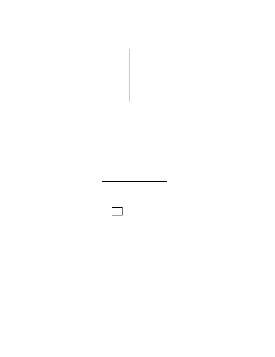
36. A picture is to be hung from the ceiling by means of two wires. Order the following arrangements
of the wires according to the tension force of wire B, from least to greatest.
.......
........
...
.......
........
...
.......
........
...
.......
........
...
.......
........
...
.......
........
...
.......
........
...
.......
........
...
.......
........
...
.......
........
...
.......
........
...
.......
........
...
.......
........
...
.......
........
...
.......
........
...
A
B
• cm
I
.......
........
...
.......
........
...
.......
........
...
.......
........
...
.......
........
...
.......
........
...
.......
........
...
.......
........
...
.......
........
...
.......
........
...
.......
........
...
.......
........
...
.......
........
...
.......
........
...
.......
........
...
A
B
• cm
II
.......
........
...
.......
........
...
.......
........
...
.......
........
...
.......
........
...
.......
........
...
.......
........
...
.......
........
...
.......
........
...
.......
........
...
.......
........
...
.......
........
...
.......
........
...
.......
........
...
.......
........
...
A
B
• cm
III
A. I, II, III
B. III, II, I
C. I and II tie, then III
D. II, I, III
E. all tie
ans: D
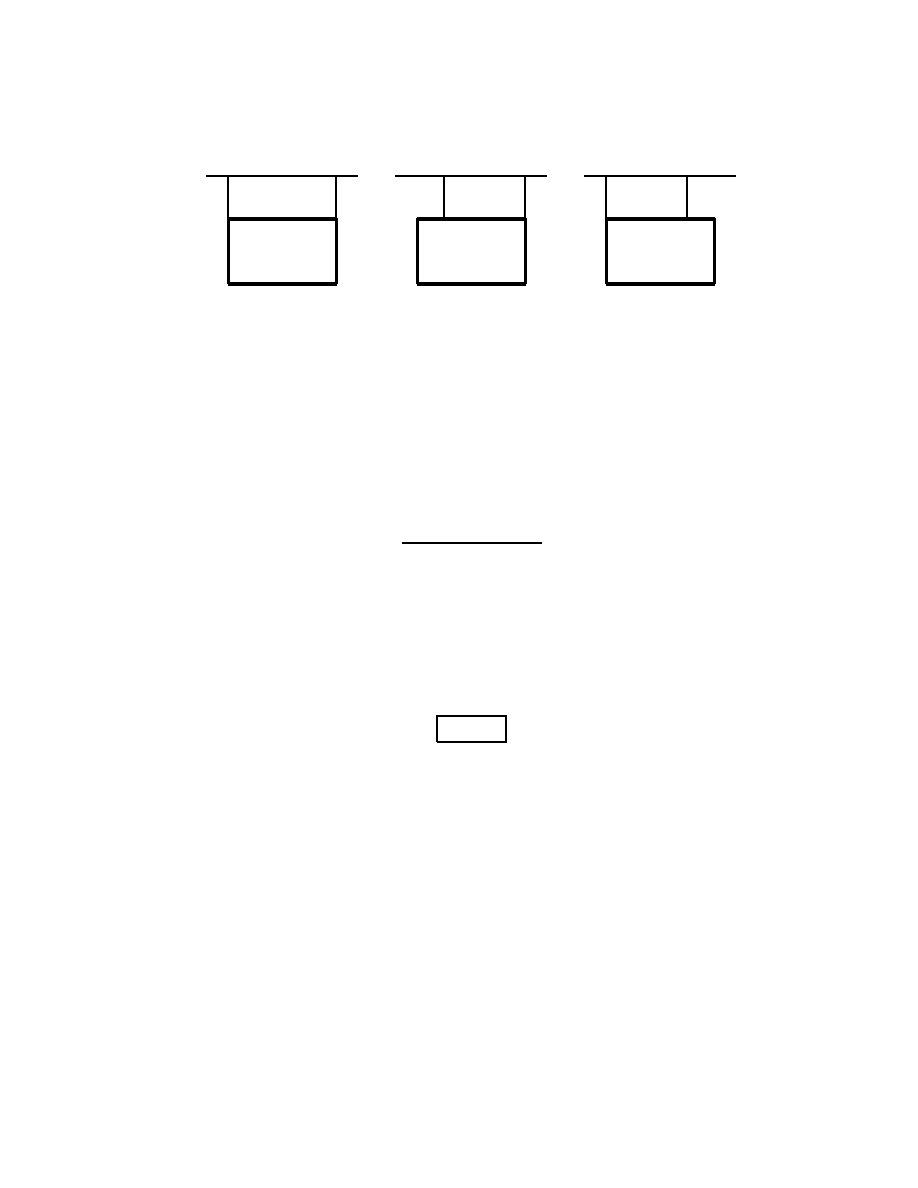
37. The pull P is just sufficient to keep the 14-N block and the weightless pulleys in equilibrium
as shown. The magnitude T of the tension force of the upper cable is:
......
...
...
..
..
..
..
.
..
.
..
..
.
.
..
.
.
.
.
.
.
.
.
.
.
.
.
.
.
.
.
..
.
.
.
.
.
.
.
.
.
.
.
..
.
.
..
..
.
..
..
............
...........
.............
.....................................................
.......
.......
.....
•
......
......
......
......
......
......
.
...........
...........
...........
....
...........
...........
...........
....
......
...
...
..
..
..
..
.
..
.
..
..
.
.
..
.
.
.
.
.
.
.
.
.
.
.
.
.
.
.
.
..
.
.
.
.
.
.
.
.
.
.
.
..
.
.
..
..
.
..
..
............
...........
.............
.....................................................
.......
.......
.....
•
......
......
......
......
......
......
.
...........
...........
...........
....
...........
...........
...........
....
...........
...........
...........
...........
...........
...........
...........
...........
...........
...........
...........
...........
...........
...........
...........
...........
.....
...........
...........
...........
...........
...........
...........
...........
...........
...........
..........
...........
...........
...........
....
14 lb
...........
...........
...........
...........
.................
...
...
..
..
..
.......
.......
.......
.
P
......
......
......
......
......
......
.
•
T
.......
.......
.
.......
.......
.
.......
.......
.
.......
.......
.
.......
.......
.
.......
.......
.
.......
.......
.
.......
.......
.
.......
.......
.
.......
.......
.
.......
.......
.
.......
.......
.
.......
.......
.
.......
.......
.
.......
.......
.
.......
.......
.
.......
.......
.
A. 14 N
B. 28 N
C. 16 N
D. 9.33 N
E. 18.7 N
ans: C
188
Chapter 12:
EQUILIBRIUM AND ELASTICITY
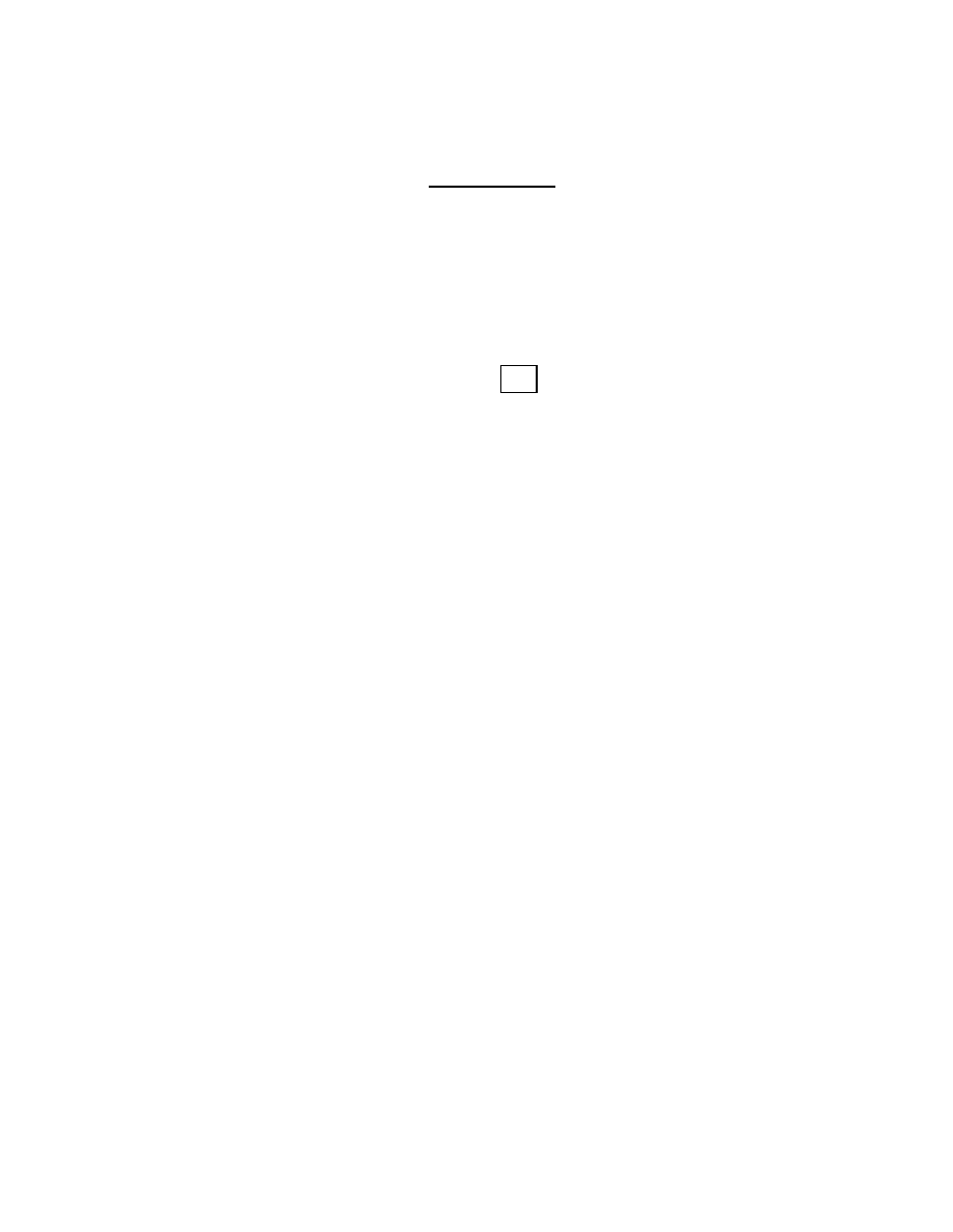
38. The ideal mechanical advantage (i.e. the ratio of the weight W to the pull P for equilibrium)
of the combination of pulleys shown is:
......
....
...
..
..
..
..
..
..
..
..
.
.
.
.
.
.
.
.
.
.
.
.
.
.
.
.
.
.
.
.
.
.
.
.
.
.
.
.
.
.
.
.
.
.
..
.
..
.
..
..
..
...........
............
.............
....................................................
.......
.......
.....
•
......
....
...
..
..
..
..
..
..
..
..
.
.
.
.
.
.
.
.
.
.
.
.
.
.
.
.
.
.
.
..
.
.
.
.
.
.
.
.
.
.
.
.
.
..
.
..
.
..
..
..
...........
............
.............
....................................................
.......
.......
.....
•
......
....
...
..
..
..
..
..
..
..
..
.
.
.
.
.
.
.
.
.
.
.
.
.
.
.
.
.
.
.
.
.
.
.
.
.
.
.
.
.
.
.
.
.
.
..
.
..
.
..
..
..
...........
............
.............
....................................................
.......
.......
.....
•
......
......
......
......
......
......
......
......
......
......
......
.......
•
...........
...........
...........
...........
...........
...........
.......
......
......
......
......
......
......
......
......
......
......
......
......
......
......
......
......
......
......
......
......
......
......
......
.......
•
...........
...........
...........
...........
...........
...........
.......
......
......
......
......
......
......
......
......
......
......
......
......
......
......
......
......
......
......
......
......
......
......
......
......
......
......
......
......
......
......
......
......
......
......
......
.......
•
...........
...........
...........
...........
...........
...........
.......
•
W
...........
...........
...........
...........
...........
..........
...
..
...
..
..
..
.
.......
.......
.......
.
P
.......
.......
.
.......
.......
.
.......
.......
.
.......
.......
.
.......
.......
.
.......
.......
.
.......
.......
.
.......
.......
.
.......
.......
.
.......
.......
.
.......
.......
.
.......
.......
.
.......
.......
.
.......
.......
.
.......
.......
.
A. 1
B. 2
C. 3
D. 4
E. 5
ans: D
39. Stress can be measured in:
A. N/m
2
B. N
·m
2
C. N/m
D. N
·m
E. none of these (it is unitless)
ans: A
40. Strain can be measured in:
A. N/m
2
B. N
·m
2
C. N/m
D. N
·m
E. none of these (it is unitless)
ans: E
41. Young’s modulus can be correctly given in:
A. N
·m
B. N/m
2
C. N
·m/s
D. N/m
E. joules
ans: B
Chapter 12:
EQUILIBRIUM AND ELASTICITY
189

42. Young’s modulus is a proportionality constant that relates the force per unit area applied
perpendicularly at the surface of an object to:
A. the shear
B. the fractional change in volume
C. the fractional change in length
D. the pressure
E. the spring constant
ans: C
43. Young’s modulus can be used to calculate the strain for a stress that is:
A. just below the ultimate strength
B. just above the ultimate strength
C. well below the yield strength
D. well above the yield strength
E. none of the above
ans: C
44. The ultimate strength of a sample is the stress at which the sample:
A. returns to its original shape when the stress is removed
B. remains underwater
C. breaks
D. bends 180
◦
E. does none of these
ans: C
45. A certain wire stretches 0.90 cm when outward forces with magnitude F are applied to each
end. The same forces are applied to a wire of the same material but with three times the
diameter and three times the length. The second wire stretches:
A. 0.10 cm
B. 0.30 cm
C. 0.90 cm
D. 2.7 cm
E. 8.1 cm
ans: B
46. A force of 5000 N is applied outwardly to each end of a 5.0-m long rod with a radius of 34.0 cm
and a Young’s modulus of 125
× 10
8
N/m
2
. The elongation of the rod is:
A. 0.0020 mm
B. 0.0040 mm
C. 0.14 mm
D. 0.55 mm
E. 1.42 mm
ans: D
190
Chapter 12:
EQUILIBRIUM AND ELASTICITY

47. A 4.0-m long steel beam with a cross-sectional area of 1.0
× 10
−2
m
2
and a Young’s modulus
of 2.0
× 10
11
N/m
2
is wedged horizontally between two vertical walls. In order to wedge the
beam, it is compressed by 0.020 mm. If the coefficient of static friction between the beam and
the walls is 0.70 the maximum mass (including its own) it can bear without slipping is:
A. 0
B. 3.6 kg
C. 36 kg
D. 71 kg
E. 710 kg
ans: E
48. Two supports, made of the same material and initially of equal length, are 2.0 m apart. A stiff
board with a length of 4.0 m and a mass of 10 kg is placed on the supports, with one support
at the left end and the other at the midpoint. A block is placed on the board a distance of
0.50 m from the left end. As a result the board is horizontal. The mass of the block is:
A. zero
B. 2.3 kg
C. 6.6 kg
D. 10 kg
E. 20 kg
ans: E
49. The bulk modulus is a proportionality constant that relates the pressure acting on an object
to:
A. the shear
B. the fractional change in volume
C. the fractional change in length
D. Young’s modulus
E. the spring constant
ans: B
50. A cube with edges exactly 2 cm long is made of material with a bulk modulus of 3.5
×10
9
N/m
2
.
When it is subjected to a pressure of 3.0
× 10
5
Pa its volume is:
A. 7.31 cm
3
B. 7.99931 cm
3
C. 8.00069 cm
3
D. 8.69 cm
3
E. none of these
ans: B
51. A cube with 2.0-cm sides is made of material with a bulk modulus of 4.7
× 10
5
N/m
2
. When
it is subjected to a pressure of 2.0
× 10
5
Pa the length of its any of its sides is:
A. 0.85 cm
B. 1.15 cm
C. 1.66 cm
D. 2.0 cm
E. none of these
ans: C
Chapter 12:
EQUILIBRIUM AND ELASTICITY
191

52. To shear a cube-shaped object, forces of equal magnitude and opposite directions might be
applied:
A. to opposite faces, perpendicular to the faces
B. to opposite faces, parallel to the faces
C. to adjacent faces, perpendicular to the faces
D. to adjacent faces, neither parallel or perpendicular to the faces
E. to a single face, in any direction
ans: B
53. A shearing force of 50 N is applied to an aluminum rod with a length of 10 m, a cross-sectional
area of 1.0
× 10
−5
m, and a shear modulus of 2.5
× 10
10
N/m
2
. As a result the rod is sheared
through a distance of:
A. zero
B. 1.9 mm
C. 1.9 cm
D. 19 cm
E. 1.9 m
ans: B
192
Chapter 12:
EQUILIBRIUM AND ELASTICITY
Document Outline
- TB_ch01.pdf
- TB_ch02.pdf
- TB_ch03.pdf
- TB_ch04.pdf
- TB_ch05.pdf
- TB_ch06.pdf
- TB_ch07.pdf
- TB_ch08.pdf
- TB_ch09.pdf
- TB_ch10.pdf
- TB_ch11.pdf
- TB_ch12.pdf
- TB_ch13.pdf
- TB_ch14.pdf
- TB_ch15.pdf
- TB_ch16.pdf
- TB_ch17.pdf
- TB_ch18.pdf
- TB_ch19.pdf
- TB_ch20.pdf
- TB_ch21.pdf
- TB_ch22.pdf
- TB_ch23.pdf
- TB_ch24.pdf
- TB_ch25.pdf
- TB_ch26.pdf
- TB_ch27.pdf
- TB_ch28.pdf
- TB_ch29.pdf
- TB_ch30.pdf
- TB_ch31.pdf
- TB_ch32.pdf
- TB_ch33.pdf
- TB_ch34.pdf
- TB_ch35.pdf
- TB_ch36.pdf
- TB_ch37.pdf
- TB_ch38.pdf
- TB_ch39.pdf
- TB_ch40.pdf
- TB_ch41.pdf
- TB_ch42.pdf
- TB_ch43.pdf
- TB_ch44.pdf
Wyszukiwarka
Podobne podstrony:
13 równowaga i spręzystość
13 równowaga i spręzystość
Równowaga kwasowo zasadowa fizjot3
APARATURA DO OCENY RÓWNOWAGI STATYCZNEJ
5a Równowaga kwasowo
12a Równowaga ciecz para w układach dwuskładnikowych (a)id 14224 ppt
Równowaga kwasowo zasadowa fizjot3
3 Równowagi jonowe w roztworach
Zaburzenia rownowagi wodnej do druku 9
Rozszerzalność Sprężystość
Sprężyny
F 2 Złącze p n stan równowagi
więcej podobnych podstron