
Z2
Atom
Race
GENERAL RULES
1. Where specified, assemble and disas-
semble the shock absorption system us-
ing the M
ARZOCCHI
special tools only, as
shown in the table below.
2. On reassembling the suspension system,
always use new seals.
3. Clean all metal parts with a special,
preferably biodegradable solvent, such
as trichloroethane or trichloroethylene.
4. Before reassembling, lubricate all parts
in contact with each other using silicone
fat spray.
5. Always grease the conic seal rings be-
fore reassembling.
6. Use wrenches with metric size only.
Wrenches with inch size might damage
the fastening devices even when their
size is similar to that of the wrenches in
metric size.
INSTRUCTIONS

Z2
Atom
Race
FAILURES, CAUSES AND REMEDIES
This paragraph reports some failures that may occur when using the fork. It also indicates possible causes and suggests a remedy. Always
refer to this table before doing any repair work.
Oil leaking through the bottom of slider
O-ring on the cartridge seal nut damaged
Replace the O-ring
Oil leaking through the top of slider
1. Oil seal is worn out
2. Stanchion tube is scored
3. Excessive dirt on oil seal
1. Replace oil seal
2. Replace oil seal and stanchions and
crown assembly
3. Clean the oil seal seat and replace oil seal
Fork has not been used for some time and
is locked out
Oil seals and dust seals tend to stick to
stanchion tube
Raise dust seal and lubricate stanchion
tube, dust seal and oil seal with silicone
grease
Fork rebounds too fast even though the
adjuster is set to hardest damping position
Right leg cartridge is faulty
Replace hydraulic cartridge
Excessive play of stanchions in the sliders
Pilot bushings are worn
Replace pilot bushings
FAILURES
CAUSES
REMEDIES
Fork does not react to adjustments
Legs inner parts are dirty
Carefully clean and replace oil
Fork does not react to rebound lock
LH fork cartridge faulty
Replace hydraulic cartridge

Z2
Atom
Race
DISC BRAKE SYSTEM ASSEMBLY
WARNING: If a disc brake system
is installed, it is absolutely forbidden
to loosen and remove original brake sup-
ports fixing pins. In fact, apart from retain-
ing Cantilever or V-brake levers, they also
play an important role in securing slider
bottom to slider-arch monolith. If needed,
replace these pins with screws (part no.
532979QF) available as spare parts.
Tighten the above screws to 10 Nm.
IMPORTANT: screw and pin threading is
treated to ensure hydraulic seal. Never
reuse screws and pins which have been
removed.
Assembling the brake caliper onto the slider
is a very delicate operation that should be
carried out with extreme care.
Improper assembly might overstress the
caliper supports which might break.
When installing the disc brake system, be
sure to properly follow the instructions given
by the manufacturer.
RECOMMENDATIONS FOR
MAINTENANCE
M
ARZOCCHI
forks are based on advanced
technology, supported by year-long experi-
ence in the field of professional mountain
biking. In order to achieve best results, we
recommend to check and clean the area
below the dust seal and the stanchion tube
after each use and lubricate with silicone
oil.
In general, M
ARZOCCHI
forks can offer top
performance from the start. However, in
some cases a short running-in period is
required (5-10 hours) for inner adjustments.
This running-in period will make fork life
longer and ensure fork top performance
over time.
IMPORTANT: change oil at least every
100 working hours.
Polished forks should be cleaned with
bodywork polish at regular intervals in
order to preserve their original finish.
INSTALLATION
Installing the fork on a bicycle is a very
delicate operation that should be carried
out with extreme care. The installation should
always be checked by one of our Technical
Service Centers.
WARNING: Steer tube/headset
mounting and adjustment must be
carried out in compliance with the headset
manufacturer’s instructions. Improper in-
stallation may jeopardize the safety of the
rider.
To replace it, contact one of our Technical
Service Centers with the required tools.
WARNING: In case of improper
installation of the steer tube into the
crown, the rider might lose control of his/
her bicycle, thus jeopardizing his/her safety.
Z2
Atom
Race
ADJUSTMENTS
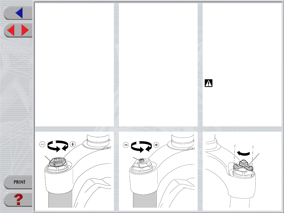
SPRING PRELOAD
The spring preload determines COMPRES-
SION damping and can be adjusted by
turning the knob (4) on top of the fork legs.
From the factory the fork is set at minimum
preload, i.e. the adjustment knob com-
pletely unscrewed counterclockwise. How-
ever, the springs are slightly preloaded to
help counteract static loads. By turning the
adjustment knob clockwise, the preload is
increased up to the maximum value equal
to 15 mm’s of spring preload. This adjust-
ment is essential in order to have the right
fork response for the rider’s weight and
riding style.
REBOUND ADJUSTMENT
(only right leg)
The right fork leg is equipped with an
adjuster screw (A) for REBOUND damp-
ing. Turning this adjuster clockwise into the
cartridge rod, changes the hydraulic set-
ting of the inner valves. In short, the amount
of adjustment applied on the piston in the
fluid determines the rate of damping.
To adjust, always start from the minimum
damping setting, i.e. unscrew completely
counterclockwise. About 8 turns - abt. 4 mm
of the adjustment - are possible.
REBOUND LIMITER
(only left leg)
In case of hard uphill path, fork leg rebound
can be locked for improved behavior.
Position the knob (3) on l.h. fork leg top to
“LOCK” to lock rebound limit in this posi-
tion; this also allows to decrease fork leg
height for optimal attitude uphill, thus sup-
porting suspension compression operation.
Reposition the knob to its original position
so that the fork will rebound and restart to
work as before.
WARNING: do not position to
“LOCK” when riding downhill as
available travel might not be enough, thus
jeopardizing rider’s safety
4
A
LOCK
3
Z2
Atom
Race
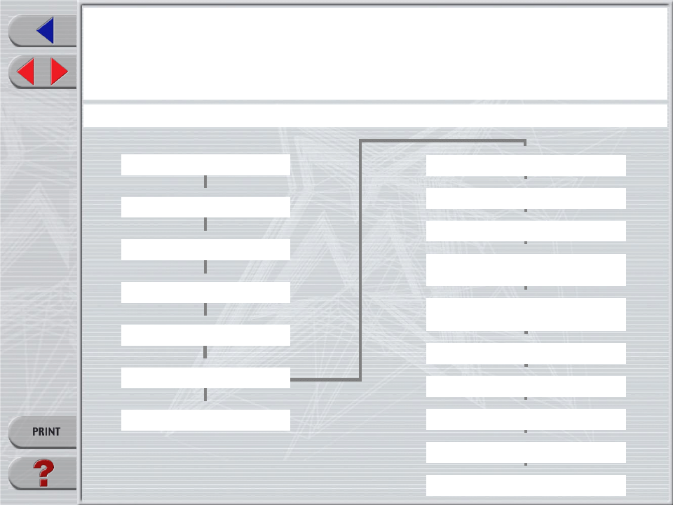
DISASSEMBLY
GENERAL
– The reference numbers given in this section relate to the components shown in the forks exploded view.
– Before starting any operation, please read the diagram below. It shows the quickest procedure and the exact sequence in which it should
be disassembled. Locate the part you need to remove in the diagram, then look at the arrows to determine which other parts you will
need to remove first.
DISASSEMBLY DIAGRAM
▲
▲
▲
▲
▲
▲
▲
▲
▲
▲
▲
▲
▲
▲
▲
▲
FOOT NUT FIG. 7
PILOT BUSHING AND
SEAL ASSEMBLY CHANGE
CARWON AND STANCHIONS ASSEMBLY
FIG. 9
SPRING CHANGE
PRELOAD KNOB FIG. 2
STANCHION TUBE CAP FIG. 4/5
SPRING FIG. 6
FORK OIL CHANGE
STOP RING FIG. 3
DUST SEAL FIG. 10
STOP RING FIG. 11
OIL SEAL FIG. 12
UPPER WASHER FIG. 13
PILOT BUSHING FIG. 14
COMPLETE HYDRAULIC CARTRIDGE FIG. 8
HYDRAULIC CARTRIDGE CHANGE
“LOCK” KNOB FIG. 1 (left leg)
Z2
Atom
Race
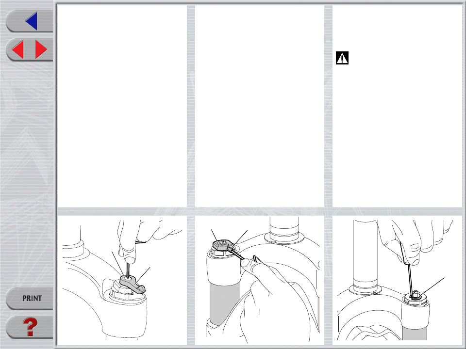
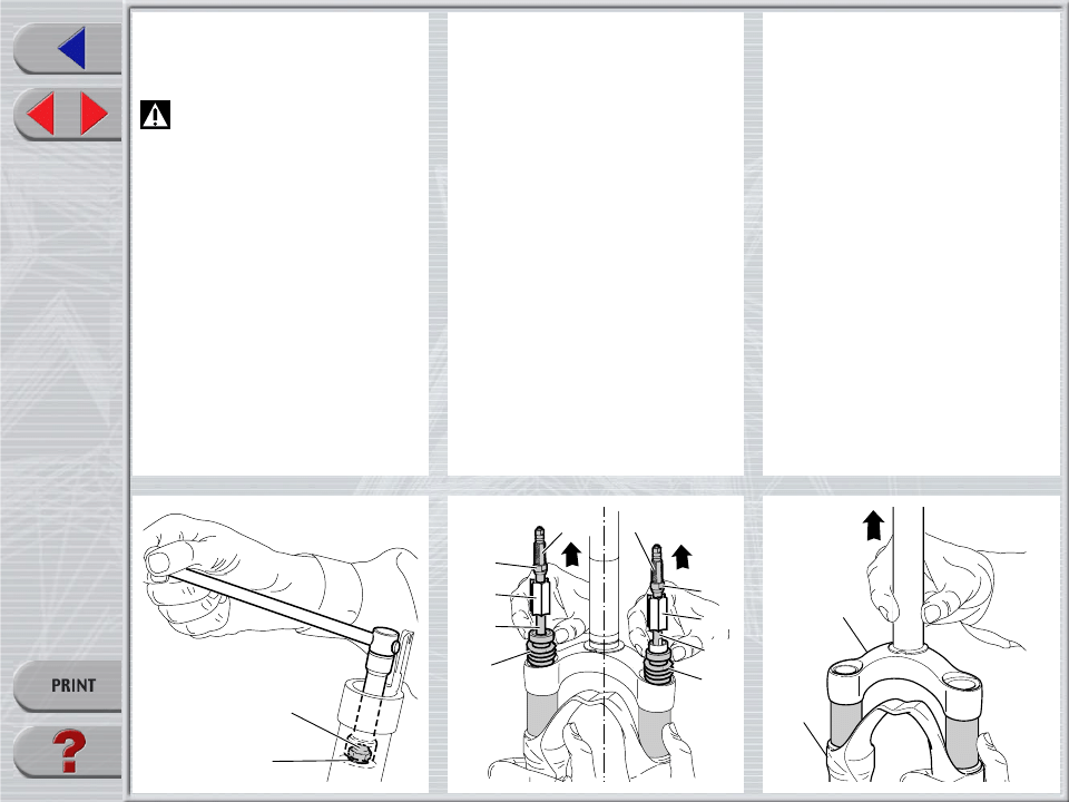
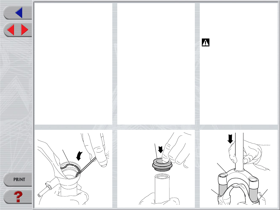
SPRING CHANGE
FIG. 1 (only left leg)
Loosen screw (2) and remove rebound
limiting knob (3).
FIG. 2
Set knob (4) of both legs to minimum
preload.
Loosen dowels (6) fastening the preload
knobs by means of a 1.5 mm Allen wrench.
Remove the knobs from the caps.
FIG. 3
Remove preload knob support stop rings
(5) from the top of the cap with a small
screwdriver.
WARNING: never use the fork with-
out upper cap otherwise the stan-
chion might detach from its slider.
3
2
4
6
5
Z2
Atom
Race
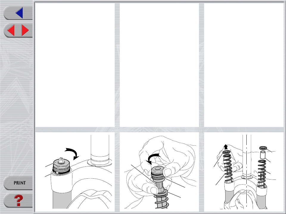
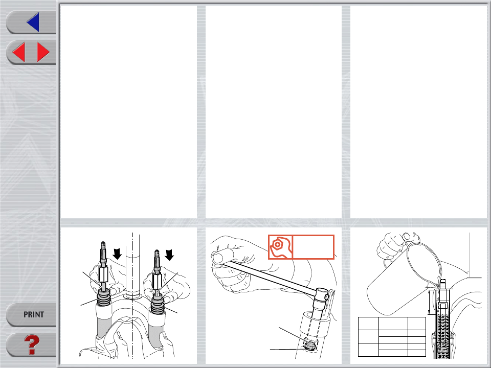
FIG. 4
Unscrew the caps (7) with a 21 mm socket
wrench.
Remove the caps complete with O-ring (8)
from the stanchions.
FIG. 5
Lock the check nuts (39) and remove the
caps (7) from hydraulic cartridges end
(12) and (28).
FIG. 6
Push the stanchions into the sliders.
Remove the lower washer (10) and the
spring (11) in both fork legs.
(only for travel of 80)
In LH fork leg, between lower washer (10)
and spring (11) there is a preload tube
(31).
Let all the oil drain into the fork leg. By
following this procedure, there is no need to
check the oil level.
Make all necessary changes.
7
8
7
39
12-28
11
10
11
31
10
Dx.
Sx.
Z2
Atom
Race
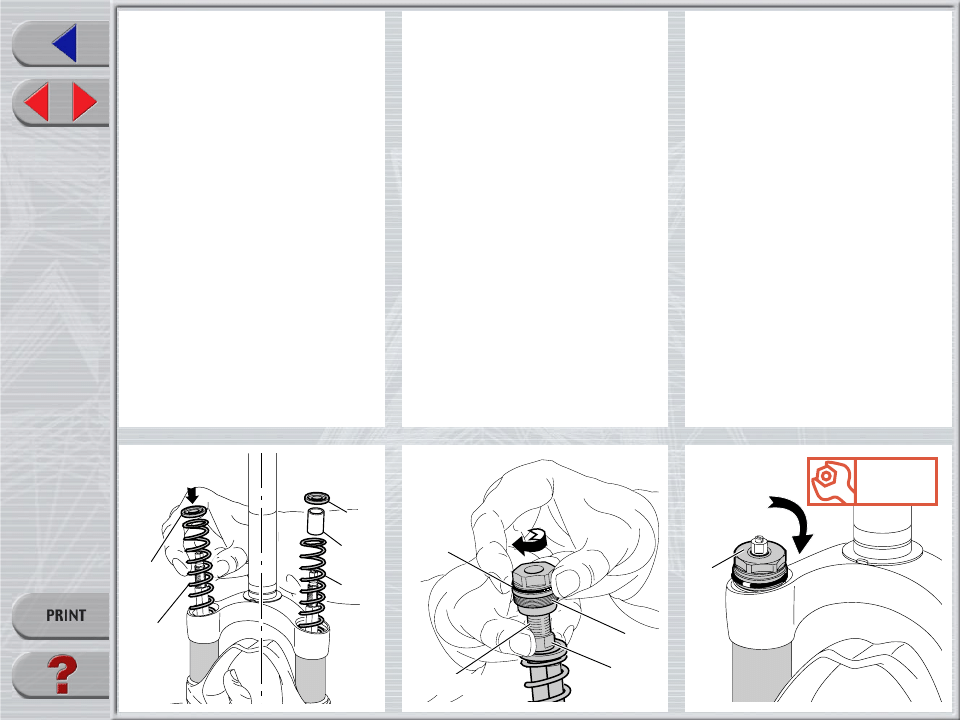
HYDRAULIC CARTRIDGE CHANGE
FIG. 7
Drain all oil from the fork legs.
WARNING: Remember to always
recycle any used oil.
To change the fork leg oil follow the proce-
dure as described in section “REASSEMBLY”
from Fig. 23 to Fig. 29.
Turn the fork leg upside-down and unscrew
the foot nut (20) complete with O-ring (19)
by the use of a 15 mm socket wrench.
FIG. 8
Remove hydraulic cartridges (12) and (28)
and keep the rebound spring.
IMPORTANT: cartridges fitted to forks
with a travel of 100 feature a rebound
spring (26) that is the same fitted in both
fork legs.
Rebound springs in forks with a travel of
80 are different: rebound spring (26) is in
the LH fork leg, while rebound spring (34)
is in the RH fork leg.
Remove the bottom washers (23, see ex-
ploded view) from inside the stanchions.
Replace the whole hydraulic cartridges.
NOTE: the hydraulic cartridge is supplied
with gaskets and lock nut (39). This model
features both support (40) for the preload
knob and spring guide (32).
These parts can be also ordered separately
(see exploded view).
PILOT BUSHING AND SEAL
ASSEMBLY CHANGE
FIG. 9
Pull the crown and stanchions assembly (1)
completely out of the sliders (18).
20
19
28
34-26
26
39
32
39
40
40
32
12
Dx.
Sx.
1
18
Z2
Atom
Race
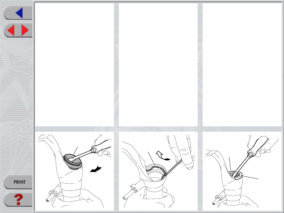
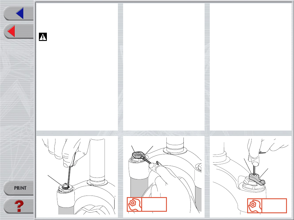
FIG. 10
Use a small screwdriver and remove the
dust seal (13) from the top of the slider.
FIG. 11
Remove the stop ring (14) from the slider
by placing the screwdriver bit in one of the
three openings on the stop ring and care-
fully lifting the ring out of place.
IMPORTANT: when removing the stop
ring, make sure not to damage its seat.
FIG. 12
Fit the slider protector (A) onto the slider
and remove the oil seal (15) with the help
of a large slot screwdriver.
IMPORTANT: when removing the oil seal,
make sure not to damage its seat. Once
removed the oil seals should not be used
again.
13
14
15
A
Z2
Atom
Race
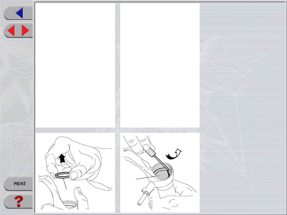
FIG. 13
Remove the upper washer (16) from the
slider.
FIG. 14
Fit the bit of a small screwdriver into the
upper edge slot of the pilot bushing (17)
and lift gently. Pull the bushing out of the
slider and make all necessary changes.
16
17
Z2
Atom
Race
REASSEMBLY
CAUTION: before reassembling, clean all
metal parts carefully with inflammable and
biodegradable solvent and dry them with
compressed air.
PILOT BUSHING AND SEAL
ASSEMBLY
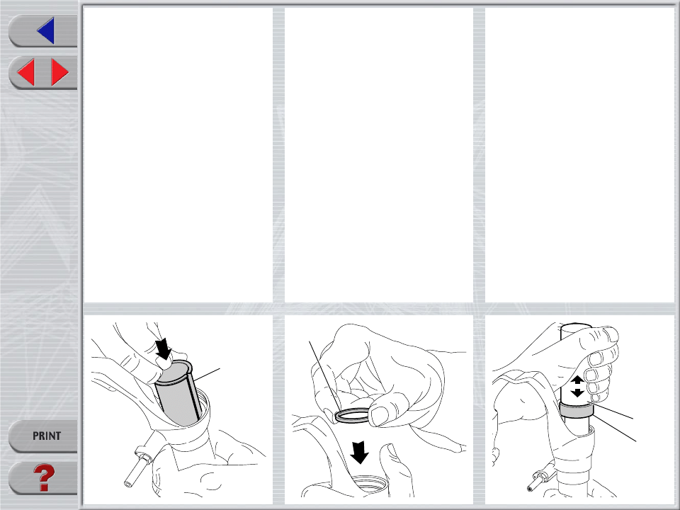
FIG. 15
Check that no dirt or debris is between
slider and bushing. Insert the pilot bushing
(17) into place so that it adheres to the
slider.
FIG. 16
Fit the upper washer (16) into the slider so
that it touches the pilot bushing.
FIG. 17
Lubricate the oil seal (15) and place it onto
the seal press (B) with the hollow side
toward the slider.
Press the oil seal into place until it touches
the lower washer by using the above seal
press.
17
16
15
B
Z2
Atom
Race
FIG. 18
Insert the stop ring (14) making sure it is
properly seated into place.
Use buffer (B) to properly seat the ring into
the slider.
FIG. 19
Lubricate the dust seals (13) and fit them
into the stanchions from the spring end.
CROWN AND STANCHIONS
ASSEMBLY
FIG. 20
Fit the stanchions and crown assembly (1)
with the dust seals in place gently into the
sliders seals.
WARNING: to avoid any damages
to sealing surfaces, keep the
stanchions duly lubricated and squared
into the sliders.
Check to see that the stanchion tube slides
unrestricted by cycling the fork up and
down several times.
The tube should slide freely inside the seal
assembly without any side play.
In the event it is too hard or too soft, repeat
the previous steps described above and
check components to ensure they are not
damaged.
Seat the dust seals (13) on top of the
sliders.
14
13
13
1
13
Z2
Atom
Race
HYDRAULIC CARTRIDGE RE-FITTING
FIG. 21
Push the stanchions up to slider bottom.
If removed, insert the bottom washers (23,
see exploded view) in the stanchion.
Slide in the cartridges fitted to forks with
travel of 100, the rebound spring (26).
Slide in the LH cartridge fitted to forks with
travel of 80, the rebound spring (26)
and the rebound spring (34) in the RH
cartridge;
Push the hydraulic cartridges (12) and
(28), complete with seals and retaining
parts, fully inside the stanchions.
FIG. 22
Grease the O-ring (19) on the foot nut (20)
and screw the nut on the threaded end of
the hydraulic cartridges.
Tighten to 11 Nm.
Check to verify that the stanchions slide
properly through the stroke by pumping
them up and down several times.
HOW TO FILL WITH OIL
FIG. 23
Pour the oil little by little when the stan-
chions are fully down and then pump with
the cartridges (12) and (28) rod so as to
have a better filling.
Cartridge is full when no air is detected
when pumping, in the completely closed
position.
Check that oil level is (H) from the top of the
stanchion tube in both fork legs.
Dx.
Sx.
28
34-26
26
12
20
19
Nm
11
H
Travel
Leg
H
(mm)
(mm)
80
100
Lh.
Rh.
Lh.
Rh.
50
50
30
40
Z2
Atom
Race
SPRING AND CAP
FIG. 24
Fit the springs (11) into the stanchions.
Slide the preload tube (31) in the LH fork
leg fitted to forks with a travel of 80, then
fit the washers (10).
Move the preload adjuster (9, see ex-
ploded view), in the cap, to the minimum
preload position.
FIG. 25
Lubricate the O-ring (27, see exploded
view) on the top of the preload knob sup-
port and the O-ring (8) on the cap (7).
Screw the cap (7), complete with pusher
(9), onto the cartridges (12) and (28) rod.
Screw cap all the way in.
Tighten check nut (39) against cap (7).
FIG. 26
Lift the stanchions and start the caps (7)
onto the threads by hand. Tighten the caps
to 20 Nm.
11
10
11
31
10
Dx.
Sx.
7
39
8
12-28
Nm
20
7
Z2
Atom
Race
FIG. 27
Fit the stop ring (5) of the preload knob
support and make sure it is properly seated
into place.
WARNING: never use the fork with-
out upper cap otherwise the stan-
chion might detach from its slider.
FIG. 28
Fit the preload knob (4) and secure it on the
support by tightening the grub screw (6) to
1.5 Nm.
FIG. 29 (left leg only)
Set rebound limiting knob (3) on RH leg
adjuster and tighten screw (2) to the torque
of 1,5 Nm.
5
4
6
Nm
1,5
3
2
Nm
1,5
Wyszukiwarka
Podobne podstrony:
Current Sociology 2002 Therborn 863 80(1)
ei 07 2002 s 78 80
2002 L MXR A 80
McBurney mysleć jak psycholog 2002 str 27 39, 72 73, 80 97
2002 L EXR C 80
2000 z2 atom bomb 80
ar 525 13 2002 1
ei 09 2002 s 80 82
2002 L MXC C 80
2002 L MXC A 80
2002 L X Fly 80
PiU P Z2
plik (80) ppt
więcej podobnych podstron