February 2008
1
US
National Oceanographic and
Atmospheric Administration
(NOAA) polar orbiting weather
satellites (POES) transmit data for produc-
tion of gray scale images of the ground
below them.
1
These automatic picture trans-
missions (APT) signals are sent at 137 MHz
and are available twice a day to anyone on
the earth. There are many free programs
available that can decode the satellite signals
and then produce color images on a personal
computer. I prefer APTDecoder by Patrik
Tast, available on the Internet.
2
Antennas for POES Satellite
Reception
The NOAA weather satellites are polar
orbiting, so they can and do appear at all
azimuth and elevation directions from any
ground location. An ideal ground-based
antenna for reception of NOAA satellite sig-
nals would be right-hand circularly polarized
(RHCP) and have no deep pattern minimums
within the hemisphere. Figure 1 shows
the ideal pattern shape of a ground-based
antenna for APT reception. It would have a
12 dB minimum toward zenith since the sat-
ellites will be approximately 12 dB stronger
when overhead as compared to their strength
when at the horizon due to path loss.
This ideal pattern cannot quite be obtained
for a ground-based receiving antenna for
VHF. But it is a useful guide to remind the
antenna designer that the ground-based
antenna pattern should have a minimum of
nulls within the hemisphere, with a maxi-
mum toward the horizon.
Four dipoles can be mounted as shown in
Figure 2 to produce a radiation pattern with
excellent RHCP at 0° elevation in the free
space radiation pattern as shown in Figure 3.
The design concept for this four dipole array
with hemispheric coverage with RHCP is
derived from the fundamental concept that
two dipoles, crossed, spaced a quarter wave
Double Cross — A NOAA Satellite
Downlink Antenna
An easy to build antenna for ground reception of NOAA weather or
amateur satellite signals.
Gerald Martes, KD6JDJ
Figure 1 — Ideal radiation pattern for a
ground-based antenna for reception of
NOAA weather satellite images.
Figure 2 — The four dipoles that make up
the Double Cross antenna prototype.
Figure 3 — The free space three
dimensional pattern of the Double Cross
closely matches our design goal.
Figure 4 — One pair of crossed dipoles
makes half a Double Cross.
apart, and fed in phase as shown in Figure
4 can be polarized to produce a pattern as
shown in Figure 5.
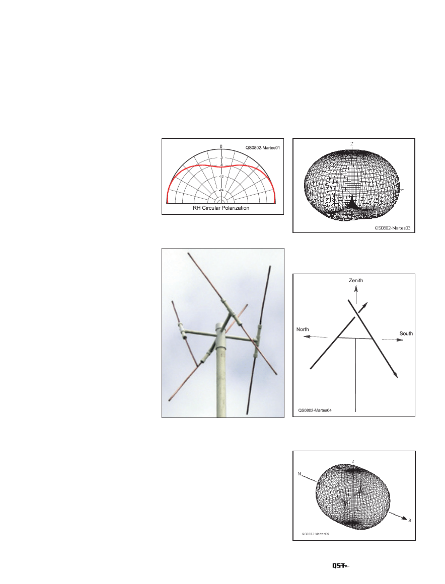
The pattern null along the X axis can
be filled in by including a second pair of
crossed dipoles as shown in Figure 6. If the
second pair is fed 90° later than the first pair,
the four dipole array has the excellent radia-
tion pattern shown in Figure 7.
Double Cross as an Amateur
Satellite Antenna
The Double Cross can also be built as
1
www.oso.noaa.gov/poesstatus/index.asp.
2
www.poes-weather.com/.
kd6JdJ
Figure 5 — Free space radiation pattern of
crossed dipoles.
2 February 2008
an antenna for amateur frequencies. Table 1
shows the dimensions for both NOAA and
amateur satellite bands. Note that circular
polarization toward the horizon is also use-
ful for terrestrial communication, since it
responds equally well to both vertical (for
FM) and horizontal (for SSB and CW)
polarization.
Making it Happen
One beneficial aspect of this Double
Cross antenna is that it is quite tolerant of
construction variations. That is, an antenna
in this configuration will almost always
work well even when the dimensions are
only close to the optimum design. The only
Table 1
Dimensions of Double Cross Array
(Inches)
Operating
Frequency (MHz) 137
145
435
Dipole length
38.25 37.125 12.125
Dipole diameter 0.375
0.375
0.25
Dipole spacing
21.5
20.5
6.75
Poly coax λ/4
14.25
13.5
4.5
phasing section
Figure 6 — Two pairs of crossed dipoles
become the Double Cross.
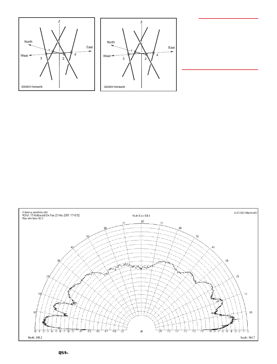
Figure 7 — The measured pattern of the Double Cross antenna closely matches the ideal of Figure 1.
Figure 8 — Dielectric support for the
dipoles and harness.
thing critical is the proper connection of the
harness to the dipoles.
Field testing with this antenna indicates
that it produces very little radiation pattern
nulling within the hemisphere. Pattern nulls
would be expected to produce dark hori-
zontal lines across the image. The images,
recorded with the Double Cross thus far
constructed and tested, have indicated that
very little image quality degradation is seen
as a result from elevation plane nulls from
ground reflection.
A Double Cross APT antenna can be
built by constructing a dielectric support
as shown in Figure 8 and attaching the
dipoles and harness, as described later, to
the dielectric support.
Build four dipoles from a convenient
conductor, each about 38 inches long, and
attach them to the supports. The dipole sup-
ports numbers 1 and 2 are separated by about
20 inches. The dipoles number 3 and 4 are
also separated by 20 inches. Each of the four
dipole supports is tilted 30° from vertical.
Dipoles 1 and 2 are fed in phase and with
the proper polarity, so the upward pointing
end of dipole #1 has the same polarity as
the downward pointing end of dipole 2. The
upward pointing end of dipole 3 has the
same polarity as the downward pointing end
of dipole 4.
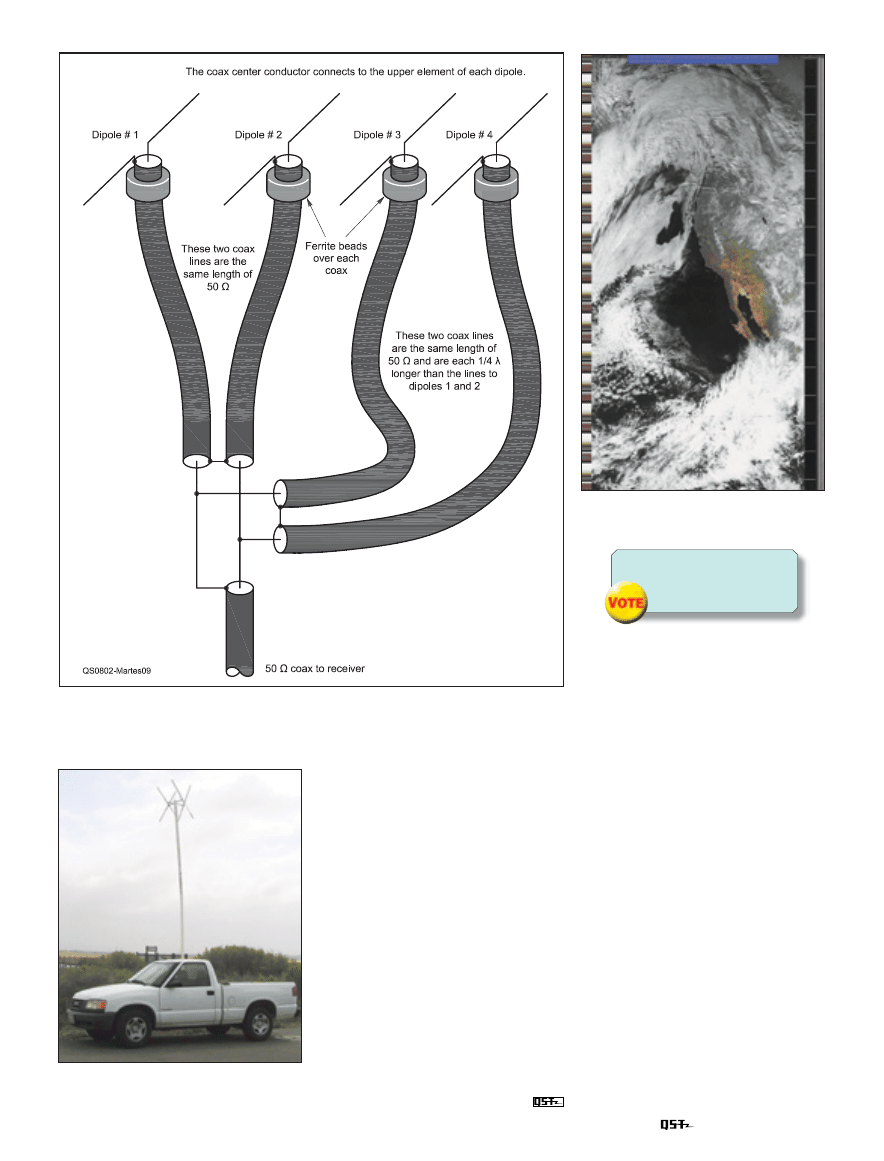
The input impedance of each of the
λ/2
dipoles when configured as shown will
be very close to 50
Ω. Each pair is wired
in series to have an impedance of 100
Ω.
After connecting the two pairs in parallel, as
shown in the harness diagram of Figure 9,
we end up with the desired 50
Ω for the run
to the radio.
February 2008
3
Figure 11 — NOAA satellite image from
Double Cross at 2 λ height.
Figure 9 — Harness for Double Cross using 50 Ω coax.
Figure 10 — Photograph of the Double
Cross antenna mounted 2 λ above ground,
at the beach in Southern California.
$IDYOUENJOYTHISARTICLE
#ASTYOURVOTEAT
WWWARRLORGMEMBERSONLY
QSTVOTEHTML
It Works!
The antenna works very well, either from
my home station or on the road, as shown in
Figure 10. A sample of the received signal is
shown in Figure 11.
Gerald Martes, KD6JDJ, has been licensed,
on and off since 1949. He received his first
license, and call KL7LL while in the USAF in
Alaska. He took the test again in the 1950s and
had the call K6LZC. Several years ago, he took
the General class exam and barely passed it
but is now KD6JDJ and promises not to let this
one lapse. He also held commercial First Class
Radiotelephone and Radiotelegraph licenses,
including CW at 20 WPM.
Gerald earned a BSEE from Pacific States
University and was employed as an antenna
design engineer from 1955 through 1970. He
then started his own electrical business and
never went back to engineering.
Gerald can be reached at 5061 Tripoli Ave,
Los Alamitos, CA 90720 or at
j.jmartes@
verizon.net.
kd6JdJ
Wyszukiwarka
Podobne podstrony:
Antena szczególnie przydatna do odbioru na niskich pasmach?verage
Double Cross Rozdział 3
Tabor Evans Longarm 231 Longarm and the Durango Double Cross
Antena typu arrow do satelitów
Double Cross Rozdział 1
Cross Ronald Anthony Droga do miasta Teelee
Obliczenia do metody hydraulicznej Cross
Antena do odbioru pośredniego
akumulator do volvo xc70 cross country 24 t xc awd 25 t xc awd
3G 4G antena własnymi rękami o zasięgu do 30 km
Radkiewicz M , Oblicza kina queer od cross dressingu do filmów transgenderowych
3G 4G antena własnymi rękami o zasięgu do 30 km
akumulator do volvo xc70 cross country 32
akumulator do volvo xc70 cross country 24 d5 xc awd 24 d5 awd
akumulator do volkswagen amorak double cab 20 tdi
Cross Ronald Anthony Droga do miasta Teelee
więcej podobnych podstron