
BMW E39 Euro-spec CELIS "Angel Eye" Head Light Installation
http://www.bmwdiy.info/celis-front/index.html
1 of 12
BMW
diy
.
INFO
E39 Euro-spec CELIS "Angel Eye"
Head Light Installation
Prepared by VietSB
Modified 01.04.04
NOTE
: Perform these steps at your own risk. All P/N's listed are a "best guess", so please double-check with your
local dealer. These mods and repairs were performed on my US-spec 1997 540iA (11/96 prod date, M62 engine) but
there is no guarantee they will work on other E39's. These instructions are p rovided for entertainment purposes
only!
BACKGROUND: This DIY covers the install of Euro-spec CELIS (aka Angel Eye or halo) assemblies on a pre-2001
E39 to mimic the newer-style 2001+ E39 head lights. Note that the Euro-spec a ssemblies do not have the small
side parking indicator, which is required for DOT-approval.
Required Parts:
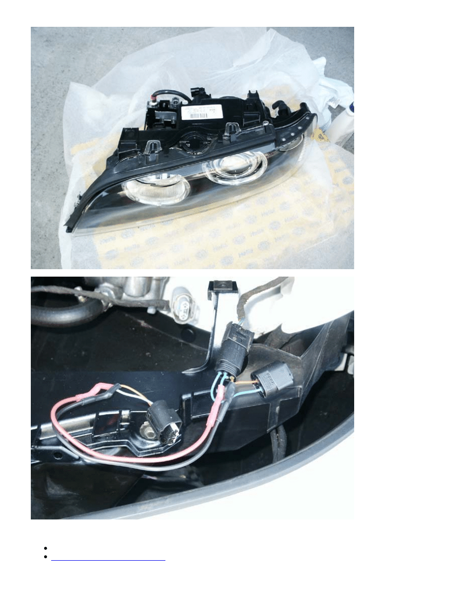
Hella Euro-spec Xenon CELIS clear-corner head light assemblies (pic below). A very complete list of the
different styles can be found on
BMWTips.com
).
Head light mounting brackets (should be included with head lights)
Pre-wired turn-signal/parking light Y-harness adapter (pic below). Detailed i nfo can be found on
BMWTips.com
. If you require the harness pieces, buy these harnesses from the dealer and assemble them
using the BMWTips.com instructions.
(Qty 2) P/N 63 12 0 025 497
(Qty 2) P/N 63 12 0 025 499
2 of 12
Recommended Parts:
Philips Ultinon 6000K Xenon HID bulbs (D2S)
Philips PY21W SilverVision bulbs
3 of 12
Hella resistor packs
-
Important!
Click and read the link to see if they are required on your vehicle.
Newer-style Hella/Philips ballasts -
Important!
Check Step 1 below to see if they need to be purchased. (I've
mainly noticed older-style ballasts on pre-2000 vehicles.)
Required Tools:
Ratchet, extension, 8mm socket
Flat-head screwdriver
Recommend Tools:
Rubber gloves
Magnetic pick-up tool and flashlight in case of an "incident"
Properly-sized pipe bending tool
Masking tape
6mm hex key
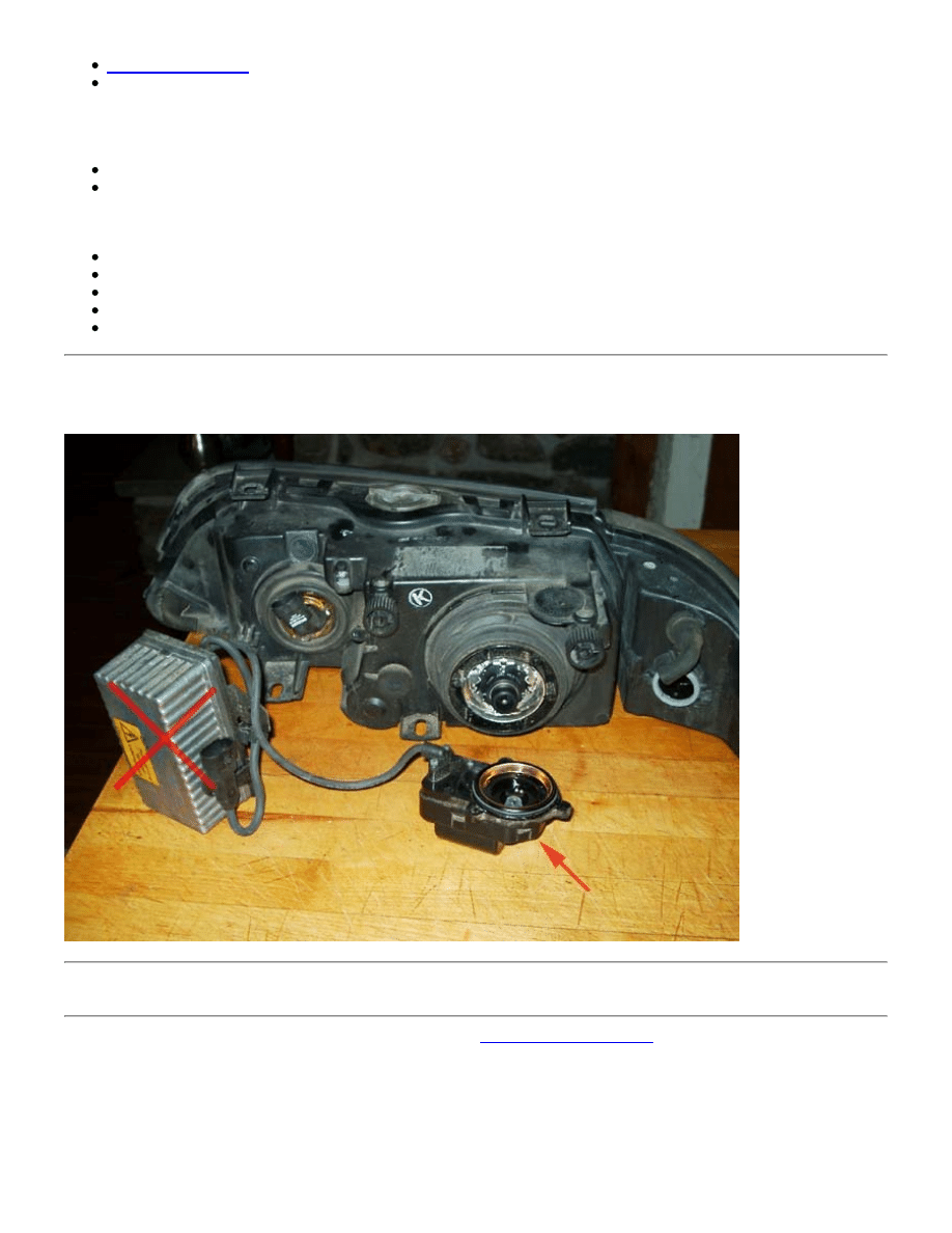
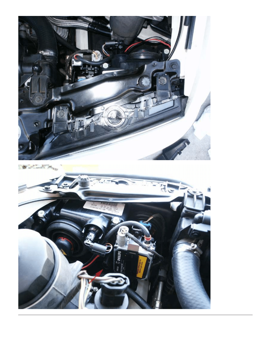
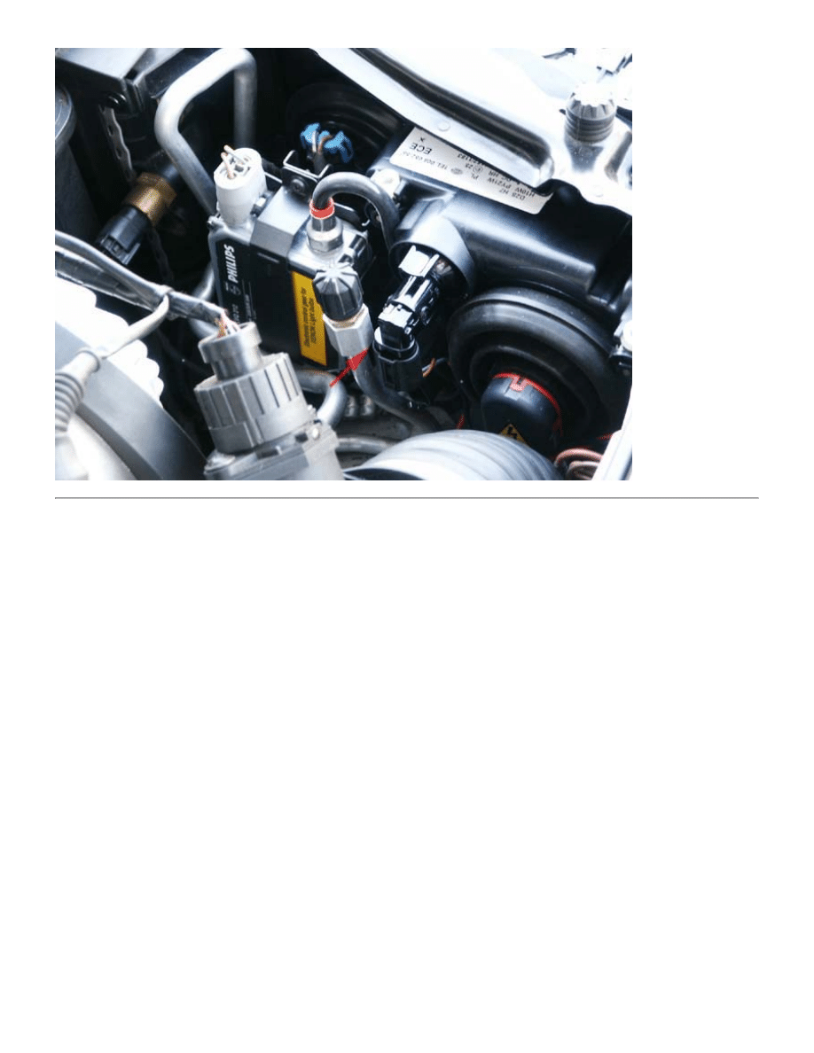
1. Check your existing ballasts. If they look like the one pictured below, they
will not work
since the new ballast
mounting bracket is sized for the newer-style ballasts and the bulb connector won't fit at all. Stop until you obtain
the correct ballasts.
2. Park against a wall and use masking tape to mark the approximate focus poi nt of the low beams for future
reference.
3. Remove the existing headlight assemblies. Refer to the
Head Light Removal DIY
if needed.
4 of 12
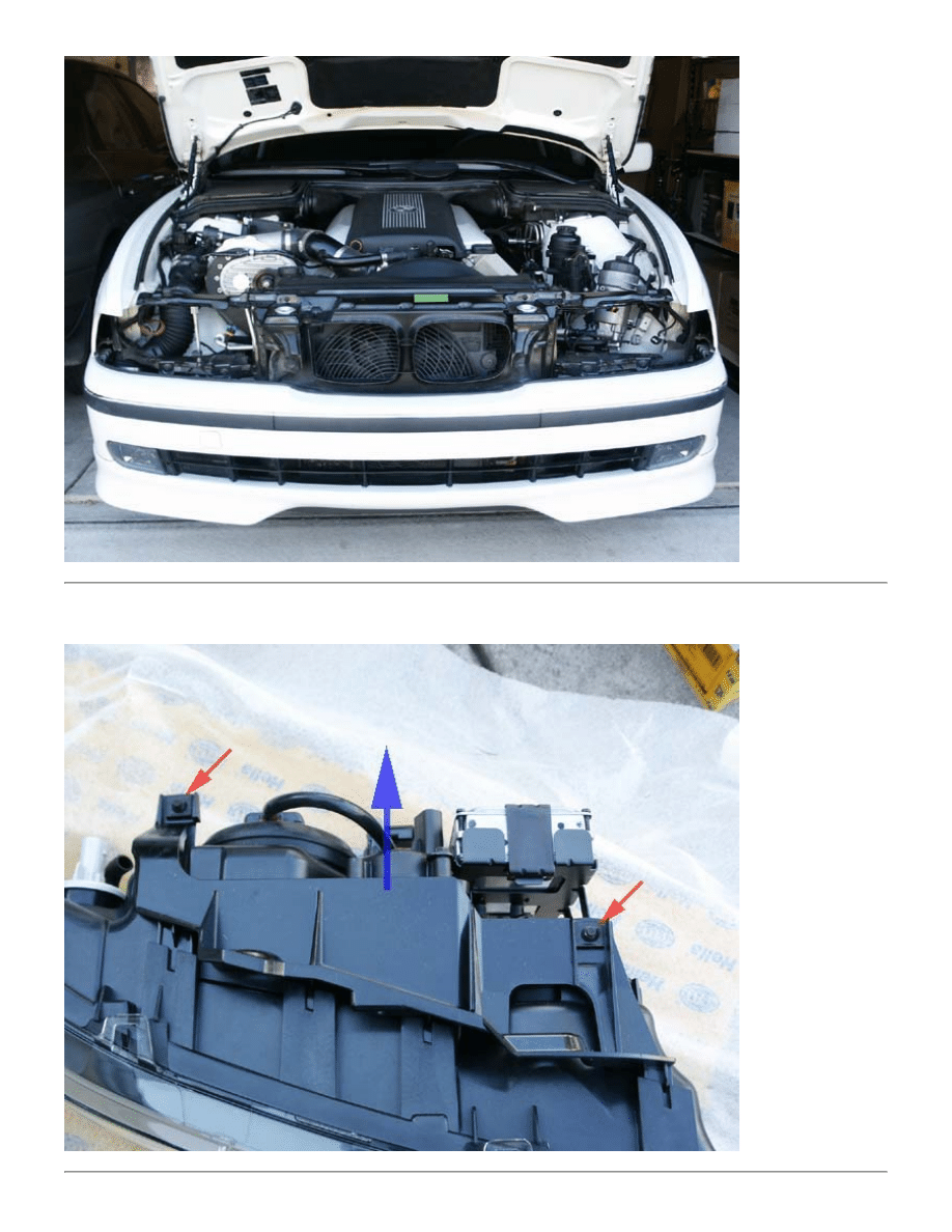
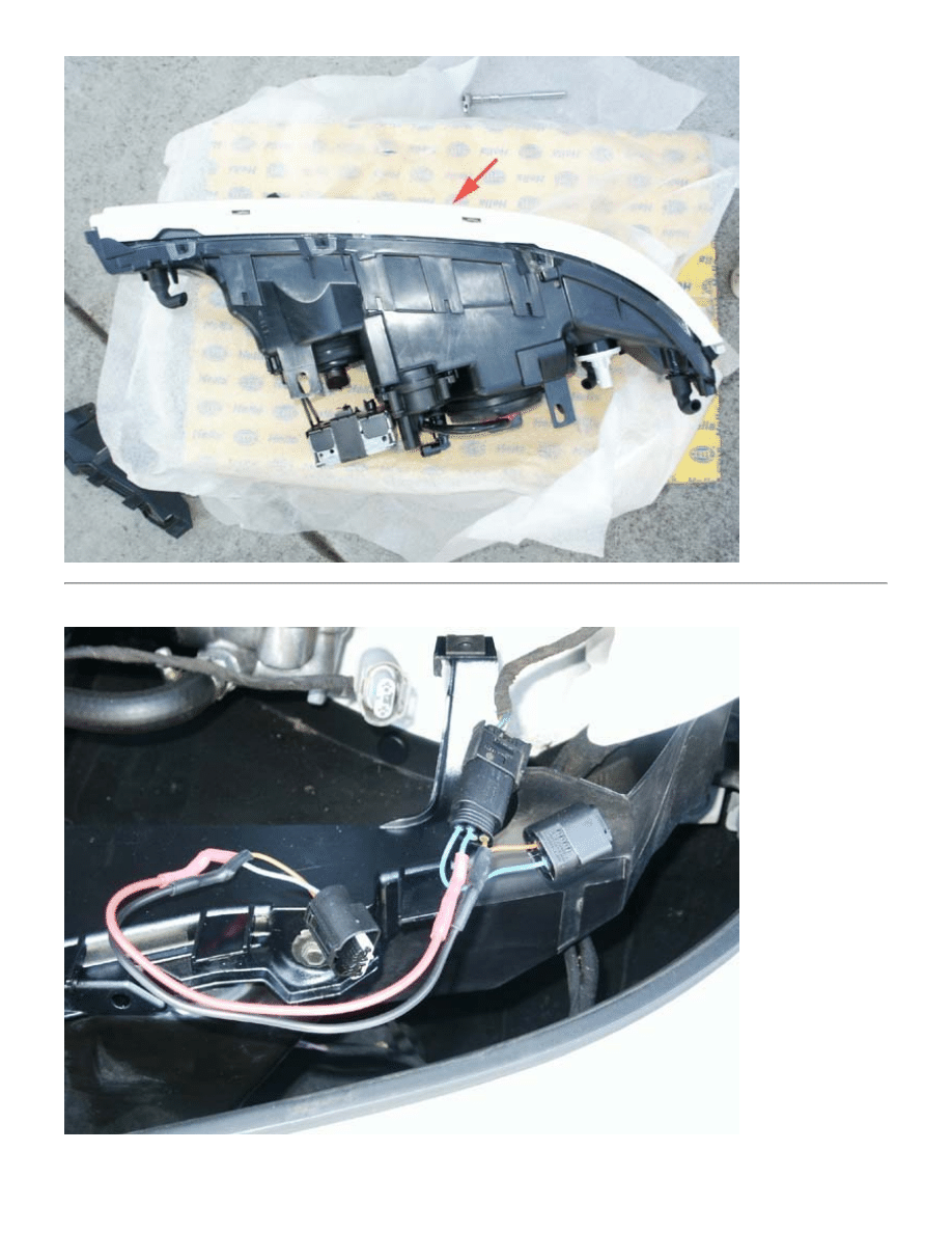
4. Remove the new mounting bracket from the CELIS assembly by removing the two screws (see red arrows) and
pulling it in the direction of the blue arrow.
5 of 12
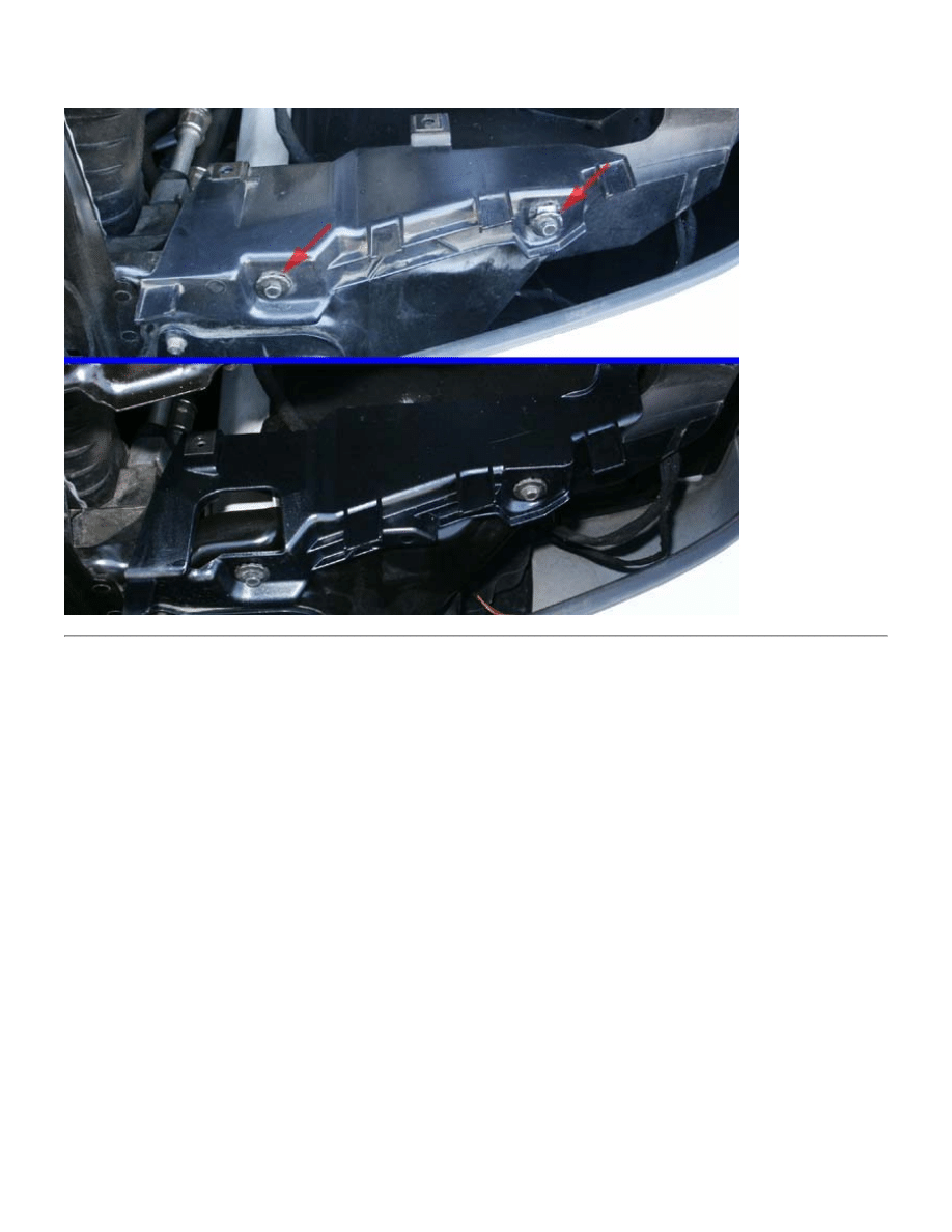
5. Remove the old mounting bracket on the car by removing the (2) screws (top pic) and replace it with the new
bracket (bottom pic).
IF THERE IS NOTHING WRONG WITH YOUR BRACKET, PLEASE REUSE YOUR EXISTING BRACKET
6. Install the body-colored trim piece from the old assembly onto the CELIS assembly. Be careful not to break the
fragile end-hook.
6 of 12
7. Use the Y-harness to split the existing combo turn-signal/parking light connector into two separate plugs.
iT Wagon Owners Note
: Some (approx) pre-2000 model vehicles had a differently-wired combo connector with only
7 of 12
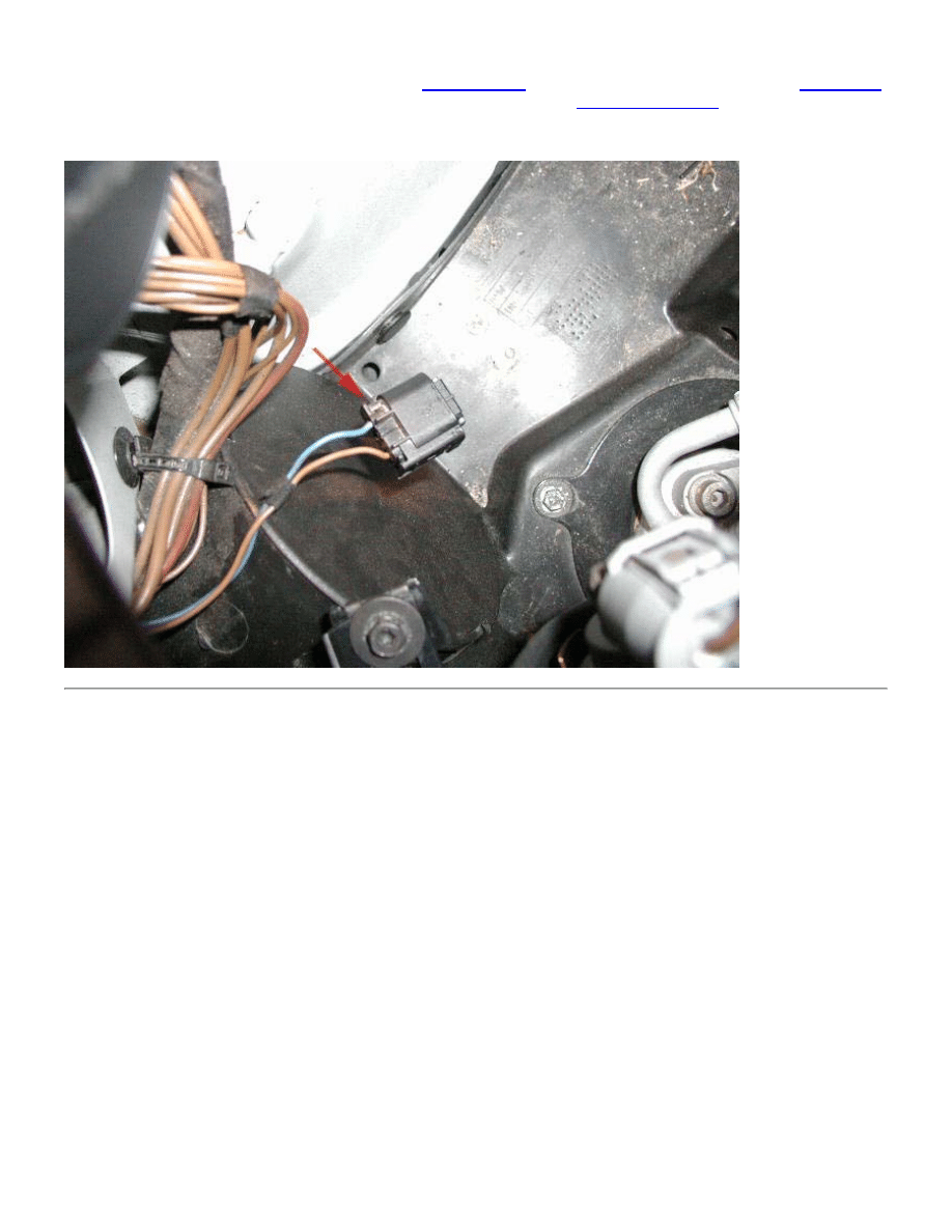
2 wires instead of 3. This poses a major hurdle since the Y-harness won't sen d a 12V signal to the new CELIS
parking light halo rings. I'd suggest you check on
BMWTips.com
(no solution posted so far) or ask the
bimmer.org
board for assistance as I haven't heard of an implemented solution yet.
Scroll to the bottom
for some untested
"hypothetical" solutions. If you find an answer, please e-mail me so I can ad the info to this site. Here's a picture of
the unique stock wiring.
8. Hook-up all the appropriate wires and carefully slide the assembly in place, but with more of a "straight ahead"
motion than the previous "rotating" motion. Protect the bumper while installing the assembly. Secure with the (4)
original screws, using the ratchet and magnetic pickup-tool as necessary. Her e are pics of the completed
driver-side assembly. Since this is a Halogen to Xenon upgrade, I don't have the self-leveling connector (see red
arrow) to plug in. I plan to wire in the manual adjustment knob harness somet ime down the road. (Thx Tyrone!)
8 of 12
9. On most OEM Halogen E39's, the switch to CELIS will require the passenger- side A/C filler tube to be bent back
for clearance. I used a tube-bending tool to be absolutely safe. Carefully bending it straight back by hand has been
a simple and effective way of doing it for many folks, but be cautious not to break any part of the tubing, allowing
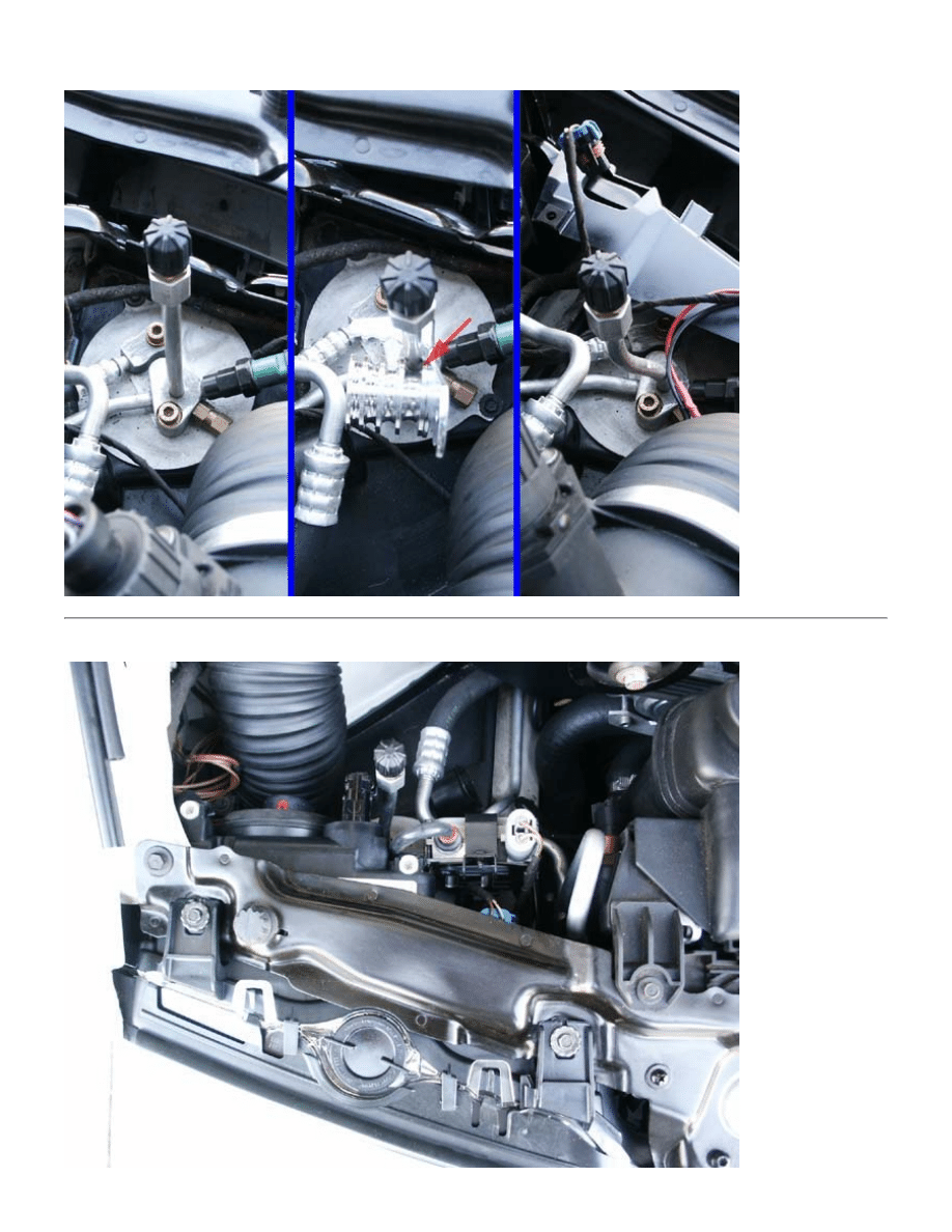
9 of 12
R134A to escape.
10. Here's are pics of the completed passenger-side assembly.
10 of 12
11. Check to see if the new assemblies line-up properly. The screw points hav e some play to allow them to be
moved around a bit. Check that all the bulbs work properly and have the head lights professionally aimed. If you
followed Step #2, you can get an approximate beam alignment using the masking tape lines and by turning the
assembly adjusters with the 6mm hex key.
11 of 12
10/11/2007 11:44 AM
Special notes for iT Wagon Owners with 2-wire plug issue
:
If you're good with car electronics or know a quality car stereo/alarm place you trust, here are some possible
options:
Tap the CELIS rings off the low beams.
Splice into your headlight wiring to power the CELIS rings. If you have Xenon lights, be sure to splice
into the line
prior
to the ballast.
Plug or adapt the existing wiring into the blinker only. This causes the blinker to act exactly as
previously intended, dimly lit with the parking lights and brightly flashing with the blinkers.
Pros: CELIS rings light with the low beams and simple hookup.
Cons: Must splice into OEM wiring.
What is non-OEM: CELIS rings don't light with the parking lights. Blinkers will be dimly lit with parking
lights.
1.
Tap the CELIS rings off the fog lights.
Splice into your fog light wiring to power the CELIS rings.
Plug or adapt the existing wiring into the blinker only. This causes the blinker to act exactly as
previously intended, dimly lit with the parking lights and brightly flashing with the blinkers.
Pros: CELIS rings light with the fog lights and simple hookup.
Cons: Must splice into OEM wiring.
What is non-OEM: CELIS rings don't light with the parking lights. Blinkers will be dimly lit with parking
lights. Fog lights must be on at all times to light the CELIS rings.
2.
OEM-like solution, but difficult.
Find 2 types of durable 12V relays that are tested so one triggers at the low er "parking light" voltage
and the other triggers at the higher "blinker" voltage (probably 12V) of the OEM wiring harness. Find
and cleanly tap a properly-fused 12V power lead into the engine compartment to feed the
switched-circuit portion of the relays. The low voltage trigger relay should be wired to send 12V to the
CELIS rings when the parking lights are on and the high voltage trigger relay wired to flash the blinkers
as needed. A setup using 2 relays total could power both sides, but I think building separate dual-relay
packs for each side would be cleaner and possibly avoid light bulb Check Control system issues.
Pros: I believe this will work exactly as an OEM CELIS setup. Using the wirin g plug adapters, this could
be a "plug in" solution instead of splicing into the OEM wiring.
Cons: Must find the lower trigger voltage relay, if it even exists and build/mount weather-proof relay
3.

12 of 12
10/11/2007 11:44 AM
packs. Must cleanly tap 12V from an appropriate power source.
OEM-like solution, but difficult and untested.
Find durable 12V relays that are tested to trigger at the lower "parking ligh t" voltage. Find and cleanly
tap a properly-fused 12V power lead into the engine compartment to feed the switched-circuit portion
of the relays. The trigger relay should be wired to send 12V to the CELIS rings when the parking lights
are on. A setup using 1 relay total could power both sides, but I think building separate relay packs for
each side would be cleaner and possibly avoid light bulb Check Control system issues.
Tap the turn signal blinkers off the sidemarker bulbs so they blink together. I'm unsure how difficult it
is to splice into the sidemarker bulbs, if there's sufficient voltage to power both sets of bulbs, and how
it might adversely affect the light bulb Check Control system. Definitely proceed at your own risk.
Pros: I believe this will work exactly as an OEM CELIS setup.
Cons: Must find the lower trigger voltage relay, if it even exists and build/mount weather-proof relay
packs. Must cleanly tap 12V from an appropriate power source. Must splice int o OEM wiring. Shared
power concerns. Light Check Control system affect is unknown.
4.
Close to OEM-like solution.
Find durable 12V relays that are tested they trigger at the lower "parking light" voltage. Find and
cleanly tap a properly-fused 12V power lead into the engine compartment to feed the switched-circuit
portion of the relays. The trigger relay should be wired to send 12V to the CELIS rings when the
parking lights are on. A setup using 1 relay total could power both sides, but I think building separate
relay packs for each side would be cleaner and possibly avoid light bulb Check Control system issues.
Plug or adapt the existing wiring into the blinker only. This causes the blinker to act exactly as
previously intended, dimly lit with the parking lights and brightly flashing with the blinkers.
Pros: The CELIS rings will light with the parking lights and independent of the low beams or fog lights.
Using the wiring plug adapters, this could be a "plug in" solution instead of splicing into the OEM
wiring.
Cons: Must find the lower trigger voltage relay, if it even exists and build/mount weather-proof relay
packs. Must cleanly tap 12V from an appropriate power source.
What is non-OEM: Blinkers will be dimly lit with parking lights.
5.
Challenges with the above solutions:
Must be comfortable with basic car electrical principles.
Where to cleanly and safely tap 12V in or into the engine compartment
Build relay packs that are weather-proof, won't overheat/fail, and look/mount in an OEM fashion.
Use OEM-type wire plugs to keep everything fairly stock in appearance.
Optimized for 800x600 or higher resolution.
Copyright © Midnight Designs, 2004. All Rights Reserved. All images and registered trademarks are used to benefit and without i ntent to infringe
on the holder. Contents Subject to Change Without Notice.
Wyszukiwarka
Podobne podstrony:
BMW e39 Demontaż reflektora
bmw E39 awaria reflektorow ksenonowych
bmw E39 E46 E53 nie dziala dmuchawa
Instalacja modułu Bluetooth w BMW E39
TEST KONSOLI ZEGARA, BMW E39 PDFy
Lusterko wsteczne z kompasem do BMW E39
Komputer pokładowy instalacja w BMW E39
bmw E39 samoczynne dizalanie centralnego zamka
Akcesoria multimedialne do BMW E39(1)
bmw E39 brak mocy w modelach do 01 11 02
Złącze AUX w BMW E39(1)
BMW E39 Wymiana wężyków spryskiwaczy
bmw E39 E53 nie dziala dmuchawa
Zmieniarka CD w BMW E39
bmw E39 cieple powietrze na nogi z klimatyzacji
bmw E39 E46 E53 nie dziala dmuchawa
Instalacja modułu Bluetooth w BMW E39
TEST KONSOLI ZEGARA, BMW E39 PDFy
więcej podobnych podstron