Fitting Instructions / Inbouwinstructie / Manuel d’
Fitting Instructions / Inbouwinstructie / Manuel d’
Instruction
Instruction
SGI
SGI
683010*0
1/ 11
21-03-2002
Instruction number / Instructienummer / Numero d’instruction:683010
Car type / Auto type / Automobile type:
Nissan Almera 1.5 16V
Year of construction / Bouwjaar / Année de fabrication
02-
Engine code / Motorcode / Numero du moteur:
QG15
Injection system / Injectiesysteem / Injection systeme:
Nissan Motors
Kitnumbers / Setnummers / Numeros du set:
693010
English
These fitting instructions only contain specific information about this type of car. For further information always refer to the “AG
Dealer Information” binder.
Always check the system for leakage after filling up the LPG tank.
All electrical connections must be made with the supplied connectors or be soldered and finished with heatshrink.
The given measures and threadcolors in this instruction, should always be checked and measured in case of occurring
changes in the cars wiring and possible changes in type of vehicle.
The measures used in this manual are, if not mentioned specificly, given in mm’s.
Always use an anti-corrosion coating where necessary to prevent rust.
Note: This manual is based on dutch regulations. It is the installer’s responsibility to check the local regulations
and to make all neccesary adaptions!
Nederlands
Deze inbouwinstructie vermeldt alleen de specifieke informatie voor dit type auto. Voor verdere informatie moet altijd de
“Dealer informatie map” geraadpleegd worden.
Controleer na het tanken de gehele installatie op eventuele lekkage.
Electrische verbindingen moeten gemaakt worden met de daarvoor bijgeleverde connectoren of d.m.v. solderen en afwerken
met krimpkous.
De in deze instructie aangegeven maten en draadkleuren dienen zelf opgemeten en gecontroleerd te worden i.v.m. onderlinge
verschillen in de auto’s en mogelijke wijzigingen in de bedrading.
De in deze instructie gebruikte maten worden, indien niet nader vermeld, weergegeven in mm’s.
Behandel na de inbouw de door de inbouw ontstane korrosiegevoelige plaatsen altijd met een korrosiewerend middel.
Opmerking:Deze instructie is gebaseerd op de Nederlandse inbouweisen.Het is de verantwoordelijkheid van de inbouwer om
de lokale regels te controleren en alle nodige aanpassingen uit te voeren!
France
Cette manuel d’instruction signale uniquement les informations spécifiques pour ce type de voiture. Pour dáutres informations,
il faudrait systématiquement consulter le “classeur Dealer-information”.
Après avoir fait le plein, contrôlez toute l'installation en vue d'une fuite éventuelle à l'aide d'une bombe de recherche de fuite ou
d'un détecteur de gaz.
Les connections électriques devraient être réalisées avec les connecteurs fournis ou à l'aide de soudures et terminées avec
gaine rétractable.
Les mesures et couleurs des fils indiqués dans cette instruction sont à mesurer ou contrôler par soi-même en raison des varia-
tions entre les différentes voitures et des possibles modifications des câblages.
Traitez tous les trous de perçage avec un antirouille.
Toutes les dimensions sont données en milimètres sauf indication contraire.
Attention:Cette manuel d’instruction ets bassé sur normes néerlandais. C’est la responsabilité du mechanicien pour controller
les normes localement!
Fitting Instructions / Inbouwinstructie / Manuel d’
Fitting Instructions / Inbouwinstructie / Manuel d’
Instruction
Instruction
SGI
SGI
683010*0
2/ 11
21-03-2002
LPG switch
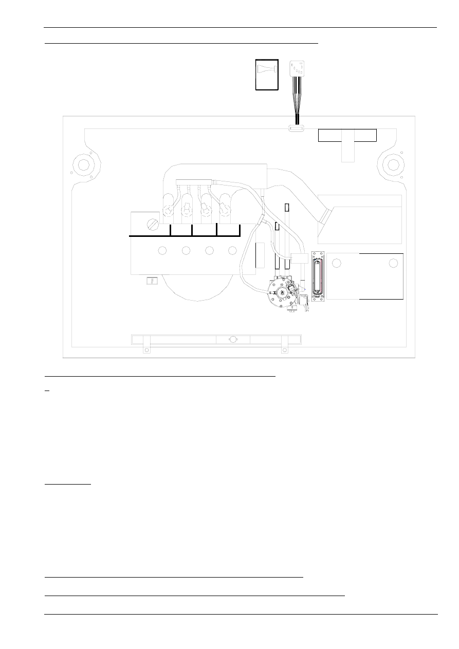
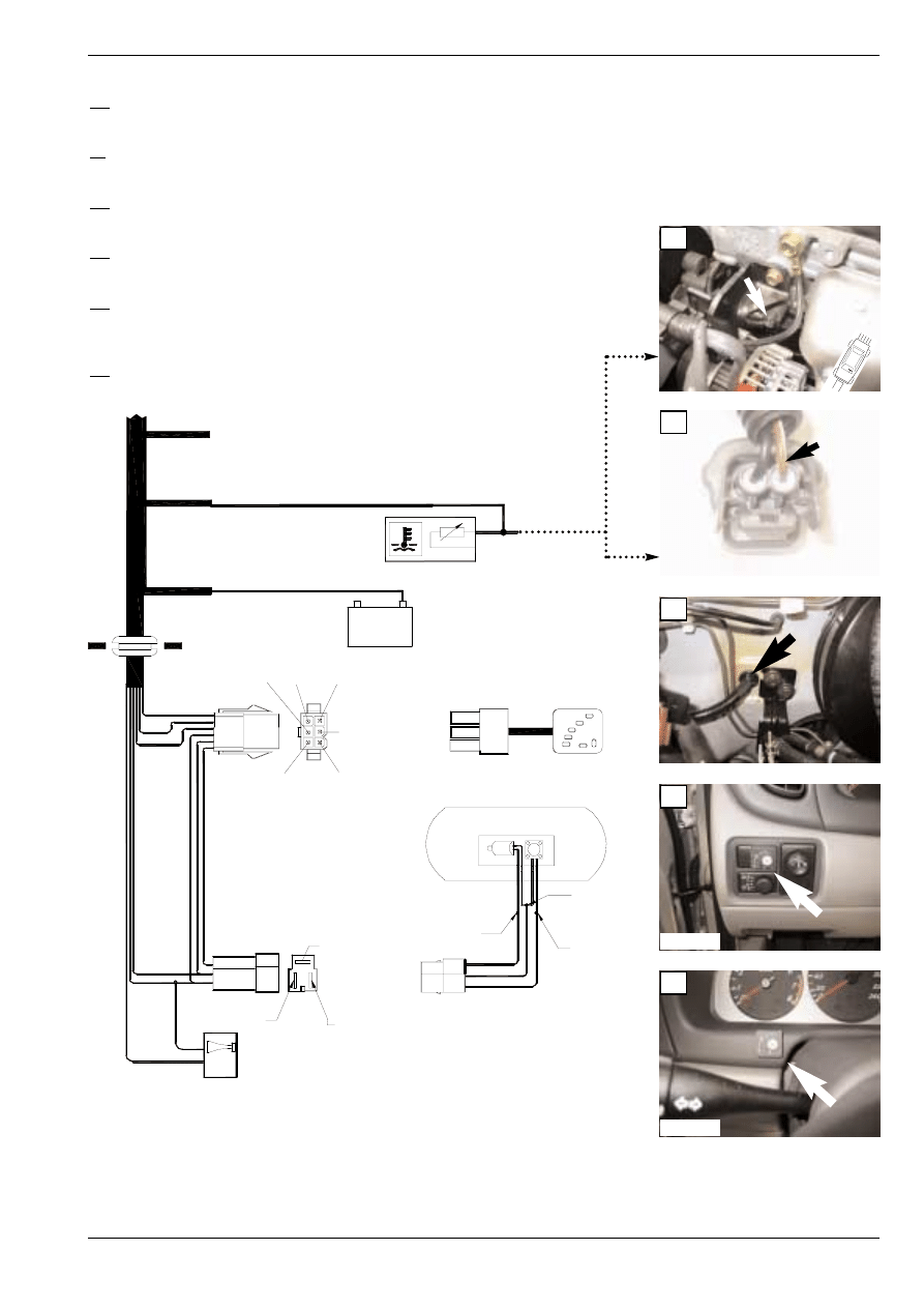
Overview system / Systeem overzicht / Implantation Générale
Fitting order / Montage volgorde / Ordre de montage
Nr.:
Description / Omschrijving / Description:
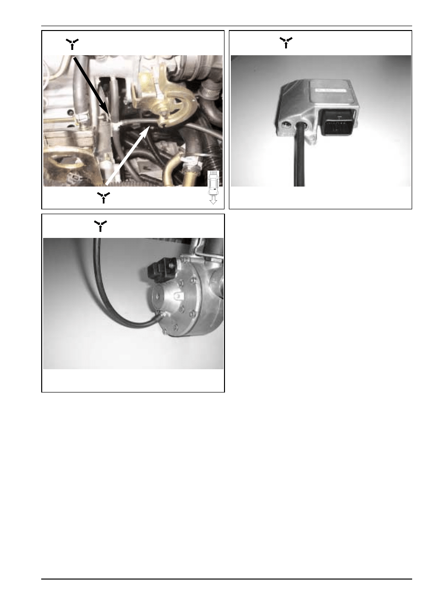
1.
Vaporiser / Verdamper / Vaporiseur
2.
Waterconnections / Wateraansluitingen / Connections d` eau
3.
Vacuumnipple / Vacuümnippel / Nipple à dépression
4.(17).
Grummet / Doorvoerrubber / Passe fil caoutchouc
5.
SGI-injectors / SGI-injectoren / Injecteurs SGI
6.
Fuel rail LPG / Fuel rail LPG / Common rail GPL
7.0.
SGI-computer / SGI-computer / Calculateur SGI
7.1.
Interface unit / Interface unit / Unit d’ interface
8.
Vacuumhoseconnections / Vacuümslangaansluitingen / Connections de tuyau à dépression
9,10,11,13,14 :
Mount connectors to the components / Monteer connectoren op de componenten /
Monter les connecteurs aux composants
12.
Petrol injector interruptions / Benzine injector onderbrekingen / Coupure injecteurs d’ essence
15.
Temperature signal / Temperatuur signaal / Signal de temperature
16.
Ground / Massa / Masse
17.(4)
Grummet / Doorvoerrubber / Passe fil caoutchouc
18.
Switch / Schakelaar / Interrupteur
19.
Connections to LPG switch / Aansluitingen LPG schakelaar / Connections vers l’ interrupteur
20.
Beeper / Alarm / Alarme sonore
Explanation of symbols / Beschrijving symbolen / Définition symboles
Manual AG Pulse-switch / Handleiding AG Pulse-switch / Manuel AG Pulse-switch
16
1
2
3
4 (17)
5.0
6
12
7.0
7.1
8
19
20
18
15
Fitting Instructions / Inbouwinstructie / Manuel d’
Fitting Instructions / Inbouwinstructie / Manuel d’
Instruction
Instruction
SGI
SGI
683010*0
3/ 11
21-03-2002
1A
1C
1E
1F
1D
1B
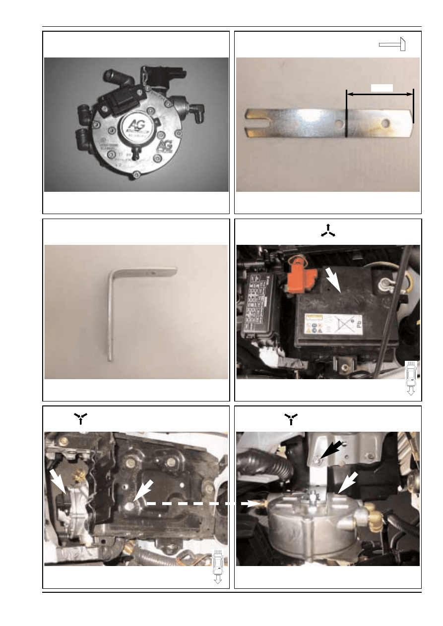
70 mm
AG 50151
AG 50151 + AG 600001
AG 50151 + AG 600001
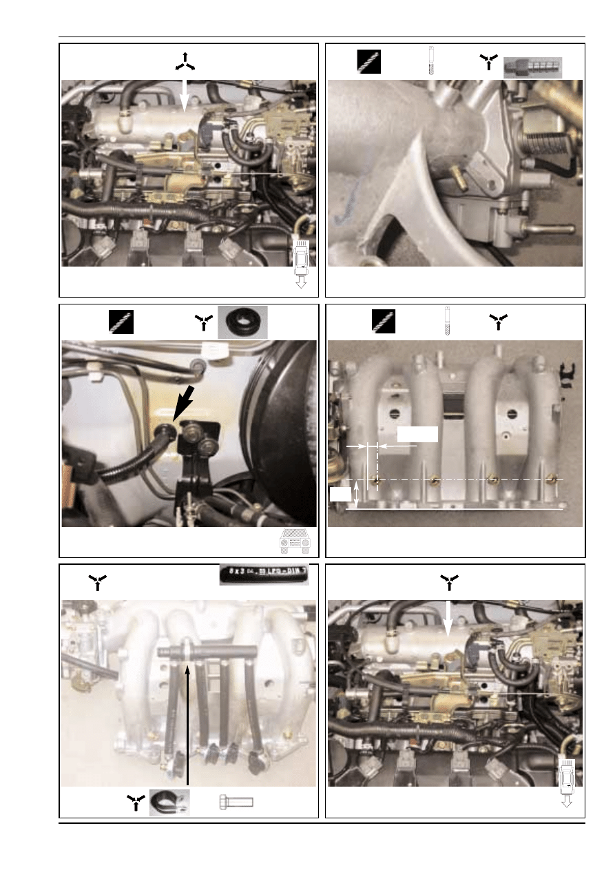
Preparation of vaporiser
Voorbereiding van verdamper
Préparation du vaporiseur
Preparation of 50151
Voorbereiding van 50151
Préparation du 50151
Fitting Instructions / Inbouwinstructie / Manuel d’
Fitting Instructions / Inbouwinstructie / Manuel d’
Instruction
Instruction
SGI
SGI
683010*0
4/ 11
21-03-2002
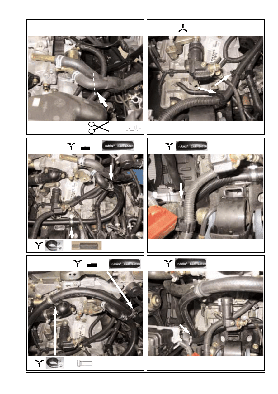
2A
2C
2E
2F
2D
2B
16-16mm
16-16mm
+
+
+
2x
+M 6
Fitting Instructions / Inbouwinstructie / Manuel d’
Fitting Instructions / Inbouwinstructie / Manuel d’
Instruction
Instruction
SGI
SGI
683010*0
5/ 11
21-03-2002
3A
4A(17)
5B
5C
5A
3B
Ø 11 mm
Ø 5mm
M6 x 1
AG 35303
Ø 5mm
Ø 9mm
Ø 13mm
M14x1
AG 600080
4X
AG 600090 + 4x 600050 +
L = 180mm
+M 8
11(4x)
45
Fitting Instructions / Inbouwinstructie / Manuel d’
Fitting Instructions / Inbouwinstructie / Manuel d’
Instruction
Instruction
SGI
SGI
683010*0
6/ 11
21-03-2002
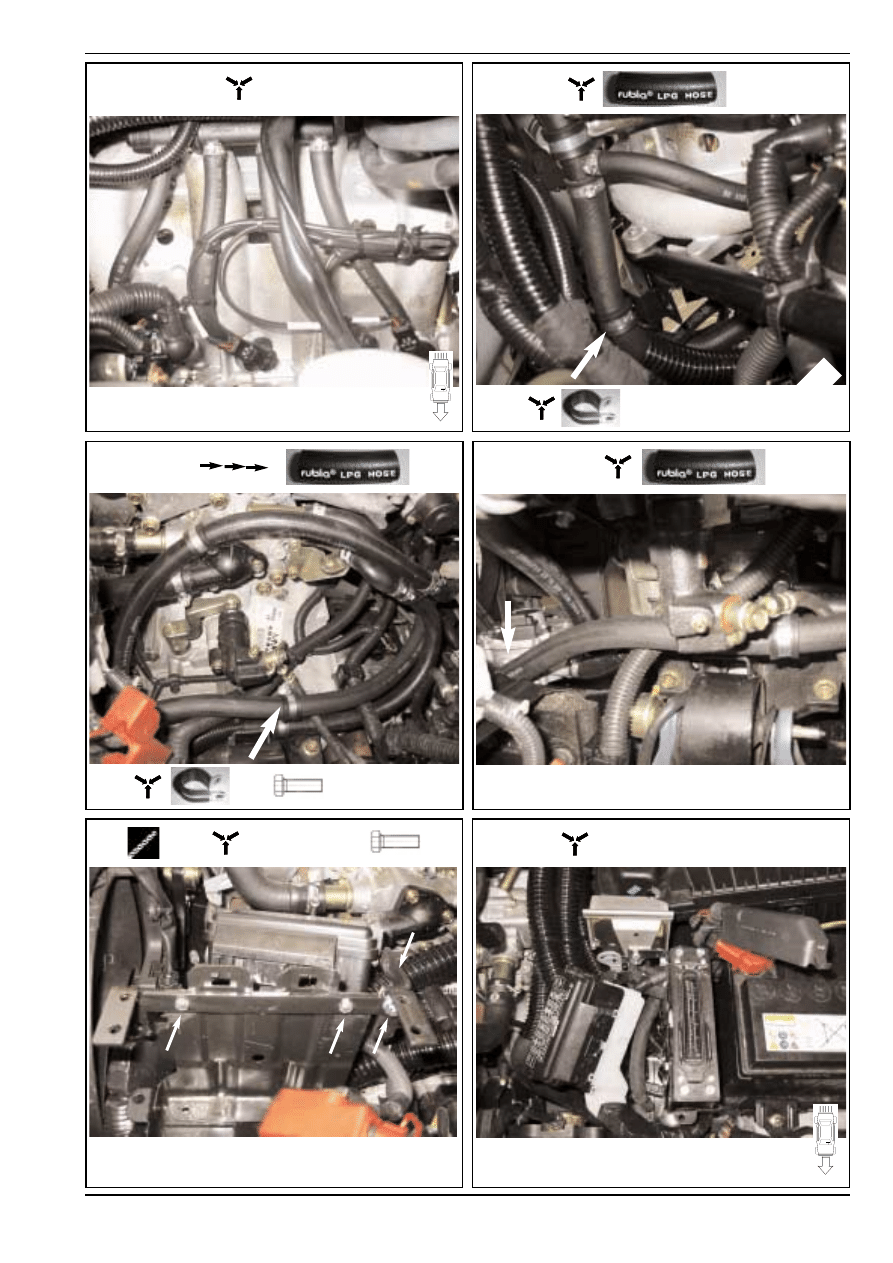
5D
6B
6C
6A
7A
7B
+M 6
AG 600100 + AG 600130
AG 202001 +
202000 + 3x M6
Ø 6
4x AG 600050
Fitting Instructions / Inbouwinstructie / Manuel d’
Fitting Instructions / Inbouwinstructie / Manuel d’
Instruction
Instruction
SGI
SGI
683010*0
7/ 11
21-03-2002
8A
8C
8B
Vacuümhose ø 5 mm
Vacuümslang ø 5 mm
Tuyau de depression ø 5 mm
Vacuümhose ø 3,2 mm
Vacuümslang ø 3,2 mm
Tuyau de depression ø 3.,2 mm
Vacuümhose ø 3,2 mm
Vacuümslang ø 3,2 mm
Tuyau de depression ø 3,2 mm
Vacuümhose ø 5 mm
Vacuümslang ø 5 mm
Tuyau de depression ø 5 mm
+T
6-4-6 mm
Fitting Instructions / Inbouwinstructie / Manuel d’
Fitting Instructions / Inbouwinstructie / Manuel d’
Instruction
Instruction
SGI
SGI
683010*0
8/ 11
21-03-2002
3H Red/White (+15)
Injector 2
Purple = 21
Black = 10
Injector 4
Black = 18
Purple = 34
Yellow = 31
Injector 3
Injector 2
+
-
+
-
Injector 4
Injector 3
-
+
+
-
D2 Black
C2 Black
C1 Red
E2 Black
E1 Red
D1 Red
23
6
Injector 1
19
1
5
4
3
2
21
20
22
32
Black
= 18
= 4
Brown
Red
= 2
10
9
7 8
25
24
27
26
12
14
13
11
30
28 29
31
16
15
18
17
34
33
35
Injector 1
-
+
F2 Black
F1 Red
E
1
A
B
C
D
2
3
4
H
F
G
Black 4H (GRND)
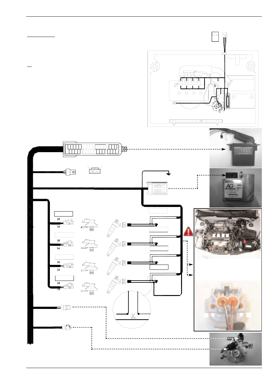
9,10,11,13+14:
Mount the connectors to the components
Monteer de connectors op de componenten
Monter les connecteurs aux composants
12
Petrol injector interruptions
Benzine injector onderbrekingen
Coupure injecteurs d’essence
15 to 20 See next page
15 t/m 20 Zie volgende pagina
15 à 20 : Page suivante
DIAGNOSIS
DIAGNOSE
DIAGNOSTIC
Electrical connections / Electrische aansluitingen / Raccordement électrique
LPG switch
No.1 Red / Black
No.1 Yellow/Black
No.1 Blue/Black
No.2 Black/Red
No.1 Green/Black
9
11
13
14
12
10
Cylinder arrangement / Cilindernummering
Numérotage de cylindre
Position of interruption / Plaats van onder-
breking / Position du déconnection
16
17(4)
14
13
1
1
2
2 3 4
12
18
15
20
19
10
9
11
+
-
Fitting Instructions / Inbouwinstructie / Manuel d’
Fitting Instructions / Inbouwinstructie / Manuel d’
Instruction
Instruction
SGI
SGI
683010*0
9/ 11
21-03-2002
GRND - (31)
Black = 18
1. Red = 35 Contact (+15)
7.
4.
5.
6.
7. Blue = 17 Beeper
5.
4.
6.
2.
3.
1.
4. Black = 18 GRND -
5. Purple = 34 LPG+
6. Yellow Level
3. Brown = 6 Pulse
2. Orange = 1 Diagnose led
1.
5.
2.
6.
3.
4.
+
Yellow to yellow
Red to purple
6.
5.
Black to black
-
Black/White = 24
Red = 12
Black = 25
Temperature sensor
15:
Temperature sensor / Temperatuursensor / Capteur de température
16
Ground / Massa / Terre
17:
Grummet / Doorvoerrubber / Passe fils caoutchouc
18:
LPG switch / LPG schakelaar / Interrupteur GPL
19:
Connections to LPG switch + LPG tank / Aansluitingen schakelaar+ LPG tank /
Connections vers l’interrupteur GPL+ réservoir GPL
20:
Beeper / Alarm / Alarme sonore
Electrical connections / Electrische aansluitingen / Raccordement électrique
15
16
17 (4)
18
19
20
Brown/White
Optional
15
15
17
18
18
Option 1
Option 2
Fitting Instructions / Inbouwinstructie / Manuel d’
Fitting Instructions / Inbouwinstructie / Manuel d’
Instruction
Instruction
SGI
SGI
683010*0
10/ 11
21-03-2002
Y
16-16-16mm
T
16-16-16mm
16-20mm
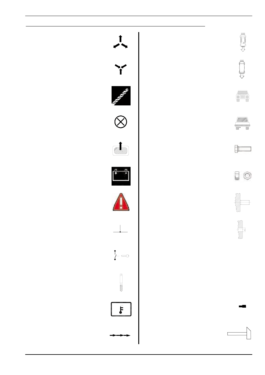
Disassemble part
Demonteer onderdeel
Démonter élément
Mount part
Monteer onderdeel
Monter élément
Drill
Boren
Percer
Redundant part
Te vervallen onderdeel
Pièce technique d’origine à supprimer
Piece to be removed from element
Te verwijderen gedeelte van onderdeel
Partie d’origine à supprimer
Battery
Accu
Batterie
Warning
Let op
Fais attention
Solder connection / Crimp connection
Soldeerverbinding / Krimpverbinding
Connection à souder / Connection à sertir
Ignition
Contactslot
Contact moteur
Screw tap
Draadtap
Tarauder
Temperature sensor / signal
Temperatuur sensor / signaal
Capteur / Signal de temperature
Pierce
Doorvoeren
Guider
View from top
Bovenaanzicht
Vue d’ en haut
View from bottom
Onderaanzicht
Vue d’ en bas
Frontview
Vooraanzicht
Aspect frontal
Rearview
Achteraanzicht
Aspect arrière
Bolt
Bout
Boulon
Nut
Moer
Écrou
Existing threadend
Bestaand draadeind
Boulon fileté d’origine
Existing threadhole
Bestaand draadgat
Trou taraudé d’origine
Water / Vacuum T-joint
Water / Vacuüm T-stuk
Raccord en T d’ eau / depression
Water / Vacuum Y-joint
Water / Y-stuk
Raccord en Y
Waterpipe
Waterpijpje
Raccord d’ eau
Edit bottom / Part
Bewerk bodem / Onderdeel
Adaptez fond / Pièce
Explanation of symbols / Beschrijving symbolen / Définition symboles
Fitting Instructions / Inbouwinstructie / Manuel d’
Fitting Instructions / Inbouwinstructie / Manuel d’
Instruction
Instruction
SGI
SGI
683010*0
11/ 11
21-03-2002
In combination with the Sequential Gas Injection (SGI) system of AG Autogas Systems a so-called pulse switch is supplied. Because the oper-
ation of this switch differs from that of the traditional switch, a description of the pulse switch is included.
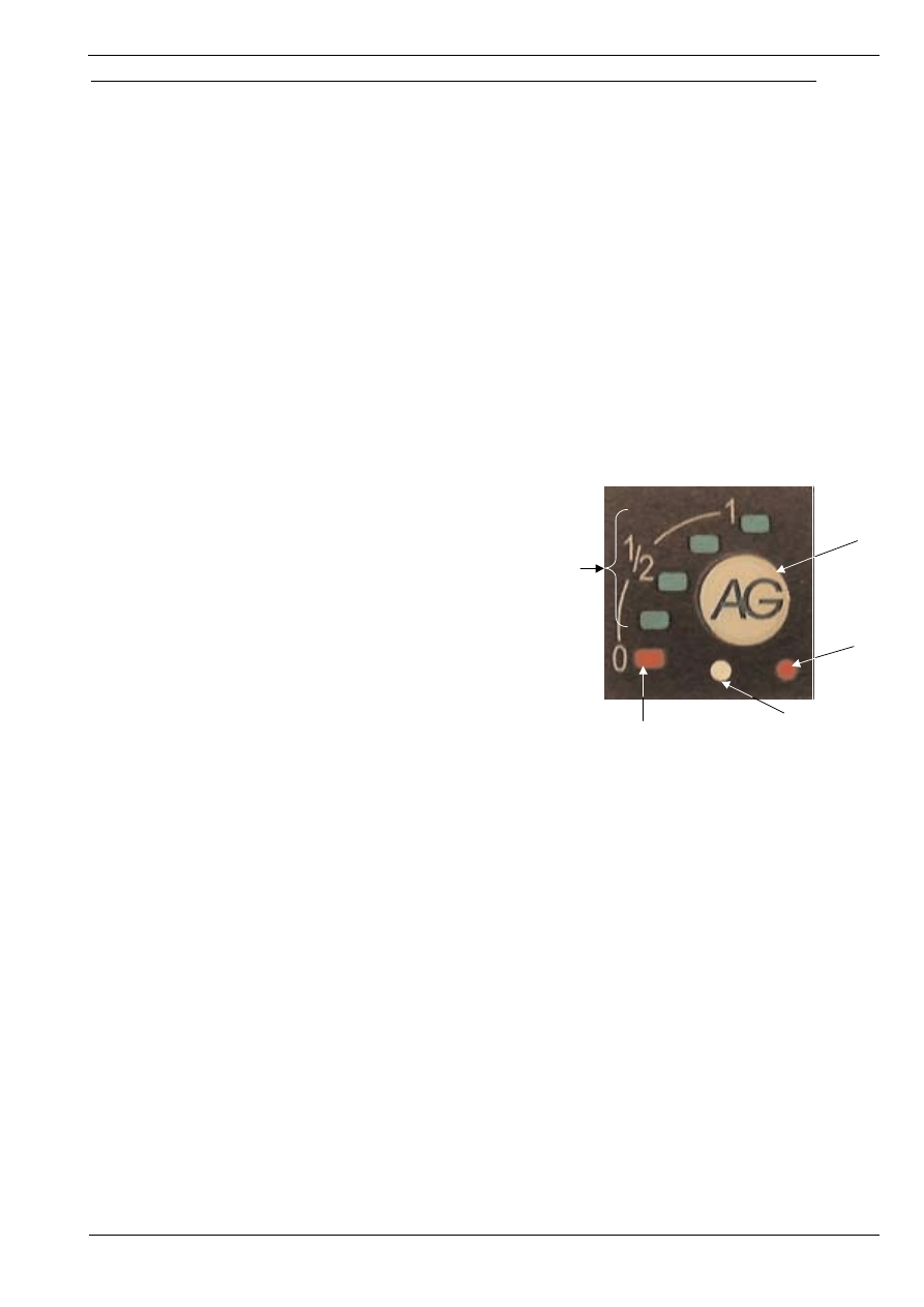
The photograph below shows the front of the pulse switch, which can be seen on the dashboard.
The photograph shows that the switch is supplied with a number of functions.
A is the switch itself. It is used to switch from LPG to petrol. When turning the ignition on the switch automatically takes the last-used position.
At low temperatures, however, the engine will run on petrol for a short time, before actually switching over to LPG. In this case the LPG shut-
off valves are opened first, with the engine still running on petrol (flushing). In this condition the tank-indicator lights (B and C) will light up or
will start flashing, together with the diagnosis LED (E). Soon after the supply lines have been filled with LPG in this way, the SGI injectors
open, thus realising a smooth switch-over. Because this is a pulse switch, a light touch will do to switch over between petrol and LPG. When
the car runs on petrol, no LED will be lit or be flashing.
B and C are the LEDs that indicate the LPG level. The LEDs light up the moment the LPG shut-off valves are being fed. When the LPG tank
is full, all four green LEDs (C) will be lit (when driving on LPG). The emptier the LPG tank gets, the more LEDs will go out from top to bottom.
When the last green LED has gone out, the red LED (B) will light up, to indicate that no more than a limited distance can be driven on LPG.
When the SGI computer detects an empty tank it automatically switches over to petrol. This is indicated by a pulsating, audible signal.
D is not an indicator light, but a photocell which adjusts the display intensity of the LEDs B and C to the light intensity of the environment.
During the day, with the sun shining, the LEDs will be illuminated more brightly than in the evening.
E is the diagnosis indication. This red LED starts flashing when the SGI computer recognises the LPG position, while the car is still running on
petrol (e.g. when the engine temperatures are too low or when the LPG tank is empty (in this case together with an audible signal)). When a
fault is being detected while driving on LPG, the red LED will also start flashing as an indication for the driver to contact the dealer, who will
correct the fault.
....................................................................................................................................................................................................................................
In combinatie met het Sequeniële Gas Injectie (SGI) systeem van AG Autogas Systems wordt een puls schakelaar geleverd. Aangezien de
werking van deze schakelaar verschilt van de traditionele schakelaar, vindt u hierin een beschrijving van de werking van de zgn. pulse-switch.
Op de onderstaande foto staat een afbeelding van het frontje van de pulse-switch, zoals deze zichtbaar is op het dashboard.
Hierop is te zien, dat de schakelaar onder andere voorzien is van een aantal funkties.
A is de schakelaar zelf, waarmee overgeschakeld kan worden van LPG naar ben-
zine. Deze zal na het op kontakt zetten automatisch de laatst gebruikte stand aan-
nemen. Bij lage motortemperaturen zal de motor echter een aantal minuten op
benzine draaien alvorens daadwerkelijk overgeschakeld wordt op LPG. Hierbij wor-
den eerst de LPG afsluiters geopend, terwijl de motor nog op benzine draait
(“flushen”). In deze situatie zal de tankindicatie (B en C) tezamen met de diag-
noseled (E) branden resp. knipperen. Wanneer de aanvoerslangen op deze manier
gevuld zijn met LPG, openen de SGI injectoren kort daarna, waardoor een
vloeiende overname wordt gerealiseerd. Aangezien dit een pulse-switch is, is een
korte aanraking voldoende om over te kunnen schakelen tussen benzine en LPG.
B en C zijn de LED's, waarmee een indicatie wordt gegeven van de LPG tankin-
houd. Bij een volle LPG tank zullen alle vier de groene LED's (C) branden wanneer
op LPG gereden wordt. Gedurende het leegraken van de LPG tank zullen van
boven naar beneden de LED's doven. Bij het doven van de laatste groene LED
gaat de rode LED (B) branden, als teken dat nog een beperkte afstand op LPG
afgelegd kan worden.
Indien de SGI-computer een lege tank detecteert, zal deze automatisch
terugschakelen naar benzine, hetgeen gepaard gaat met een pulserend akoestisch signaal.
D is geen indicatie, maar een fotocel, welke ervoor zorgt, dat de weergave van de indicatie LED's B en C afhankelijk is van de lichtsterkte van
de omgeving; bij zonlicht zullen de LED's feller oplichten dan 's avonds.
E is de diagnose indicatie. Deze rode LED zal knipperen als de SGI computer de LPG stand herkent, terwijl de motor nog op benzine draait
(bijvoorbeeld bij te lage motortemperatuur of bij een lege LPG tank (samen met een akoestisch signaal)). Indien een storing gedetecteerd
wordt tijdens het rijden op LPG, zal deze LED eveneens knipperen als teken voor de bestuurder om kontakt met de dealer op te nemen ten
einde de storing te laten oplossen.
....................................................................................................................................................................................................................................
Un 'interrupteur à pulsation' équipe le système d'injection séquentielle de gaz (Sequential Gas Injection, SGI) d'AG Autogas Systems. Etant
donné que le fonctionnement de cet interrupteur diffère de celui de l'interrupteur traditionnel, nous avons joint une description de cet interrup-
teur à pulsation.La photo ci-dessous montre l'avant de l'interrupteur à pulsation tel qu'il se présente sur le tableau de bord.
Cette photo indique que l'interrupteur dispose d'un certain nombre de fonctions.
A est l'interrupteur lui-même, utilisé pour passer du G.P.L. à l'essence. Quand on allume le contact, l'interrupteur se met automatiquement sur
la dernière position utilisée. Cependant, si le moteur est froid, il fonctionnera brièvement sur l'essence avant de passer vraiment au G.P.L.
Dans ce cas, les valves d'arrêt du G.P.L. sont d'abord ouvertes alors que le moteur fonctionne encore sur l'essence ("rinçage"). Dans cette sit-
uation, les voyants du réservoir (B et C) ainsi que le diode électroluminescent (DEL) de diagnostique (E) s'allument ou commencent à clignot-
er. Une fois que les conduites d'alimentation sont ainsi remplies de G.P.L., les injecteurs SGI s'ouvrent, ce qui permet un passage en douceur
d'un carburant à l'autre. Etant donné qu'il s'agit d'un interrupteur à pulsation, il suffit de l'effleurer légèrement pour passer de l'essence au
G.P.L. et inversement. Quand la voiture fonctionne à l'essence, aucun voyant ne s'allume ou ne clignote.
B et C sont les DEL qui indiquent le niveau de G.P.L. Les DEL s'allument dès que les valves d'arrêt G.P.L. sont alimentées. Quand le réservoir
de G.P.L. est plein (et que le moteur fonctionne sur G.P.L.), les quatre DEL verts (C) sont allumés. Au fur et à mesure que le réservoir de
G.P.L. se vide, le nombre de DELallumés diminue de haut en bas. Quand le dernier DELvert s'éteint, le DELrouge (B) s'allume pour indiquer
que le G.P.L. restant ne permet de parcourir qu'une distance limitée.
Quand le système électronique SGI détecte un réservoir vide, il passe automatiquement sur le réservoir d'essence, ce qui s'accompagne d'un
signal sonore intermittent.
D n'est pas un voyant indicateur, mais une cellule photoélectrique qui règle l'intensité de l'affichage des DEL B et C sur l'intensité lumineuse
ambiante. Pendant la journée, quand le soleil brille, les DELseront éclairés plus vivement que le soir.
E est l'indicateur de diagnostique. Ce DELrouge commence à clignoter quand le système électronique SGI identifie la position G.P.L., alors
que la voiture fonctionne encore sur essence (par exemple quand le moteur est trop froid ou quand le réservoir G.P.L. est vide [cela s'accom-
pagne d'un signal sonore]). Quand une erreur est détectée alors que le moteur fonctionne sur G.P.L., le DEL rouge se met également à clig-
noter pour indiquer au conducteur qu'il doit se rendre chez son concessionnaire pour remédier à ce problème.
Manual AG Pulse-switch / Handleiding AG Pulse-switch / Manuel AG Pulse-switch
A
E
D
B
C
Wyszukiwarka
Podobne podstrony:
nissan almera 18 16v
nissan almera 18 16v
akumulator do nissan almera hatchback ii n16 15 16v 18 16v 15
akumulator do nissan almera ii n16 15 16v 18 16v 15 dci
Nissan Almera2 1 5
Nissan Almera2 1 8
Cw8 9 15 16V, PBiMAS, Frątczak, PBIMAS, PBiMAS cw123, PBiMAS cw123, Materiały do ćwiczeń PBiMASI-cz.
Nissan Almera2 1 5
Nissan Almera 4 drzwiowy, typ N16, 1995 2007
akumulator do nissan almera ii n16 22 di
akumulator do mazda 323 s v ba 13 16v 15 16v
akumulator do kia rio kombi 13 15 16v
akumulator do daihatsu gran move g3 15 16v 16 16v
akumulator do mitsubishi lancer vii ckpa 13 12v gl glx 15 16v
Nissan Almera 3 drzwiowy, typ N16, 1995 2007
akumulator do suzuki sx4 hatchabck 15 i 16v 16 i 16v vvt 2w
akumulator do mazda demino a6 a7 12 13 16v 13 14 15 15 16v
akumulator do mitsubishi lancer vii coupe ckpa 15 16v 18 18 g
więcej podobnych podstron