©2003 VERTEX STANDARD CO., LTD. E089890A
Technical Supplement
Introduction
This manual provides technical information necessary
for servicing the Yaesu FT-100/-100D HF & V/UHF-Band
Transceiver. It does not include information on installa-
tion and operation, which are described in the FT-100/-
100D Operating Manual provided with the transceiver,
or on accessories which are described in their manuals.
The FT-100/-100D is carefully designed to allow the
knowledgeable operator to make nearly all adjustments
required for various station conditions, modes and oper-
ator preferences simply from the controls on the panels,
without opening the case of the transceiver. The FT-100/-
100D Operating Manual describes these adjustments, plus
certain internal settings.
Servicing this equipment requires expertise in handling
surface mount chip components. Attempts by unqualified
persons to service this equipment may result in perma-
nent damage not covered by warranty. For the major cir-
cuit boards, each side of the board is identified by the type
of the majority of components installed on that side. In
most cases one side has only chip components, and the
other has either a mixture of both chip and lead compo-
nents (trimmers, coils, electrolytic capacitors, packaged
ICs, etc.), or lead components only.
While we believe the technical information in this man-
ual is correct, VERTEX STANDARD assumes no liability
for damage that may occur as a result of typographical or
other errors that may be present. Your cooperation in
pointing out any inconsistencies in the technical informa-
tion would be appreciated. VERTEX STANDARD reserves
the right to make changes in this transceiver and the align-
ment procedures, in the interest of technological improve-
ment, without notification of owners.
Contents
Specification................................................... 2
Exploded View & Miscellaneous Parts..... 3
Alignment ....................................................... 5
Block Diagram ............................................. 17
Interconnection Diagram........................... 18
Board Unit (Schematics, Layouts & Parts)
LOCAL Unit ........................................................... 63
REF Unit ................................................................. 75
PA Unit ................................................................... 77
LPF Unit.................................................................. 89
DISPLAY Unit........................................................ 99
CNTL Unit ............................................................ 107
CONNECT-1 Unit ............................................... 117
VR Unit ................................................................. 118
CONNECT-2 Unit ............................................... 119
Option ......................................................... 120
S EP
VFO/MR
PWR
HOME
LOCK
DSP
FUNC
DWN
U P
MODE
D
C
B
A
C
C T
S
L
Q
A
L
R
R
S
E
E L
F
F
A
4-8-8 Nakameguro, Meguro-Ku, Tokyo 153-8644, Japan
US Headquarters
10900 Walker Street, Cypress, CA 90630, U.S A.
International Division
8350 N.W. 52nd Terrace, Suite 201, Miami, FL 33166, U.S.A.
P.O. Box 75525, 1118 ZN Schiphol, The Netherlands
YAESU UK LTD.
Unit 12, Sun Valley Business Park, Winnall Close
Winchester, Hampshire, SO23 0LB, U.K.
VERTEX STANDARD HK LTD.
Unit 5, 20/F., Seaview Centre, 139-141 Hoi Bun Road,
Kwun Tong, Kowloon, Hong Kong

2
Specifications
General
Frequency Range:
Receive 100 kHz – 970 MHz (European version)
100 kHz – 824 MHz, 849 – 864 MHz,
and 894 – 961 MHz (U.S.A version)
Transmit 160 – 6 Meters
2 Meters
70 Centimeters (Amateur bands only)
5167.5 kHz: Alaska Emergency Frequency
(U.S.A. version only)
Emission Modes:
A1 (CW), A3 (AM), A3J (LSB/USB),
F1 (9600 bps Packet), F2 (1200 bps Packet), F3 (FM)
Synthesizer Steps (Min.):
1.25 Hz (CW/SSB), 100 Hz (AM), 100 Hz (FM),
1 kHz (FM)
Antenna Impedance:
50W, Unbalanced
Operating Temp. Range:
–10 °C to +60 °C (14 °F to 122 °F)
Frequency Stability:
Better than ±4 ppm (–10 °C to +50 °C) (SSB/CW/AM)
Better than ±{1 kHz +4 ppm} (FM)
Power Requirements:
DC 13.8V ± 10%, Negative Ground
Current Consumption:
Receive (Squelched): 1.2A, Receive (Max. Audio): 1.6A
Transmit: 22A (@ 100W RF output)
Case Size:
160(W) x 54(H) x 205(D) mm (6.3” x 2.2” x 8.0” WHD)
Weight:
3 kg. (6.6 lb.)
Transmitter
Power Output:
160 – 6m:100 Watts (25 Watts AM carrier)
2m:
50 Watts (12.5 Watts AM carrier)
70cm:
20 Watts (5 Watts AM carrier)
Modulation Types:
SSB: Balanced Modulator
FM: Variable Reactance
AM: Early Stage (Low Level)
FM Maximum Deviation:
±5 kHz (±2.5 kHz on FM-N)
Spurious Radiation:
Harmonics:
At least 40 dB down (1.8 – 29.7 MHz)
At least 60 dB down (50/144/430 MHz)
Non-harmonic: At least 50 dB down (1.8 – 29.7 MHz)
At least 60 dB down (50/144/430 MHz)
Carrier Suppression:
At least 40 dB
Opp. Sideband Suppression:
At least 50 dB
SSB Frequency Response:
400 Hz – 2600 Hz (–6 dB)
Microphone Impedance:
200W – 10kW (Supplied microphone: 2kW)
Receiver
Sensitivity:
SSB/CW
AM-N
FM
100 kHz – 150 kHz:
–
–
–
150 kHz – 250 kHz*: 5 µV
40 µV
–
250 kHz – 1.8 MHz*: 4 µV
32 µV
–
1.8 – 28 MHz*:
0.25 µV
2 µV
–
28 – 30 MHz:
0.25 µV
2 µV
0.50 µV
50 – 54 MHz:
0.20 µV
2 µV
0.50 µV
144/430 MHz:
0.125 µV
2 µV
0.20 µV
Above specifications are worst-case.
SSB/CW/AM-N figures are for 10 dB S/N, 12 dB SINAD
on FM. *: IPO off
Squelch Sensitivity:
SSB/CW/AM
FM
1.8 – 28 MHz:
2.5 µV
–
0.32 µV
0.20 µV
0.16 µV
68.985 MHz (SSB/CW/FM/Digital)
2nd IF: 11.705 MHz (SSB/CW/FM/Digital)
Better than 70 dB (1.8 – 30 MHz, 50 – 54 MHz)
Better than 60 dB (144 – 148 MHz, 430 – 440 MHz)
Better than 70 dB (1.8 – 30 MHz)
Better than 60 dB (50 – 54 MHz, 144 – 148 MHz,
430 – 440 MHz)
Selectivity (–6/–60 dB):
SSB/CW: 2.2 kHz/5.2 kHz
CW:
450 Hz/1.8 kHz
(FT-100: Optional XF-117C installed)
CW-N:
250 Hz/1.2 kHz
(Optional XF-117CN installed)
AM:
5.2 kHz/18 kHz
(Optional XF-117A installed)
FM:
15 kHz /25 kHz (–6/–50 dB)
Audio Output:
At least 1.5W into 8
W
@ 10% THD
Audio output impedance:
4
W
– 8
W
Specifications are subject to change without notice, and are guaran-
teed within amateur bands only.
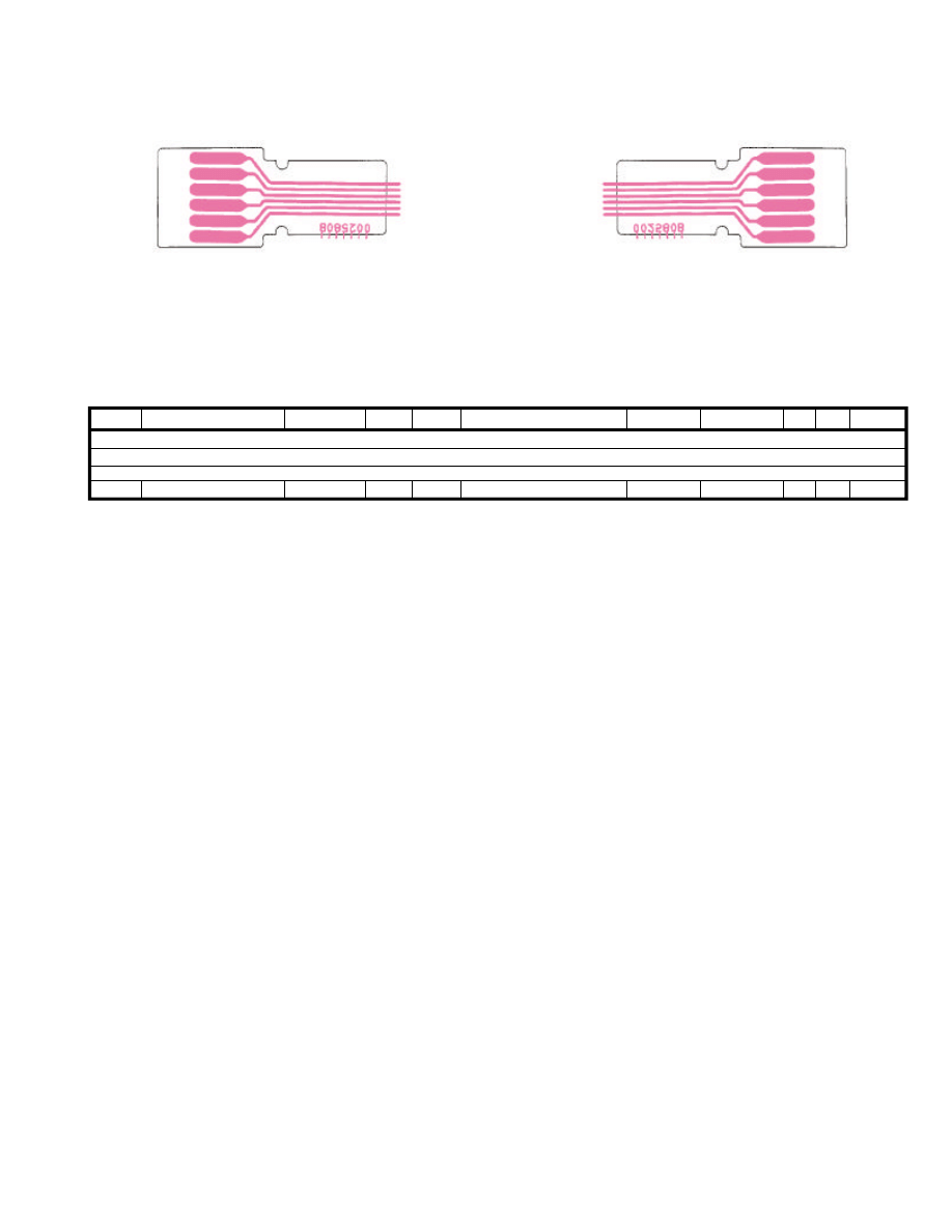
119
Parts List
Parts Layout
Side A
Side B
PCB with Components
1-
Printed Circuit Board
FR002580B
JP8201 WIRE ASSY
T9206739
1-
DESCRIPTION
VALUE
V/W
VERS.
REF.
LOT. SIDE LAY ADR
Connect-2 Unit
Document Outline
- Introduction
- Contents
- Specifications
- Exploded View & Miscellaneous Parts
- Alignment
- Introduction and Precautions
- Required Test Equipment
- Alignment Preparation & Precautions
- Local Oscillator Adjustments
- PLL Adjustments
- PA Unit Adjustments
- HF/50MHz Driver Section Idling Current
- HF/50 MHz Final Idling Current Adjustment
- VHF/UHF Driver Section Idling Current
- VHF/UHF Final Idling Current Adjustment
- TX and RX IF Adjustments
- HF Band RX IF Sensitivity (Coarse Adjust)
- 1st Mixer Balance
- HF/50 MHz Band RX IF Sensitivity
- 144/430 MHz Band RX IF Sensitivity
- 144 MHz Band Front End Gain (Preset)
- 430 MHz Band Front End Gain (Preset)
- HF Band RX IF Gain Adjustment
- 50 MHz Band RX Gain Adjustment
- 144 MHz Band RX Gain Adjustment
- 430 MHz Band RX Gain Adjustment
- S-meter Full Scale Alignment
- Squelch Threshold Level Adjustment
- Noise Blanker Alignment
- TX Adjustments
- HF/50 MHz band TX IF Transformers
- 144/430 MHz band TX IF Transformers
- Trap Adjustment
- CM Coupler Balance
- HF/ 50 MHz Band Over-Current ALC Adjustment
- VHF/UHF Band Over-Current ALC Adjustment
- HF band Output Power Adjustment
- 50 MHz band Output Power Adjustment
- 144 MHz band Output Power Adjustment
- 430 MHz band Output Power Adjustment
- TX Gain Adjustment
- ALC Meter Sensitivity
- PO Meter Sensitivity
- REV ALC Adjustment
- SWR Meter Adjustment
- CW Carrier Level Adjustment
- AM Carrier Level Adjustment
- FM Maximum Deviation
- FM TX LO Offset Adjustment
- TX and RX Carrier Point Adjustment
- BEEP Level
- MAIN-Unit Alignment Points
- Local-Unit Alignment Points
- PA-Unit Alignment Points
- LPF-Unit Alignment Points
- Block Diagram
- Interconnection Diagram
- MAIN Unit
- Circuit Diagram (Lot. 1~4)
- Parts Layout (Lot. 1~4)
- Side A
- Side B
- Circuit Diagram (Lot. 5~)
- Parts Layout (Lot. 5~)
- Side A
- Side B
- Parts List
- C 1xxx
- CD1xxx
- CF1xxx
- CO1xxx
- CV1xxx
- D 1xxx
- J 1xxx
- JP1xxx
- L 1xxx
- Q 1xxx
- R 1xxx
- RL1xxx
- T 1xxx
- TC1xxx
- TH1xxx
- TP1xxx
- VR1xxx
- X 1xxx
- XF1xxx
- 6m-Filter Unit
- Circuit Diagram
- Parts Layout
- Side A
- Side B
- Parts List
- C 17xx
- D 17xx
- J 17xx
- L 17xx
- Q 17xx
- R 17xx
- T 17xx
- BPF Unit
- Circuit Diagram (Lot. 1~)
- Parts Layout (Lot. 1~)
- Side A
- Side B
- Circuit Diagram (Lot. 9~)
- Parts Layout (Lot. 9~)
- Side A
- Side B
- Parts List
- C 18xx
- D 18xx
- J 18xx
- R 18xx
- HPF Unit
- Circuit Diagram (Lot. 1~)
- Parts Layout (Lot. 1~)
- Side A
- Side B
- Circuit Diagram (Lot. 6~)
- Parts Layout (Lot. 6~)
- Side A
- Side B
- Parts List
- C 19xx
- D 19xx
- J 19xx
- JP19xx
- L 19xx
- Q 19xx
- R 19xx
- Audio-Filter Unit
- Circuit Diagram (Lot. 1~)
- Parts Layout (Lot. 1~)
- Side A
- Side B
- Circuit Diagram (Lot. 6~)
- Parts Layout (Lot. 6~)
- Side A
- Side B
- Parts List
- C 19xx
- Q 19xx
- R 19xx
- TP19xx
- Local Unit
- Circuit Diagram
- Parts Layout
- Side A
- Side B
- Parts List
- C 2xxx
- D 2xxx
- J 2xxx
- JP2xxx
- L 2xxx
- Q 2xxx
- R 2xxx
- T 2xxx
- TC2xxx
- TP2xxx
- REF Unit
- Circuit Diagram
- Parts Layout
- Side A
- Side B
- Parts List
- C 28xx
- J 28xx
- Q 28xx
- R 28xx
- TC28xx
- X 28xx
- PA Unit
- Circuit Diagram
- Parts Layout
- Side A
- Side B
- Parts List
- C 3xxx
- D 3xxx
- FB3xxx
- J 3xxx
- JP3xxx
- L 3xxx
- P 3xxx
- Q 3xxx
- R 3xxx
- RL3xxx
- T 3xxx
- TH3xxx
- TP3xxx
- VR3xxx
- LPF Unit
- Circuit Diagram (Lot. 1~)
- Parts Layout (Lot. 1~)
- Side A
- Side B
- Circuit Diagram (Lot. 9~)
- Parts Layout (Lot. 9~)
- Side A
- Side B
- Parts List
- C 5xxx
- D 5xxx
- J 5xxx
- JP5xxx
- L 5xxx
- Q 5xxx
- R 5xxx
- RL5xxx
- TC5xxx
- Display Unit
- Circuit Diagram (Lot. 1~)
- Parts Layout (Lot. 1~)
- Side A
- Side B
- Circuit Diagram (Lot. 34~)
- Parts Layout (Lot. 34~)
- Side A
- Side B
- Parts List
- C 6xxx
- CO6xxx
- D 6xxx
- DS6xxx
- J 6xxx
- L 6xxx
- Q 6xxx
- R 6xxx
- S 6xxx
- TH6xxx
- CNTL Unit
- Circuit Diagram (Lot. 1~)
- Parts Layout (Lot. 1~)
- Side A
- Side B
- Circuit Diagram (Lot. 4~)
- Parts Layout (Lot. 4~)
- Side A
- Side B
- Parts List
- BT7xxx
- C 7xxx
- CO7xxx
- D 7xxx
- J 7xxx
- L 7xxx
- Q 7xxx
- R 7xxx
- S 7xxx
- X 7xxx
- Connect-1 Unit
- Parts Layout
- Side A
- Side B
- Parts List
- J 8xxx
- JP8xxx
- Parts Layout
- VR Unit
- Circuit Diagram
- Parts Layout
- Side A
- Side B
- Parts List
- JP81xx
- VR81xx
- Connect-2 Unit
- TCXO-8 High-Stability Reference Oscillator
- Circuit Diagram
- Parts Layout
- Side A
- Side B
- Parts List
- C 29xx
- J 29xx
- X 29xx
- FTS-27 CTCSS Tone Squelch Unit
- Circuit Diagram
- Parts Layout
- Side A
- Side B
- Parts List
- C 0xxx
- D 0xxx
- P 0xxx
- Q 0xxx
- R 0xxx
- VR0xxx
Wyszukiwarka
Podobne podstrony:
YAESU FT 411mkII User manual
Ft 221 225 Service Manual Mutek
hplj 5p 6p service manual vhnlwmi5rxab6ao6bivsrdhllvztpnnomgxi2ma vhnlwmi5rxab6ao6bivsrdhllvztpnnomg
Oberheim Prommer Service Manual
Korg SQ 10 Service Manual
MAC1500 service manual
Kyocera Universal Feeder UF 1 Service Ma
Proview PZ456 LCD Service Manual
Glow Worm installation and service manual Ultimate 50CF UIS
ewm2000 service manual
Glow Worm installation and service manual Ultimate 60CF UIS
Konica Minolta QMS 7115, 7118 Service Manual
więcej podobnych podstron