1999 Microchip Technology Inc.
DS00718A-page 1
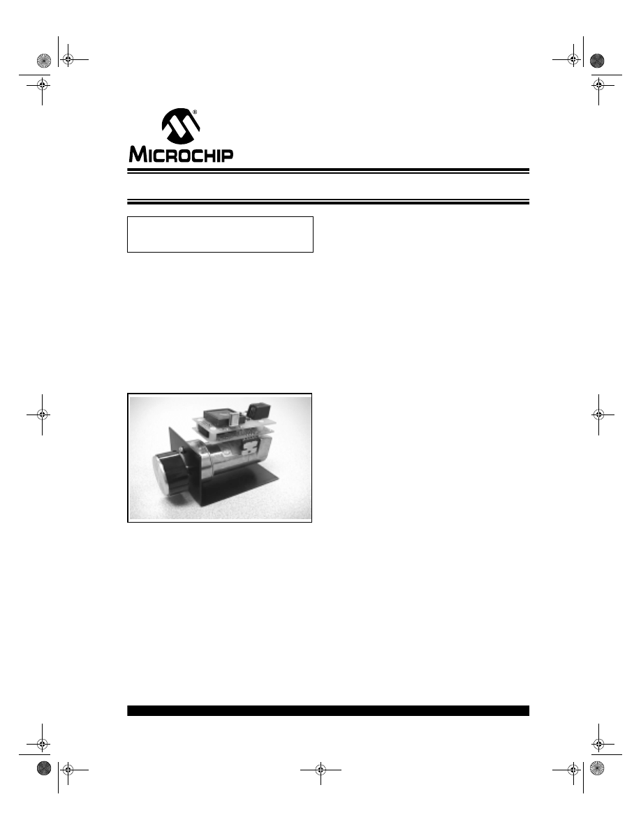
Brush-DC Servomotor Implementation using PIC17C756A
INTRODUCTION
This application note demonstrates the use of a
PIC17C756A microcontroller (MCU) in a brush-DC ser-
vomotor application. The PIC17CXXX family of micro-
controllers makes an excellent choice for cost-effective
embedded servomotor control applications. Some of
the benefits of the PIC17CXXX MCU family include fast
instruction cycle execution (up to 120 ns), an 8 x 8
hardware multiplier, and many useful hardware periph-
erals. The application hardware is shown in Figure 1.
FIGURE 1:
DC SERVOMOTOR
APPLICATION HARDWARE
SYSTEM OVERVIEW
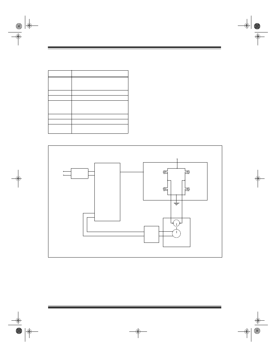
A block diagram of the servomotor system is provided
in Figure 2. The system is comprised of the following
elements:
• PIC17C756A MCU
• RS-232 Interface
• Power Amplifier
• Brush-DC Motor & Rotary Encoder
The MCU is responsible for communications with the
host system, measuring the motor position, calculating
the compensation algorithm and motion profile, and
producing the drive signal sent to the power amplifier.
An RS-232 interface is the primary means of communi-
cation with the MCU. One of the two available USARTs
on the MCU is used for this purpose. The operation of
the motor is controlled and monitored from a host sys-
tem using ASCII commands.
One of the three available pulse-width modulation
(PWM) modules on the MCU is used to generate the
motor drive signal. The PWM frequency is 32.2 kHz at
a device operating frequency of 33 MHz and the mod-
ule provides 10 bits of resolution. The torque applied to
the motor is determined by the PWM duty cycle. The
PWM signal is connected to a ‘H’-bridge power ampli-
fier capable of delivering up to 3A to the DC motor.
A Pittman Inc. 9234 series motor is used in this design.
The motor has a no-load speed of 6151 RPM at 24
volts input and a torque constant of 5.17 oz-in/A (with-
out gearbox). The peak stall current is 8.11A. A 5.9:1
ratio gearbox is installed on the output shaft.
A Hewlett Packard HEDS-9140 rotary optical encoder
is mounted on the rear of the motor with a 500 count-
per-revolution (CPR) encoder wheel mounted on the
shaft. The encoder provides two pulse outputs that are
in phase quadrature and a third index output that can
be used to align the motor shaft to a reference position.
To save space, a stackable printed circuit board (PCB)
system was designed that allows two PCBs to be
mounted on top of the motor (see Figure 1). The bot-
tom PCB contains a 5V regulator, motor driver, encoder
interface, and limit switch buffer circuitry. The upper
PCB contains the PIC17C756A MCU, crystal, RS-232
interface, and reset button.
HARDWARE DESCRIPTION
The design makes extensive use of the hardware
peripherals available on the PIC17C756A. The periph-
erals used in this application are summarized in
Table 1.
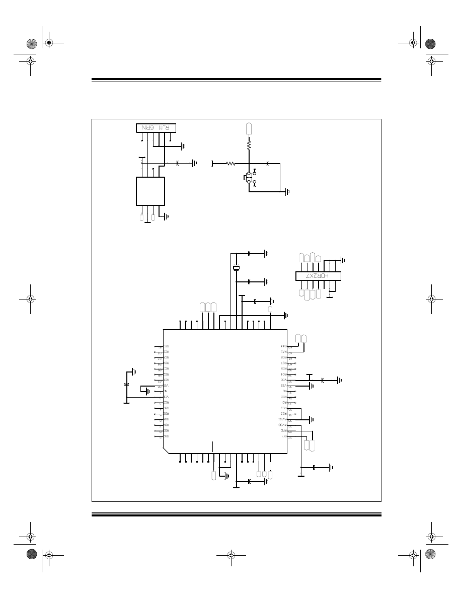
A complete schematic diagram for the application is
given in Appendix A.
Author:
Stephen Bowling
Microchip Technology Inc.
AN718
00718a.book Page 1 Wednesday, October 6, 1999 3:49 PM
AN718
DS00718A-page 2
1999 Microchip Technology Inc.
TABLE 1:
PIC17C756A PERIPHERAL
USAGE FOR DC SERVOMOTOR
APPLICATION
FIGURE 2:
DC SERVOMOTOR BLOCK DIAGRAM
Peripheral
Function
TMR0
Used as a counter to maintain the
incremental up-count from the motor
position encoder
TMR1
PWM1 time-base
TMR2
Servo update time-base
TMR3
Used as a counter to maintain the
incremental down-count from the
motor position encoder
PWM1
Generates drive signal for DC motor
USART1
Terminal communications
I/O
Encoder index signal, PWM ampli-
fier enable, limit switch inputs
RS-232
Transceiver
RX
TX
T0CKI
TCLK3
PIC 17C756A MCU
PWM1
Interface
DC Motor/Encoder
V+
Power Amplifier
Position Feedback
Encoder
00718a.book Page 2 Wednesday, October 6, 1999 3:49 PM
1999 Microchip Technology Inc.
DS00718A-page 3
AN718
Motor Position Feedback
Referring to the schematic diagrams (Figure A-1 to
Figure A-3), the outputs of the rotary encoder are con-
nected to 2.7k pull-up resistors, filtered using RC net-
works, and buffered by Schmidt trigger inverters
U5A - U5C. The outputs of the rotary encoder include
two quadrature outputs and a third index output that is
used to align the shaft of the motor to a known refer-
ence position. The conditioned index signal is con-
nected to I/O pin RF0 of the MCU.
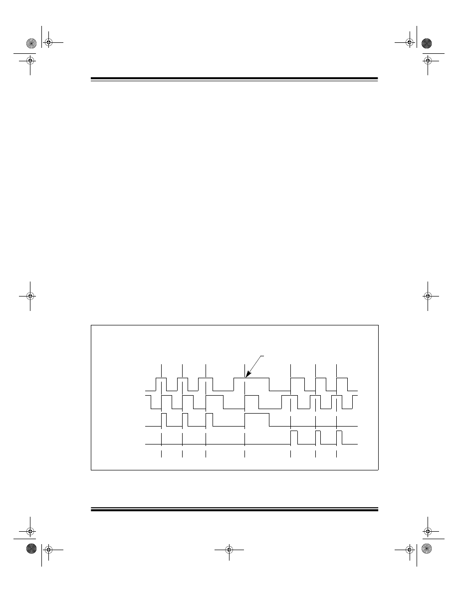
The conditioned quadrature outputs from the rotary
encoder are connected to D flip-flops U6A and U6B.
These D flip-flops decode the quadrature pulse train
into up and down pulse outputs. A timing diagram indi-
cating the operation of the decoder circuit is shown in
Figure 3.
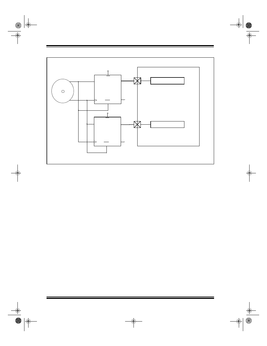
A simplified schematic diagram of the encoder inter-
face is shown in Figure 4. The MCU accumulates the
total distance traveled between servo updates based
on the up and down pulse outputs from U6A and U6B.
To accomplish this, Timer0 and Timer3 are configured
as counters with external clock inputs. The output of D
flip-flop U6A (up pulses) is connected to the Timer0
external clock input and the output of D flip-flop U6B
(down pulses) is connected to the Timer3 external
clock input. Each of these timer registers is 16 bits
wide.
Three external logic inputs are provided at connector
J4 on the motor driver PCB and are intended for
mechanical limit switch sensing. These inputs could
also be used to activate certain motor functions. The
inputs are filtered and buffered by U5D – U5F similar to
the encoder interface circuitry. The conditioned limit
switch signals are connected to I/O pins RF1, RF2, and
RF3 of the MCU.
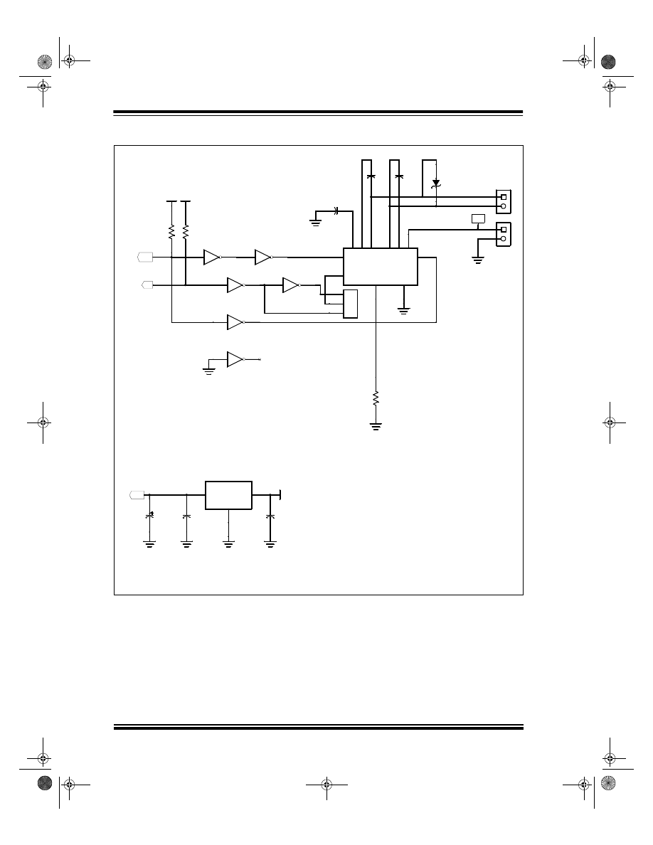
PWM Amplifier
Integrated circuit U1 is an H-bridge driver that uses
DMOS output devices and can deliver up to 3A output
current at supply voltages up to 52V. The device has an
internal charge pump for driving the high-side transis-
tors and dead-time circuitry to prevent cross-conduc-
tion of the output devices. Each side of the bridge may
be driven independently and the inputs are TTL com-
patible. An enable input and automatic thermal shut-
down are also provided. A transient voltage suppressor
is connected across the motor terminals to prevent volt-
age spikes generated by the motor inductance from
damaging the bridge.
The PWM1 output from the MCU is buffered through
inverters U3A, U3B, and U3D and connected to both
sides of the H-bridge driver IC. One side of the bridge
is driven with a inverted PWM signal. By driving the
bridge in this manner, the motor may be turned in either
direction depending on the PWM duty cycle. A 50%
PWM duty cycle will produce zero motor torque. A
100% duty cycle will produce maximum motor torque in
the forward direction, while a 0% duty cycle will pro-
duce maximum motor torque in the opposite direction.
An enable signal from I/O pin RF4 of the MCU is con-
nected to the bridge driver through inverter U3C. This
signal turns the output of the PWM amplifier on or off.
FIGURE 3:
ENCODER TIMING
Motor Reverses Direction Here
ENC. CH. A
ENC. CH. B
Up Count
Down Count
00718a.book Page 3 Wednesday, October 6, 1999 3:49 PM
AN718
DS00718A-page 4
1999 Microchip Technology Inc.
FIGURE 4:
SIMPLIFIED ENCODER INTERFACE SCHEMATIC
Servo Update Timing
The servo update calculations are performed in an
interrupt service routine and are synchronized with the
output of PWM1. This is desirable because the duty
cycle is updated at multiples of the PWM period. The
PWM1 output is connected to the TCLK12/RB4 pin and
is used as a clock source for Timer2. Timer2 has an
associated period register, PR2. When the value of
Timer2 is equal to the value loaded in PR2, Timer2 is
reset to 0 and an interrupt is generated. By adjusting
the value in PR2, the servo update frequency may be
adjusted to any ratio of the PWM1 output. At a device
operating frequency of 33 MHz, the frequency of
PWM1 is 32.2 kHz. A 3.9 kHz servo update frequency
will be achieved with the value in PR2 set to 8.
RS-232 Transceiver
The TX and RX pins of USART1 are connected to a
Dallas Semiconductor DS275 RS-232 transceiver. The
chip was selected for its small size and because it is
line-powered. The chip uses power from the receive
input to generate the correct RS-232 voltage levels
while transmitting. To save space, RS-232 connections
are made through a RJ-11 connector on the MCU PCB.
Power Supply
Voltage regulator VR1 provides 5 volts to the MCU, RS-
232 driver, interface logic, and the rotary encoder. The
system is designed to operate at any supply voltage
between 10 volts and 24 volts. The supply voltage is
connected directly to the PWM amplifier.
Up
Down
PIC17C756A
ENCODER
A
B
D
C
Q
Q
CLR
PR
D
C
Q
Q
PR
CLR
RA1/T0CKI
RB5/TCLK3
Timer0
Timer3
+5
+5
74HC74
74HC74
U6A
U6B
00718a.book Page 4 Wednesday, October 6, 1999 3:49 PM

1999 Microchip Technology Inc.
DS00718A-page 5
AN718
SOURCE CODE
The source code is written in the C programming lan-
guage for ease of implementation and was compiled
using the MPLAB-C17™ compiler. A complete source
code listing for the application has been provided in
Appendix B.
The source code performs four basic functions:
• RS-232 communication
• Motor position measurement
• Compensator algorithm calculation
• Motion profile calculation
All functions, except the RS-232 communications are
performed in an interrupt service routine.
RS-232 Communications
The DC motor software allows control of the motor
operating mode and parameter changes via a remote
terminal with a RS-232 link operating at 19.2 kbaud. All
RS-232 communication takes place in the main pro-
gram loop. The USART1 reception interrupt flag
(RC1IF) is polled to detect when a character has been
received. Each received character is stored in a buffer,
echoed to the USART, and the buffer index is incre-
mented. This continues until the buffer is full or a
<CR> is received. After a <CR> is received, the buffer
contents are checked for numerical or command data
and a ‘READY>’ prompt is sent to the terminal. If the
command is not recognized, an error message is sent
out.
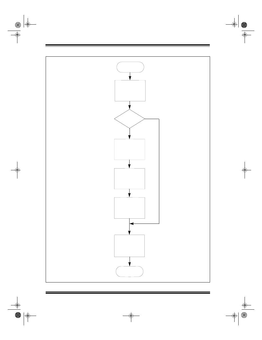
Servo Updates
The servo calculations are performed each time a
Timer2 interrupt occurs. A flowchart of the servo inter-
rupt service routine (ISR) is shown in Figure 5.
32-bit Operations
This application makes extensive use of 32-bit values.
Since MPLAB-C17 does not provide direct support for
32-bit variable types, the 32-bit variables used in the
program are declared as unions. The use of a union in
the C programming language allows multiple variable
types to share the same data space. A union with the
name of ‘LONG’ has been declared in the source code.
The union LONG consists of an array of four characters
and an array of two integers. Therefore, any variables
that are declared with this data type may be manipu-
lated as four bytes or two integers. Additionally, the
contents of the entire union may be copied to another
location by simply assigning it to another union of the
same type.
Position Updates
During each servo update period, the function
UpdatePosition()
is called. The count values in
Timer0 and Timer3 are used to find the total motor dis-
tance traveled during the previous servo update period.
The counters are never cleared to avoid the possibility
of losing count information. Instead, the values of the
Timer0 and Timer3 registers saved during the previous
sample period are subtracted from the present values
using two’s-complement signed arithmetic. This calcu-
lation provides the total number of up and down pulses
accumulated during the servo update period. The use
of two’s complement arithmetic accounts for a timer
overflow that may have occurred since the last read.
The down pulse count is then subtracted from the up
pulse count, which provides a signed result indicating
the total distance (and direction) traveled during the
sample period. This value also represents the mea-
sured velocity of the motor in encoder counts per servo
update period and is stored in the variable
mvelocity
.
The measured position of the motor is stored in the
union
mposition
. The upper 24 bits of
mposition
holds the position of the motor in encoder counts. The
lower eight bits of
mposition
represent fractional
encoder counts. The value of
mvelocity
is added to
mposition
at each servo update period to find the
new position of the motor. With 24 bits, the absolute
position of the motor may be tracked through 33,554
shaft revolutions using a 500 CPR encoder. The size of
mposition
can be increased as necessary to track
greater distances.
00718a.book Page 5 Wednesday, October 6, 1999 3:49 PM
AN718
DS00718A-page 6
1999 Microchip Technology Inc.
FIGURE 5:
SERVO ISR FLOWCHART
END
START
UPDATE MOTOR
POSITION
VELOCITY
OR POSITION
MODE?
UPDATE
PROFILE
MOTION
CALCULATE
POSITION
ERROR
CALCULATE
PID ALGORITHM
UPDATE PWM
DUTY CYCLE
NO
YES
00718a.book Page 6 Wednesday, October 6, 1999 3:49 PM

1999 Microchip Technology Inc.
DS00718A-page 7
AN718
The theoretical maximum encoder bit rate is deter-
mined by the number of bits in the counter registers and
the servo update rate. If the counter should overflow
between servo update periods, motor position informa-
tion will be lost. A 16-bit counter register, for example,
would provide 2
16
– 1 counts before an overflow
occurred. Since two’s complement arithmetic is used,
the number of encoder counts during a given sample
period must be limited to 2
15
– 1, or 32767. The max-
imum encoder rate is determined by multiplying the
servo sampling frequency by the maximum encoder
counts per sample. For this design, the servo update
frequency is 3.9 kHz, which gives a theoretical maxi-
mum encoder rate of 128 MHz. In practice, the encoder
rate is limited by the external clock timing specifications
for Timer0 and Timer3. The minimum external clock
period for Timer0 and Timer3 is T
CY
+ 40ns. There-
fore, the maximum encoder rate is 6.2 MHz for a device
operating frequency of 33 MHz.
PID Algorithm
The MCU must calculate and provide the correct motor
drive signal based on the received motion commands
and position/velocity feedback data. A compensation
algorithm is used to ensure that the feedback loop is
stabilized. Many types of algorithms may be used
including various implementations of digital filters,
fuzzy-logic, and the PID (proportional, integral, deriva-
tive) algorithm. A PID algorithm is used in this applica-
tion since it is widely used in industrial applications and
is easy to implement.
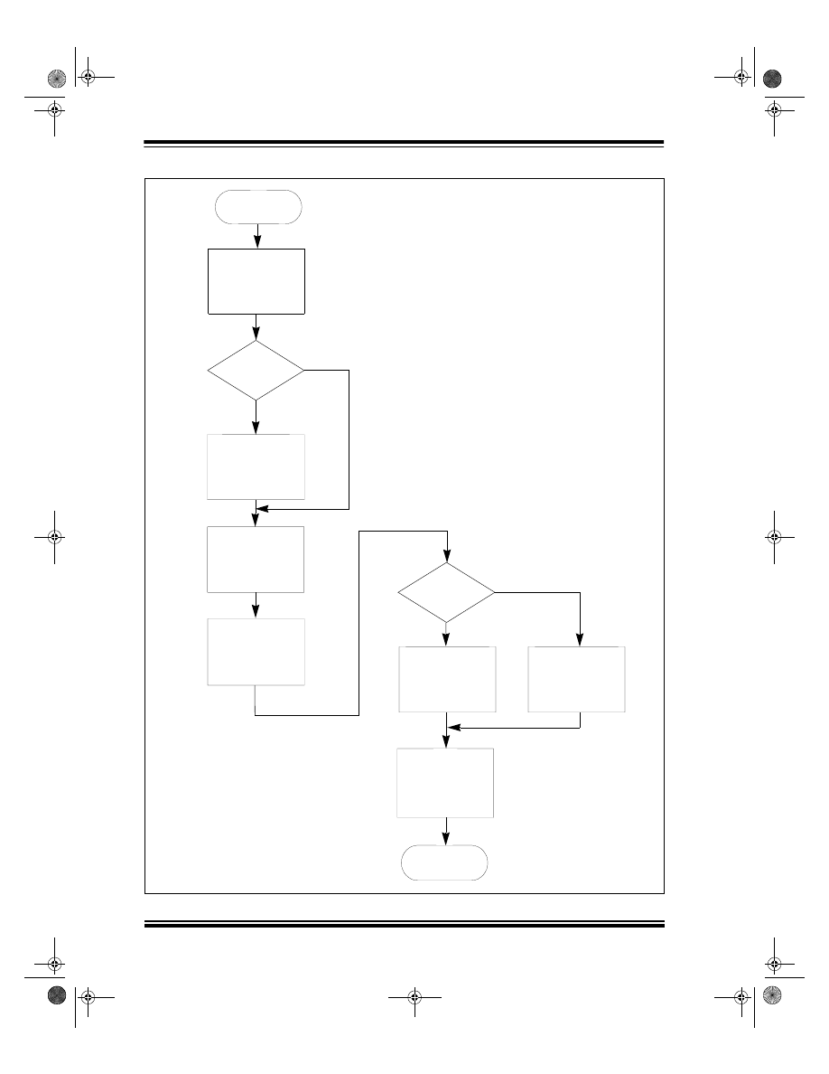
Figure 6 shows a flowchart indicating the function of
the PID algorithm as it is implemented here. During
each iteration of the servo loop, a position error is cal-
culated and is used as the input to the algorithm. To
control the operation of the PID algorithm, each of the
three terms has a gain constant that can be adjusted in
real-time by the user. Each term of the PID algorithm is
calculated using a 16 bit x 16 bit signed multiplication
algorithm with the PID gain constants
kp
,
ki
, and
kd
defined as 16-bit signed integers.
The union
position
holds the commanded motor
position. The value of
mposition
, the measured
motor position, is subtracted from
position
to find the
present error in encoder counts. The least significant
eight bits of these variables represent fractional
encoder counts and are not used in the PID algorithm
calculations. The
sub32()
function is used to subtract
the values. The values to be subtracted are placed in
aarg
and
barg
. The result of the subtraction is avail-
able in
aarg
after the function has been called. The
error calculation result in
aarg
is truncated to a signed
16-bit integer and stored in
u0
.
The multiplication routine is implemented as inline
assembly instructions in the C source code. The algo-
rithm executes in 36 cycles and takes advantage of the
8 x 8 hardware multiplier on the MCU. To perform the
multiplication, the signed 16-bit integers to be multi-
plied are loaded into the
multplr
and
multcnd
vari-
ables and the function
mult()
is called. The 32-bit
multiplication result is available in the union
aarg
. The
add32()
function is used to add the 32-bit terms of the
PID algorithm.
The proportional term of the PID algorithm provides an
output that is a function of the immediate position error,
u0
.
The integral term of the PID algorithm accumulates
successive position errors calculated during each
servo loop iteration and improves the low frequency
open-loop gain of the servo system. The effect of the
integral term is to reduce small steady-state position
errors.
If the
stat.saturated
bit is set because the PWM
output during the previous servo update period was
saturated, the current position error is not be added to
the integral value. This prevents a condition known as
‘integrator-windup’ that occurs when the integral term
continues to accumulate error when the output is satu-
rated. When the output is no longer saturated, the inte-
gral term ‘unwinds’ and causes abrupt motion as the
accumulated error is reduced.
The differential term of the PID algorithm is a function
of the difference in error between the current servo
update period and the previous one. The integral term
improves the high frequency open-loop response of the
servo system.
After the three terms of the PID algorithm are summed,
the 32-bit result stored in
ypid
is saturated to 24 bits.
The 16-bit signed integer
ypwm
is used to set the PWM
duty cycle. The upper 16 bits of
ypid
are used to set
the duty cycle, which effectively divides the output of
the PID algorithm by 256. The range of the duty cycle
is restricted so that the PWM duty cycle cannot be less
than 1% or greater than 99%. This ensures that Timer2
will always receive a valid clock input for the servo
update timing interrupt. If beyond the limits,
ypwm
is set
to the maximum allowable positive or negative value
and
stat.saturated
is set to ‘1’. An offset value of
512 must be added to
ypwm
before it is written to the
PWM duty cycle registers. (For 10-bit PWM resolution,
a value of ‘0’ written to the duty cycle registers provides
a 0% duty cycle and a value of 1023 provides a 100%
duty cycle.)
00718a.book Page 7 Wednesday, October 6, 1999 3:49 PM
AN718
DS00718A-page 8
1999 Microchip Technology Inc.
FIGURE 6:
PID ALGORITHM FLOWCHART
END
START
CALCULATE
PROPORTIONAL
SATURATION
FLAG SET?
INTEGRAL (2)
ADD ERROR TO
CALCULATE
INTEGRAL TERM
AND ADD TO YPID
CALCULATE
UPDATE PWM
DUTY CYCLE
NO
YES
YES
NO
TERM (1)
ADD TO YPID (4)
DIFFERENTIAL
TERM AND
IS OUTPUT
SATURATED?
SET
FLAG
CLEAR
SATURATION
FLAG
SATURATION
(1)
ypid = kp
•
u0
(2)
Integral = Integral + u0
(3)
ypid = ypid + Integral
•
ki
(4)
ypid = ypid + kd(u0 - u1)
(3)
00718a.book Page 8 Wednesday, October 6, 1999 3:49 PM

1999 Microchip Technology Inc.
DS00718A-page 9
AN718
Motion Profile
For optimum motion control, a method must be imple-
mented that will control the motor acceleration and
deceleration. Motion will be abrupt without the profile,
causing excessive wear on the mechanical compo-
nents and degrading the performance of the compen-
sation algorithm.
For this application, a simple motion profile that gener-
ates trapezoidal (or triangular) moves has been imple-
mented. The profile characteristics are adjusted by
specifying a 16-bit velocity limit,
vlim
, and a 16-bit
acceleration value,
accel
. The motion profile is used
in Velocity Mode and Position Mode. If the motor is
operating in one of these modes, the function
UpdateTrajectory()
is called each time
ServoISR()
is executed.
A specific motor velocity is established by adding an
offset value to the commanded position at each servo
update period. The 32-bit variable
velact
is used in
the profile to hold the present commanded velocity of
the motor. The lower 24 bits of
velact
and the least
significant 8 bits of
position
, the commanded motor
position, represent fractional encoder counts. The pur-
pose of these additional bits is to increase the range of
velocities that may be achieved. To achieve a particular
motor velocity, the upper 16 bits of
velact
are added
to
position
during each step of the profile. This
allows the commanded motor velocity to vary between
1/256 counts/T
S
and 127 counts/T
S
. The actual velocity
range of the motor is dependent on the servo update
rate and the resolution of the encoder. With a 3.9 kHz
servo update rate and a 500 CPR encoder, the range
of commanded motor velocities is from 1.8 RPM to
59,436 RPM.
Motor acceleration/deceleration is accomplished in a
manner similar to the motor velocity. The value of
accel
is added to or subtracted from
velact
at each
servo update period.
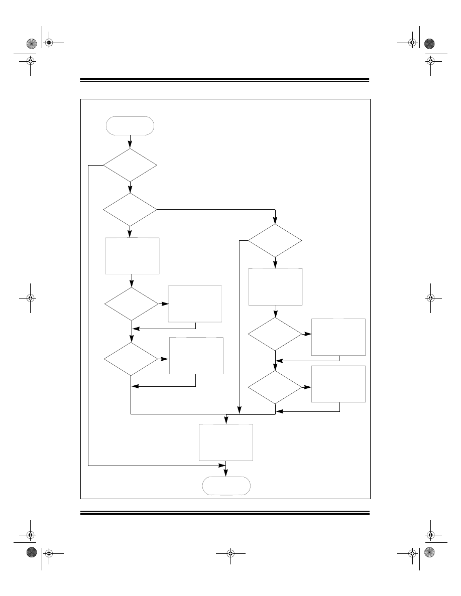
A flowchart for the operation of the motion profile in
Velocity Mode is shown in Figure 7. In Velocity Mode,
data entered at the prompt is stored in the commanded
velocity variable,
velcom
. After
velcom
is updated,
the motor begins to accelerate or decelerate to the new
commanded velocity. Acceleration continues until
velact
is equal to
velcom
or the velocity limit,
vlim
,
has been exceeded. The value of
velact
is added to
the commanded motor position,
position
. The motor
will continue to run at the commanded velocity or the
velocity limit until further velocity data is received. If the
output is saturated (
stat.saturated = ‘1’
) during
a particular servo update period, the commanded posi-
tion is not changed.
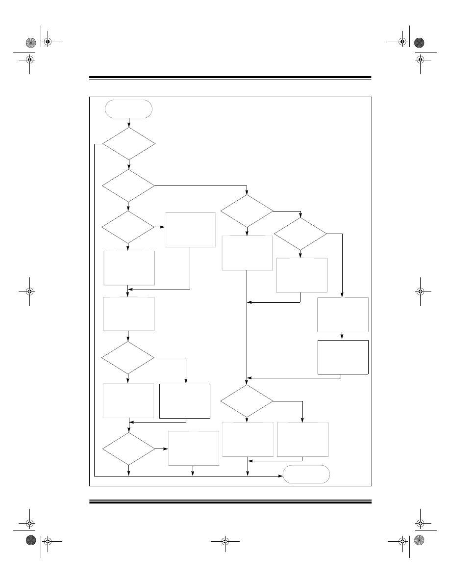
A flowchart for the operation of the motion profile in
Position Mode is shown in Figure 8. In Position Mode,
a 16-bit relative movement distance is entered as
encoder counts divided by 256. The total movement
distance is divided by 2 and placed in
phase1dist
. A
second variable,
flatcount
, is set to zero. The direc-
tion of the move is determined and stored in the
stat.neg_move
flag. The final move destination is
calculated based on the present measured position
and is stored in
fposition
. Finally, the
stat.move_in_progress
flag is set. Further posi-
tion commands are ignored until the move has com-
pleted and this flag is cleared.
The motor begins to accelerate and the value of
velact
is subtracted from
phase1dist
at each servo
update period to keep track of the distance traveled in
the first half of the move. The value of
velact
is added
or subtracted from the commanded motor position,
position
, depending on the state of the
stat.neg_move
flag. The motor stops accelerating
when
velact
is greater than
vlim
. After the velocity
limit has been reached,
flatcount
is incremented at
each servo update period to keep track of the time
spent in the flat portion of the move.
The first half of the move is completed when
phase1dist
becomes negative. At this time, the
stat.phase
flag is set to ‘1’. The variable
flat-
count
is then decremented at each servo period.
When
flatcount = 0
, the motor begins to deceler-
ate. The move is complete when
velact = 0.
The
previously calculated destination in
fposition
is writ-
ten to the commanded motor position and the
stat.move_in_progress
flag is cleared at this
time.
00718a.book Page 9 Wednesday, October 6, 1999 3:49 PM
AN718
DS00718A-page 10
1999 Microchip Technology Inc.
FIGURE 7:
MOTION PROFILE FLOWCHART – VELOCITY MODE
START
IS OUTPUT
SATURATED?
CURRENT
VELOCITY LESS
THAN COMMANDED
VELOCITY?
ACCELERATE
CURRENT
VELOCITY GREATER
THAN COMMANDED
VELOCITY?
VELOCITY
GREATER THAN
VELOCITY
SET CURRENT
EQUAL TO
COMMANDED VELOCITY
SET CURRENT
EQUAL TO
VELOCITY
VELOCITY
VELOCITY LIMIT
IS
CURRENT
IS
LIMIT?
ADD CURRENT
VELOCITY TO
COMMANDED
POSITION
END
CURRENT
VELOCITY GREATER
THAN COMMANDED
VELOCITY?
IS
DECELERATE
EQUAL TO
COMMANDED VELOCITY
VELOCITY
SET CURRENT
SET CURRENT
EQUAL TO
VELOCITY
VELOCITY LIMIT
CURRENT
VELOCITY LESS
THAN COMMANDED
VELOCITY?
IS
IS
CURRENT
VELOCITY
GREATER THAN
VELOCITY
LIMIT?
NO
YES
NO
YES
NO
NO
NO
NO
NO
YES
YES
YES
YES
YES
00718a.book Page 10 Wednesday, October 6, 1999 3:49 PM
1999 Microchip Technology Inc.
DS00718A-page 11
AN718
FIGURE 8:
MOTION PROFILE FLOWCHART – POSITION MODE
START
YES
NO
YES
NO
NO
YES
YES
NO
YES
NO
YES
NO
NO
YES
NO
YES
IS
OUTPUT
SATURATED?
IN
PHASE 1 OF
MOVE?
HAS
VELOCITY
LIMIT BEEN
REACHED?
ACCELERATE
INCREMENT
FLAT COUNT
IS
FLAT COUNT
0?
IS
CURRENT VELOCITY
0?
DECREMENT
FLAT COUNT
DECELERATE
CLEAR
MOVE IN PROGRESS
FLAG
SET COMMANDED
POSITION EQUAL TO
CALCULATED FINAL
POSITION
SUBTRACT CURRENT
VELOCITY FROM
PHASE 1 DISTANCE
IS
MOVE POSITIVE?
IS
MOVE POSITIVE?
ADD CURRENT
COMMANDED POSITION
VELOCITY TO
COMMANDED POSITION
VELOCITY TO
SUBTRACT CURRENT
IS
PHASE 1 DISTANCE
NEGATIVE?
SET FLAG TO
INDICATE PHASE 2
ADD CURRENT
COMMANDED POSITION
VELOCITY TO
COMMANDED POSITION
VELOCITY TO
SUBTRACT CURRENT
END
00718a.book Page 11 Wednesday, October 6, 1999 3:49 PM

AN718
DS00718A-page 12
1999 Microchip Technology Inc.
USER INTERFACE
When power is first applied to the motor, the user will
see a ‘READY>’ prompt appear on the terminal. At this
time, the DC motor is ready to receive commands. A
summary of all the commands is given in Table 2.
The software that controls the DC motor allows three
basic modes of operation that are selectable from the
remote terminal. These modes include Manual Mode,
Velocity Mode, and Position Mode.
The default mode for the motor at power-up is Manual
Mode. No position feedback is used in Manual Mode.
The data entered at the prompt directly controls the
PWM duty cycle delivered to the motor.
In Velocity Mode, the entry data specifies the signed
motor velocity, which is given as encoder counts per
sample period multiplied by 256. When new velocity
data has been entered, the motor will accelerate or
decelerate to the new velocity at a rate specified by the
acceleration value. The motor will not accelerate if the
velocity limit has been reached.
In Position Mode, the entry data specifies a signed
16-bit relative move distance. The movement distance,
entered at the prompt, is given as encoder counts
divided by 256. When a move distance is specified, a
motion status flag is set and any additional move data
are ignored until the current move is complete.
The profile of the move will be trapezoidal or triangular
depending on the total move distance, the velocity limit,
and the acceleration value. For a trapezoidal move, the
motor will accelerate to the velocity limit and remain at
that velocity until it is time for the motor to decelerate.
If half of the move distance has been traveled before
the motor reaches the velocity limit, the motor will begin
to decelerate and the move will be triangular.
The motor operating parameters are displayed using
the ‘R’ command. Any of the parameters may be mod-
ified by first entering the command to change the
parameter, followed by a carriage return (<CR>). The
parameter is then modified by entering the new value
followed by a <CR>. The user can then verify that the
parameter was changed by using the ‘R’ command
again.
SUMMARY
The use of the PIC17C756A MCU in a DC servomotor
application has many features that allow a cost-effec-
tive implementation with few external components.
These include (2) 16-bit counters for position measure-
ment, hardware PWM modules, and a hardware multi-
plier for high computational throughput.
ServoISR()
, as written for this application, executes
in 780 instruction cycles. For a servo update rate of
3.9kHz and a MCU clock frequency of 33 MHz, only
37% of the total MCU processing time is consumed.
This provides additional time for performing unrelated
tasks, computing more complicated compensator algo-
rithms, or increasing the servo update rate.
TABLE 2:
DC SERVO MOTOR COMMAND SUMMARY
Command
Data Range
Description
M <CR>
-500
≤
data
≤
500
Changes to the manual mode of operation. All subsequent data
input is written directly to the PWM output.
V <CR>
-32768
≤
data
≤
32767
Changes to velocity mode. All subsequent data input is velocity in
encoder counts per sample period multiplied by 256.
P <CR>
-32768
≤
data
≤
32767
Changes to position mode. All subsequent data input is a relative
position move in encoder counts multiplied by 256.
W <CR>
Enables/disables PWM drive to the motor; the default is disabled.
R <CR>
Displays current K
P
, K
I
, K
D
, velocity limit, and acceleration limit.
L <CR>
Displays the present motor position in hexadecimal format.
KP <CR> data <CR>
-32768
≤
data
≤
32767
Changes the proportional gain factor of the PID algorithm. The
command is followed by the data value.
KI <CR> data <CR>
-32768
≤
data
≤
32767
Changes the integral gain factor of the PID algorithm. The com-
mand is followed by the data value.
KD <CR> data <CR>
-32768
≤
data
≤
32767
Changes the differential gain factor of the PID algorithm. The com-
mand is followed by the data value.
KV <CR> data <CR>
0
≤
data
≤
65535
Changes the velocity limit of the trajectory profile. The data value is
encoder counts per sample period multiplied by 256. The com-
mand is followed by the data value.
KA <CR> data <CR>
0
≤
data
≤
65535
Changes the acceleration value for the trajectory profile. The com-
mand is followed by the data value.
KS <CR> data <CR>
Changes the servo update rate. The data value is written to the
period register for Timer2. The servo update rate will be the PWM
frequency divided by the value entered here.
00718a.book Page 12 Wednesday, October 6, 1999 3:49 PM
1999 Microchip Technology Inc.
DS00718A-page 13
AN718
APPENDIX A:
SCHEMATICS
FIGURE A-1:
SCHEMATIC 1
+5
V
INDE
X
LI
M
+
LI
M
-
GP
I
EN
MC
L
R
TX
1
RX
1
+5V
+5V
C8
.1uF
C10
.1uF
.1uF
C11
+5V
.1uF
C1
DWN
+5
V
C12
22
pF
33.
0M
Y1
C13
22pF
PW
M
C9
.1uF
UP
4
GN
D
1
RX
o
u
t
2
Vd
r
v
3
TX
in
5
TX
o
u
t
6
NC
7
RX
in
8
VC
C
U1
DS
2
7
5
PW
M
LI
M
+
INDE
X
+5V
4
3
2
1
S1
C5
.1
uF
4.7
k
R1
47
0
R2
MC
L
R
+5V
RX
1
+5V
C14
.1uF
1
2
3
5
7
4
6
8
11
13
12
14
9
10
J5
DW
N
EN
LI
M
-
GP
I
UP
1
2
3
4
6
5
J1
+5V
26
RF2
25
RF3
10
RD1
24
RF4
23
RF5
22
RF6
21
RF7
20
VD
D
19
VS
S
18
NC
17
TE
S
T
16
MCLR
15
RE
3
14
RE
2
13
RE
1
12
RE
0
11
RD0
44
RA
1
60
RA
0
45
RA
2
46
RA
3
47
RB
6
48
RB
7
49
VD
D
50
OS
C
1
51
OS
C
2
52
NC
53
VS
S
54
RB
2
55
RB
5
56
RB
4
57
RB
3
58
RB
1
59
RB
0
U2
PIC
17C756A
PW
M
TX
1
00718a.book Page 13 Wednesday, October 6, 1999 3:49 PM
AN718
DS00718A-page 14
1999 Microchip Technology Inc.
FIGURE A-2:
SCHEMATIC 2
9
8
74HC04
U3:D
R1
.2, 5W
3
OUT
1
IN
U4
LM2940T
+5V
C6
.1
uF
C5
100uF, 22V
C4
.1
uF
+VS
13
12
74HC04
U3:F
1
2
3
J6
C2
.01
uF
4.7k
R6
R7
4.7k
1
2
74HC04
U3:A
3
4
74HC04
U3:B
5
6
74HC04
U3:C
C1
.1
uF
+5V
5
IN_1
11
4
9
7
IN_2
3
1
8
2
10
6
SUB
L6203
U1
+5V
PWM
EN
11
10
74HC04
U3:E
+VS
2
1
J2
2
1
J1
POWER
C3
.01
uF
Z1
2
COM
EN
MOTOR
CONNECTIONS
INPUT
00718a.book Page 14 Wednesday, October 6, 1999 3:49 PM
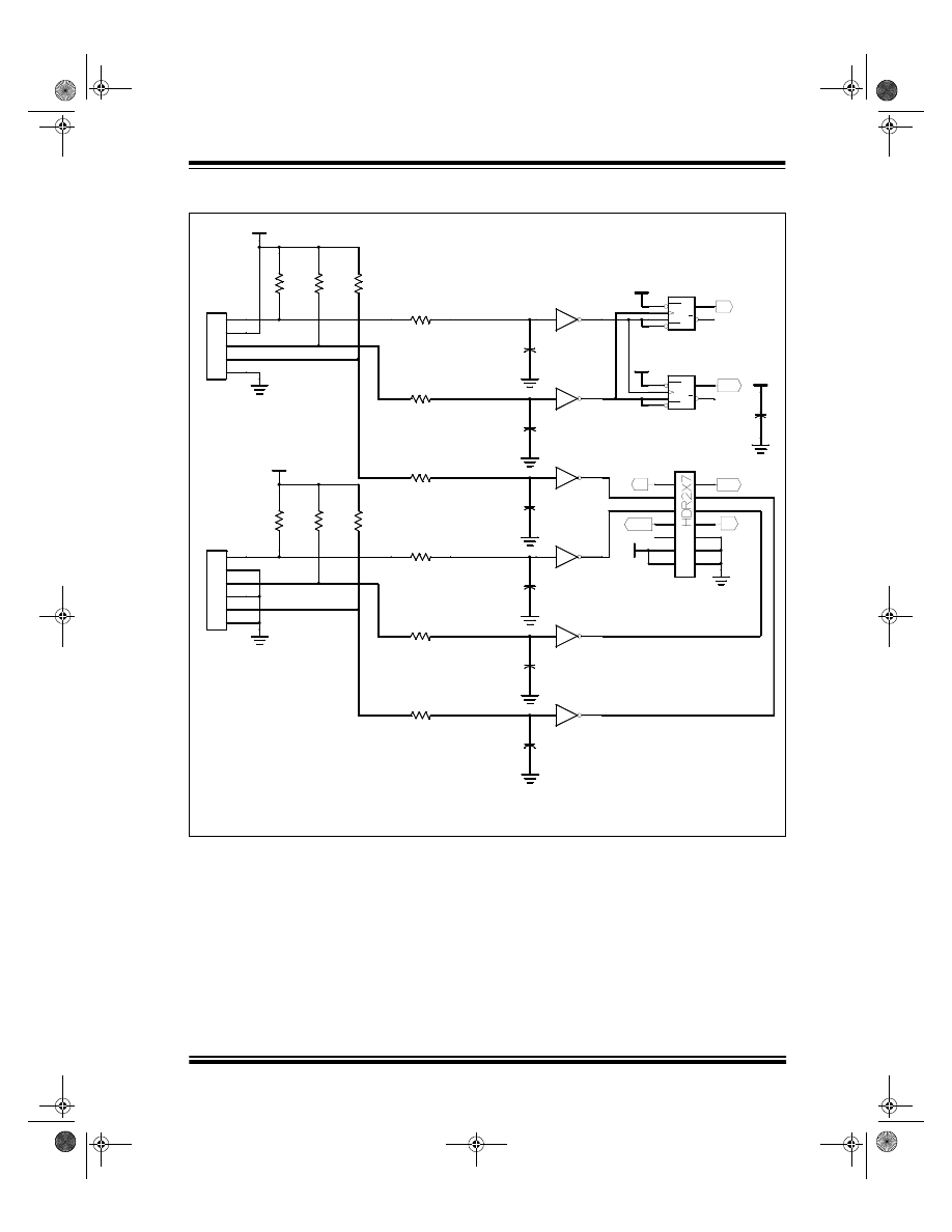
1999 Microchip Technology Inc.
DS00718A-page 15
AN718
FIGURE A-3:
SCHEMATIC 3
PWM
6
5
U5:C
74HC14
2.7k
R19
2.7k
R18
2.7k
R17
2.7k
R13
2.7k
R14
2.7k
R15
2.7k
R16
C12
56pF
C11
56pF
C10
56pF
C9
56pf
12
13
U5:F
74HC14
8
9
U5:D
74HC14
10
11
U5:E
74HC14
+5V
LIMIT
SWITCH
INPUTS
1
2
3
4
5
6
J4
1
2
3
5
7
4
6
8
11
13
12
14
9
10
J5
+5V
1
2
3
4
5
J3
+5V
ROTARY
ENCODER
CONNECTIONS
2
1
U5:A
74HC14
4
3
U5:B
74HC14
C7
56pF
C8
56pF
2.7k
R12
2.7k
R11
R8
2.7k
R9
2.7k
R10
2.7k
6
Q
5
Q
1 CLR
2 D
3
C
4 PRE
U6:A
74HC74
+5V
+5V
8
9
Q
13 CLR
12 D
11
C
10 PRE
U6:B
74HC74
+5V
.1uF
C13
EN
DWN
UP
DWN
UP
Q
00718a.book Page 15 Wednesday, October 6, 1999 3:49 PM

AN718
DS00718A-page 16
1999 Microchip Technology Inc.
APPENDIX B:
SOURCE CODE
//---------------------------------------------------------------------
//
17motor.c
//
Written By:
Steve Bowling, Microchip Technology
//
//
This source code demonstrates the use of the PIC17C756A in a
//
brush-DC servomotor application and is written for the MPLAB-C17
//
compiler. The following files should be included in the C17
//
project, which is compiled for the large memory model:
//
//
17motor.c
--
//
c0l17.o
--
startup code
//
idata17.o
--
initialized data support
//
p17c756.o
--
processor definition module
//
int756l.o
--
interrupt handler routines
//
pmc756l.lib
--
library functions
//
p17c756l.lkr
--
linker script
//
//---------------------------------------------------------------------
#include <p17c756.h>
#include <stdlib.h>
#include <usart16.h>
#include <string.h>
#include <timers16.h>
#include <captur16.h>
#include <pwm16.h>
#include <ctype.h>
#include <delays.h>
#include <mem.h>
#define F 1
#define W 0
const rom char start[] = “\r\n\r\n17C756A DC Servomotor”;
const rom char ready[] = “\n\rREADY>”;
const rom char error[] = “\n\rERROR!”;
char inpbuf[8];
// input buffer for ASCII commands
char data[9];
// buffer for ASCII conversions
char command;
// holds the last parameter change
// command that was received
unsigned char
i,
// index to ASCII buffer
udata,
// received character from USART
mode,
// determines servo mode
tempchar,
PRODHtemp,
// temp context saving for ISR
PRODLtemp,
// “
FSR0temp,
// “
FSR1temp;
// “
struct {
// holds status bits for servo
unsigned phase:1;
// first half/ second half of profile
unsigned neg_move:1;
// backwards relative move
unsigned move_in_progress:1;
//
unsigned saturated:1;
// servo output is saturated
unsigned bit4:1;
unsigned bit5:1;
unsigned bit6:1;
unsigned bit7:1;
} stat ;
int
00718a.book Page 16 Wednesday, October 6, 1999 3:49 PM

1999 Microchip Technology Inc.
DS00718A-page 17
AN718
tempint3,
//
tempint2,
//
tempint1,
//
tempint0,
//
UpCount,
// encoder up counts during sample period
DnCount,
// encoder down counts “ “ “
u0,u1,
// current and previous position error
kp,ki,kd,
// PID gain constants
integral,
// PID error accumulation
ypwm,
// duty cycle derived from PID calculation
multcnd,multplr,
// holds values to be multiplied in mult()
velcom,vlim;
// commanded velocity, velocity limit
unsigned int accel;
// acceleration parameter for motion profile
union LONG
{
unsigned int ui[2];
int i[2];
char b[4];
};
union LONG
aarg,
// Used for math calculations.
barg,
// “
ypid,
// Used to hold result of the PID
// calculations.
position,
// Commanded position.
mposition,
// Actual measured position.
fposition,
// Final commanded position of motion
// profile.
poserror,
// 32-bit position error calculated
// in the PID
mvelocity, //
measured
velocity
velact,
// current commanded velocity
phase1dist,
// total distance for first half of move.
flatcount;
// Holds the number of sample periods for
// which the velocity limit was reached in
// the first half of the move.
// Function Declarations----------------------------------------------
void main(void);
// Required for the main function
void InitPorts(void);
// Initializes ports/peripherals
void InitVars(void);
// Initializes variable used in program
void DoCommand(void);
// Parses input buffer after a <CR> was received
void ServoISR(void);
// Performs the error calculations and PID
void UpdatePosition(void);
// Updates the measured motor position
void UpdateTrajectory(void);
// Does the motion profile
void add32(void);
// Performs a 32 bit addition
void sub32(void);
// Performs a 32 bit subtraction
void mult(void);
// Performs a 16 x 16 --> 32 multiplication
void ulitoa(unsigned int value1,
// Converts 32-bit value in two integers
unsigned int value0, char *string);
// to an ASCII string in hexadecimal
char ntoh(unsigned int value);
// format.
//---------------------------------------------------------------------
void main(void)
{
InitVars();
InitPorts();
Install_PIV(ServoISR);
// Servo_ISR is installed as the
00718a.book Page 17 Wednesday, October 6, 1999 3:49 PM

AN718
DS00718A-page 18
1999 Microchip Technology Inc.
// peripheral
Enable();
// int. handler.
putrsUSART1(start);
putrsUSART1(ready);
while(1)
// This is the main program loop
{
// that polls USART1 for received
//
characters.
if(PIR1bits.RC1IF)
{
switch(udata = ReadUSART1())
{
case 0x0d: DoCommand();
// got a <CR>, so process the string
strset(inpbuf, 0);
// clear the input buffer
i = 0;
// clear the input buffer index
putrsUSART1(ready);
// put a ready prompt on the screen
break;
default: inpbuf[i] = udata;
// put the received character in the
i++;
// next buffer location and increment
if(i > 7)
// the buffer index
{
putrsUSART1(ready);
// if we got more than 7 chars before a
strset(inpbuf, 0);
// <CR>, clear the input buffer and clear
i = 0;
// the buffer index
}
else putcUSART1(udata);
// otherwise, echo the received character
break;
//
}
//end switch(udata)
}
//end if(PIR1bits.RC1IF)
}
//end while(1)
}
//end main
//---------------------------------------------------------------------
void DoCommand(void)
// This routine parses the input buffer
{
// after a <CR> was received.
unsigned int num;
if(isdigit(inpbuf[0]) || inpbuf[0] == ‘-’)
// Did we get a numerical input?
{
if(command)
// Was numerical input preceded
{
// by a command to change a
switch(command)
// parameter?
{
case ‘P’: kp = atoi(inpbuf);
// proportional gain change
break;
case ‘I’: ki = atoi(inpbuf);
// integral gain change
break;
case ‘D’: kd = atoi(inpbuf);
// differential gain change
break;
case ‘A’: accel = atoui(inpbuf);
// acceleration change
break;
case ‘V’: vlim = atoui(inpbuf);
// velocity limit change
break;
00718a.book Page 18 Wednesday, October 6, 1999 3:49 PM

1999 Microchip Technology Inc.
DS00718A-page 19
AN718
case ‘S’: PR2 = atoub(inpbuf);
// servo update timing change
break;
default: break;
}
command = 0;
}
else if(mode == 0) ypwm = atoi(inpbuf);
// manual mode: write directly to PWM
else if(mode == 1) velcom = atoi(inpbuf);
// velocity mode: input data is velocity
else if(mode == 2)
// Input data is a relative movement
// distance
{
// distance for position mode.
if(!stat.move_in_progress)
// Make sure no move is in progress.
{
phase1dist.i[1] = atoi(inpbuf);
// Load the 16-bit relative movement
// distance into the upper
phase1dist.i[0] = 0;
// two bytes of phase1dist variable
fposition.i[0] = position.i[0];
// Final position is commanded position
fposition.i[1] = position.i[1]
// + relative move distance
+ phase1dist.i[1];
if(phase1dist.b[3] & 0x80)
// If the relative move is negative,
{
stat.neg_move = 1;
// set flag to indicate neg. move
_asm
// and covert phase1dist to a positive
comf phase1dist+2,F
// value.
comf phase1dist+3,F
clrf WREG,F
incf phase1dist+2,F
addwfc phase1dist+3,F
_endasm
}
else stat.neg_move = 0;
// Clear the flag for a positive move.
_asm
// phase1dist now holds the total
rlcf phase1dist+3,W
// distance, so divide by 2
rrcf phase1dist+3,F
rrcf phase1dist+2,F
rrcf phase1dist+1,F
rrcf phase1dist+0,F
_endasm
flatcount.i[1] = 0;
// Clear flatcount
flatcount.i[0] = 0;
stat.phase = 0;
// Clear flag: first half of move.
stat.move_in_progress = 1;
}
}
else;
}
else switch(inpbuf[0])
{
case ‘K’: if(inpbuf[1] == ‘P’) command = ‘P’;// If this is a parameter change,
else
// determine which parameter
if(inpbuf[1] == ‘I’) command = ‘I’;
else
00718a.book Page 19 Wednesday, October 6, 1999 3:49 PM

AN718
DS00718A-page 20
1999 Microchip Technology Inc.
if(inpbuf[1] == ‘D’) command = ‘D’;
else
if(inpbuf[1] == ‘A’) command = ‘A’;
else
if(inpbuf[1] == ‘V’) command = ‘V’;
else
if(inpbuf[1] == ‘S’) command = ‘S’;
break;
case ‘W’: if(PORTFbits.RF4 == 0)
{
putrsUSART1(“\r\nPWM ON”);
SetDCPWM1(512);
}
else
{
putrsUSART1(“\r\nPWM OFF”);
}
PORTF = PORTF ^ 0x10;
// enables or disables PWM amplifier
break;
case ‘R’: putrsUSART1(“ Kp = “);
// Send all parameters to host.
uitoa(kp, data);
putsUSART1(data);
putrsUSART1(“ Ki = “);
uitoa(ki, data);
putsUSART1(data);
putrsUSART1(“ Kd = “);
uitoa(kd, data);
putsUSART1(data);
putrsUSART1(“ Vlim = “);
uitoa(vlim, data);
putsUSART1(data);
putrsUSART1(“ Acc. = “);
uitoa(accel, data);
putsUSART1(data);
break;
case ‘M’: putrsUSART1(“ Manual Mode”);
// Put the servomotor in manual mode.
SetDCPWM1(512);
mode = 0;
break;
case ‘V’: putrsUSART1(“ Velocity Mode”);
// Put the servomotor in velocity mode.
velcom = 0;
SetDCPWM1(512);
position = mposition;
fposition = position;
mode = 1;
break;
case ‘P’: putrsUSART1(“ Position Mode”);
// Put the servomotor in position mode.
SetDCPWM1(512);
position = mposition;
fposition = position;
mode = 2;
break;
case ‘L’: tempint0 = mposition.i[0];
// Send measured and commanded position
tempint2 = position.i[0];
// to host.
tempint1 = mposition.i[1];
00718a.book Page 20 Wednesday, October 6, 1999 3:49 PM

1999 Microchip Technology Inc.
DS00718A-page 21
AN718
tempint3 = position.i[1];
ulitoa(tempint1,tempint0,data);
putrsUSART1(“ Measured = “);
putsUSART1(data);
ulitoa(tempint3,tempint2,data);
putrsUSART1(“ Commanded = “);
putsUSART1(data);
break;
case ‘Z’: if(!stat.move_in_progress)
// Set measured position to 0.
{
if(mode) CloseTimer2();
// Disable interrupt generation.
position.i[1] = 0;
position.i[0] = 0;
mposition = position;
fposition = position;
WriteTimer0(0);
WriteTimer3(0);
mvelocity.i[1] = 0;
mvelocity.i[0] = 0;
UpCount = 0;
DnCount = 0;
if(mode) OpenTimer2(TIMER_INT_ON&T2_SOURCE_EXT);// Enable Timer2
}
putrsUSART1(ready);
break;
default: if(inpbuf[0] != ‘\0’)
{
putrsUSART1(error);
}
break;
}
}
//---------------------------------------------------------------------
void ServoISR(void)
{
PRODHtemp = PRODH;
// Save context for necessary registers
PRODLtemp = PRODL;
FSR0temp = FSR0;
FSR1temp = FSR1;
UpdatePosition();
// Get new mposition, mvelocity values
if(mode)
// This portion of code not executed
{
// in manual mode.
UpdateTrajectory();
// Do trajectory algorithm to get new
// commanded position.
aarg = position;
// Subtract measured position
barg = mposition;
// from commanded position
sub32();
// to get 32 bit position error.
poserror.b[2] = aarg.b[3];
// LSByte holds fractional encoder counts,
poserror.b[1] = aarg.b[2];
// so shift everything right.
poserror.b[0] = aarg.b[1];
if (poserror.b[2] & 0x80)
// If position error is negative.
{
poserror.b[3] = 0xff;
// Sign-extend to 32 bits.
00718a.book Page 21 Wednesday, October 6, 1999 3:49 PM

AN718
DS00718A-page 22
1999 Microchip Technology Inc.
if((poserror.i[1] != 0xffff) || !(poserror.b[1] & 0x80))
{
poserror.i[1] = 0xffff;
// Limit error to 16-bit signed integer
poserror.i[0] = 0x8000;
}
else;
}
else
// If position error is positive.
{
poserror.b[3] = 0x00;
if((poserror.i[1] != 0x0000) || (poserror.b[1] & 0x80))
{
poserror.i[1] = 0x0000;
// Limit error to 16-bit signed integer.
poserror.i[0] = 0x7fff;
}
else;
}
u0 = poserror.i[0];
// Put position error in u0.
multcnd = u0;
// Calculate proportional term
multplr = kp;
// of PID
mult();
ypid = aarg;
if(!stat.saturated) integral +=u0;
// Bypass integration if saturated.
multcnd = integral;
// Calculate integral term of PID
multplr = ki;
mult();
barg = ypid;
add32();
// Add integral term.
ypid = aarg;
multcnd = u0 - u1;
// Calculate differential term of PID
multplr = kd;
mult();
barg = ypid;
// Add differential term
add32();
ypid = aarg;
if(ypid.b[3] & 0x80)
// If PID result is negative
{
if((ypid.b[3] < 0xff) || !(ypid.b[2] & 0x80))
{
ypid.i[1] = 0xff80;
// Limit result to 24-bit value
ypid.i[0] = 0x0000;
}
else;
}
else
// If PID result is positive
{
if(ypid.b[3] || (ypid.b[2] > 0x7f))
{
ypid.i[1] = 0x007f;
// Limit result to 24-bit value
ypid.i[0] = 0xffff;
}
else;
}
ypid.b[0] = ypid.b[1];
// Shift PID result right to get
ypid.b[1] = ypid.b[2];
// upper 16 bits of 24-bit result in
ypwm = ypid.i[0];
// ypid.i[0]
00718a.book Page 22 Wednesday, October 6, 1999 3:49 PM

1999 Microchip Technology Inc.
DS00718A-page 23
AN718
u1 = u0;
// Save current error in u1
}
// end if(mode)
stat.saturated = 0;
// Clear saturation flag
if(ypwm > 500)
{
ypwm = 500;
stat.saturated = 1;
}
else if(ypwm < -500)
{
ypwm = -500;
stat.saturated = 1;
}
SetDCPWM1((unsigned int)(ypwm + 512));
// Write new duty cycle value
PRODH = PRODHtemp;
// Restore context.
PRODL = PRODLtemp;
FSR0 = FSR0temp;
FSR1 = FSR1temp;
PIR1bits.TMR2IF = 0;
// Clear flag that generated interrupt.
}
//---------------------------------------------------------------------
// The relative distance travelled during the sample period is found using
// the following formula:
//
// mvelocity = (Timer0 - prev. Timer0) - (Timer3 - prev. Timer3)
//
// This is done so the timers do not have to be cleared each sample period
// and potentially cause counts to be lost.
//
void UpdatePosition(void)
{
mvelocity.i[0] = DnCount;
// Add previous Timer3 value
mvelocity.i[0] -= UpCount;
// Subtract previous Timer0 value
UpCount = ReadTimer0();
// get new values from Timer0
DnCount = ReadTimer3();
// and Timer3
mvelocity.i[0] += UpCount;
// Add current Timer0 value
mvelocity.i[0] -= DnCount;
// Subtract current Timer3 value
mvelocity.b[2] = mvelocity.b[1];
// Shift result left: LSbyte is
mvelocity.b[1] = mvelocity.b[0];
// fractional
mvelocity.b[0] = 0;
if (mvelocity.b[2] & 0x80)
// Sign-extend result
mvelocity.b[3] = 0xff;
else
mvelocity.b[3] = 0;
aarg = mposition;
// Add velocity to measured position
barg = mvelocity;
add32();
mposition = aarg;
}
00718a.book Page 23 Wednesday, October 6, 1999 3:49 PM

AN718
DS00718A-page 24
1999 Microchip Technology Inc.
//---------------------------------------------------------------------
void UpdateTrajectory(void)
{
if(mode == 1)
// If servomotor is in velocity mode.
{
if(!stat.saturated)
// Don’t update profile if saturated.
{
if(velact.i[1] < velcom)
// If current velocity is less than
{
// commanded velocity.
aarg = velact;
barg.i[0] = accel;
// Accelerate
barg.i[1] = 0;
add32();
velact = aarg;
if(velact.i[1] > velcom)
// Don’t exceed commanded velocity
velact.i[1] = velcom;
if(velact.i[1] > vlim)
// Don’t exceed velocity limit parameter
velact.i[1] = vlim;
}
else
if(velact.i[1] > velcom)
// If current velocity exceeds commanded
{
// velocity
aarg = velact;
barg.i[0] = accel;
// Decelerate
barg.i[1] = 0;
sub32();
velact = aarg;
if(velact.i[1] < velcom)
// Don’t exceed commanded velocity
velact.i[1] = velcom;
if(velact.i[1] < -vlim)
// Don’t exceed velocity limit parameter
velact.i[1] = -vlim;
}
else;
aarg = position;
// Add current commanded velocity to
barg.i[0] = velact.i[1];
// the commanded position
if(velact.b[3] & 0x80)
barg.i[1] = 0xffff;
else barg.i[1] = 0;
add32();
position = aarg;
}
}
else if(mode == 2)
{
// If we’re in position mode.
if(!stat.saturated)
// Don’t update profile if output is
// saturated
{
if(!stat.phase)
// If we’re in the first half of the move.
{
if(velact.i[1] < vlim)
// If we’re still below the velocity limit
{
// for the move
aarg = velact;
barg.i[0] = accel;
barg.i[1] = 0;
add32();
velact = aarg;
}
else
// If we’re at the velocity limit,
{
// increment flatcount to keep track of
_asm
// time spent in flat portion of
clrf WREG,F
// trajectory.
00718a.book Page 24 Wednesday, October 6, 1999 3:49 PM

1999 Microchip Technology Inc.
DS00718A-page 25
AN718
incf flatcount+0,F
addwfc flatcount+1,F
addwfc flatcount+2,F
addwfc flatcount+3,F
_endasm
}
aarg = phase1dist;
// go ahead and subtract the current
barg.i[1] = 0;
// velocity from the move distance to keep
barg.i[0] = velact.i[1];
// track of the number of encoder counts
sub32();
// travelled during this sample period.
phase1dist = aarg;
aarg = position;
// Add the current velocity to the
// commanded position.
if(stat.neg_move) sub32();
else add32();
position = aarg;
if(phase1dist.b[3] & 0x80)
// If phase1dist has gone negative, the
stat.phase = 1;
// first half of the move has completed
}
else
// If we’re in the second half of the
// move.
{
if(flatcount.i[1] || flatcount.i[0])
{
_asm
// If flatcount is not zero, decrement it.
clrf WREG,F
decf flatcount+0,F
subwfb flatcount+1,F
subwfb flatcount+2,F
subwfb flatcount+3,F
_endasm
}
else
if(velact.i[1])
// If velact is not 0, decelerate.
{
aarg = velact;
barg.i[0] = accel;
barg.i[1] = 0;
sub32();
velact = aarg;
}
else
// flatcount is 0, velact is 0, so move is
{
// over. Set commanded position equal to
position = fposition;
// the final position calculated at the
stat.move_in_progress = 0;
// beginning of the move.
}
aarg = position;
// Add current velocity to commanded
// position.
barg.i[1] = 0;
barg.i[0] = velact.i[1];
if(stat.neg_move) sub32();
else add32();
position = aarg;
}
}
// END if(!stat.saturated)
}
// END if(mode == 2)
else;
}
00718a.book Page 25 Wednesday, October 6, 1999 3:49 PM

AN718
DS00718A-page 26
1999 Microchip Technology Inc.
//---------------------------------------------------------------------
void add32(void)
//
{
_asm
MOVFP barg+0,WREG
ADDWF aarg+0,F
MOVFP barg+1,WREG
ADDWFC aarg+1,F
MOVFP barg+2,WREG
ADDWFC aarg+2,F
MOVFP barg+3,WREG
ADDWFC aarg+3,F
_endasm
}
//---------------------------------------------------------------------
void sub32(void)
//
{
_asm
MOVFP barg+0,WREG
SUBWF aarg+0,F
MOVFP barg+1,WREG
SUBWFB aarg+1,F
MOVFP barg+2,WREG
SUBWFB aarg+2,F
MOVFP barg+3,WREG
SUBWFB aarg+3,F
_endasm
}
//---------------------------------------------------------------------
void mult(void)
// Multiplies 16-bit values in multplr
{
// and multend.
_asm
// 32-bit result is stored in aarg
movfp multcnd+0,WREG
mulwf multplr+0
movpf PRODH,aarg+1
movpf PRODL,aarg+0
movfp multcnd+1,WREG
mulwf multplr+1
movpf PRODH,aarg+3
movpf PRODL,aarg+2
movfp multcnd+0,WREG
mulwf multplr+1
movfp PRODL,WREG
addwf aarg+1,F
movfp PRODH,WREG
addwfc aarg+2,F
clrf WREG,F
addwfc aarg+3,F
movfp multcnd+1,WREG
mulwf multplr+0
00718a.book Page 26 Wednesday, October 6, 1999 3:49 PM

1999 Microchip Technology Inc.
DS00718A-page 27
AN718
movfp PRODL,WREG
addwf aarg+1,F
movfp PRODH,WREG
addwfc aarg+2,F
clrf WREG,F
addwfc aarg+3,F
btfss multplr+1,7
goto $ + 5
movfp multcnd+0,WREG
subwf aarg+2,F
movfp multcnd+1,WREG
subwfb aarg+3,F
btfss multcnd+1,7
goto $ + 5
movfp multplr+0,WREG
subwf aarg+2,F
movfp multplr+1,WREG
subwfb aarg+3,F
nop
_endasm
}
//---------------------------------------------------------------------
void ulitoa(unsigned int value1, unsigned int value0, char *string)
{
unsigned int temp;
// Converts 32-bit value stored in two
// integers to an ASCII string in
temp = value1;
// hexidecimal format.
*string = ntoh(temp >> 12);
string++;
temp = value1 & 0x0f00;
*string = ntoh(temp >> 8);
string++;
temp = value1 & 0x00f0;
*string = ntoh(temp >> 4);
string++;
temp = value1 & 0x000f;
*string = ntoh(temp);
string++;
temp = value0;
*string = ntoh(temp >> 12);
string++;
temp = value0 & 0x0f00;
*string = ntoh(temp >> 8);
string++;
temp = value0 & 0x00f0;
*string = ntoh(temp >> 4);
string++;
temp = value0 & 0x000f;
*string = ntoh(temp);
string++;
*string = 0;
return;
00718a.book Page 27 Wednesday, October 6, 1999 3:49 PM

AN718
DS00718A-page 28
1999 Microchip Technology Inc.
}
//---------------------------------------------------------------------
char ntoh(unsigned int value)
// Converts hexidecimal value to ASCII
{
// value.
char hexval;
if(value < 10) hexval = value + ‘0’;
else if(value < 16) hexval = value - 10 + ‘A’;
return hexval;
}
//---------------------------------------------------------------------
void InitVars(void)
{
i = 0;
kp = 2000;
ki = 15;
kd = 6000;
vlim = 4096;
velcom = 0;
velact.i[1] = 0;
velact.i[0] = 0;
accel = 65535;
integral = 0;
mvelocity.i[1] = 0;
mvelocity.i[0] = 0;
UpCount = 0;
DnCount = 0;
position = mposition;
fposition = position;
stat.move_in_progress = 0;
stat.neg_move = 0;
stat.phase = 1;
mode = 0;
ypwm = 0;
strset(inpbuf,’\0’);
}
//---------------------------------------------------------------------
void InitPorts(void)
{
ADCON1 = 0x0E;
// ensure port F is configured for
// digital IO.
PORTF = 0x00;
// ensure port F is 0 before setting data
// direction.
DDRF = 0x0f;
// RF<7:4> outputs, RF<3:0> inputs
PORTFbits.RF4 = 0;
// ensure pwm amplifier is disabled!!!
// Up/Down Register Setup -----------------------
WriteTimer0(0);
WriteTimer3(0);
OpenTimer0(TIMER_INT_OFF&T0_EDGE_FALL&T0_SOURCE_EXT&T0_PS_1_1);
OpenTimer3(TIMER_INT_OFF&T3_SOURCE_EXT);
00718a.book Page 28 Wednesday, October 6, 1999 3:49 PM

1999 Microchip Technology Inc.
DS00718A-page 29
AN718
TCON2bits.CA1 = 1;
// PWM Setup ------------------------------------
OpenTimer1(TIMER_INT_OFF&T1_SOURCE_INT&T1_T2_8BIT);// set up timer1 for PWM timebase
OpenPWM1(0xff);
// start up PWM1
SetDCPWM1(512);
// set the initial PWM duty cycle
// to ~50%
PR2 = 0x08;
// Set Timer2 overflow period to 8
// for 3.9 kHz update at 33 MHz
OpenTimer2(TIMER_INT_ON&T2_SOURCE_EXT);
// Enable Timer2
// USART1 Setup ---------------------------------
OpenUSART1(USART_TX_INT_OFF&USART_RX_INT_OFF&USART_ASYNCH_MODE&
USART_EIGHT_BIT&USART_CONT_RX, 26); // open the serial port
// 19.2 kbaud @ 33 Mhz
}
00718a.book Page 29 Wednesday, October 6, 1999 3:49 PM

AN718
DS00718A-page 30
1999 Microchip Technology Inc.
NOTES:
00718a.book Page 30 Wednesday, October 6, 1999 3:49 PM

1999 Microchip Technology Inc.
DS00718A-page 31
AN718
NOTES:
00718a.book Page 31 Wednesday, October 6, 1999 3:49 PM

2002 Microchip Technology Inc.
Information contained in this publication regarding device
applications and the like is intended through suggestion only
and may be superseded by updates. It is your responsibility to
ensure that your application meets with your specifications.
No representation or warranty is given and no liability is
assumed by Microchip Technology Incorporated with respect
to the accuracy or use of such information, or infringement of
patents or other intellectual property rights arising from such
use or otherwise. Use of Microchip’s products as critical com-
ponents in life support systems is not authorized except with
express written approval by Microchip. No licenses are con-
veyed, implicitly or otherwise, under any intellectual property
rights.
Trademarks
The Microchip name and logo, the Microchip logo, FilterLab,
K
EE
L
OQ
, microID, MPLAB, PIC, PICmicro, PICMASTER,
PICSTART, PRO MATE, SEEVAL and The Embedded Control
Solutions Company are registered trademarks of Microchip Tech-
nology Incorporated in the U.S.A. and other countries.
dsPIC, ECONOMONITOR, FanSense, FlexROM, fuzzyLAB,
In-Circuit Serial Programming, ICSP, ICEPIC, microPort,
Migratable Memory, MPASM, MPLIB, MPLINK, MPSIM,
MXDEV, PICC, PICDEM, PICDEM.net, rfPIC, Select Mode
and Total Endurance are trademarks of Microchip Technology
Incorporated in the U.S.A.
Serialized Quick Turn Programming (SQTP) is a service mark
of Microchip Technology Incorporated in the U.S.A.
All other trademarks mentioned herein are property of their
respective companies.
© 2002, Microchip Technology Incorporated, Printed in the
U.S.A., All Rights Reserved.
Printed on recycled paper.
Microchip received QS-9000 quality system
certification for its worldwide headquarters,
design and wafer fabrication facilities in
Chandler and Tempe, Arizona in July 1999. The
Company’s quality system processes and
procedures are QS-9000 compliant for its
PICmicro
®
8-bit MCUs, K
EE
L
OQ
®
code hopping
devices, Serial EEPROMs and microperipheral
products. In addition, Microchip’s quality
system for the design and manufacture of
development systems is ISO 9001 certified.
Note the following details of the code protection feature on PICmicro
®
MCUs.
•
The PICmicro family meets the specifications contained in the Microchip Data Sheet.
•
Microchip believes that its family of PICmicro microcontrollers is one of the most secure products of its kind on the market today,
when used in the intended manner and under normal conditions.
•
There are dishonest and possibly illegal methods used to breach the code protection feature. All of these methods, to our knowl-
edge, require using the PICmicro microcontroller in a manner outside the operating specifications contained in the data sheet.
The person doing so may be engaged in theft of intellectual property.
•
Microchip is willing to work with the customer who is concerned about the integrity of their code.
•
Neither Microchip nor any other semiconductor manufacturer can guarantee the security of their code. Code protection does not
mean that we are guaranteeing the product as “unbreakable”.
•
Code protection is constantly evolving. We at Microchip are committed to continuously improving the code protection features of
our product.
If you have any further questions about this matter, please contact the local sales office nearest to you.

2002 Microchip Technology Inc.
M
AMERICAS
Corporate Office
2355 West Chandler Blvd.
Chandler, AZ 85224-6199
Tel: 480-792-7200 Fax: 480-792-7277
Technical Support: 480-792-7627
Web Address: http://www.microchip.com
Rocky Mountain
2355 West Chandler Blvd.
Chandler, AZ 85224-6199
Tel: 480-792-7966 Fax: 480-792-7456
Atlanta
500 Sugar Mill Road, Suite 200B
Atlanta, GA 30350
Tel: 770-640-0034 Fax: 770-640-0307
Boston
2 Lan Drive, Suite 120
Westford, MA 01886
Tel: 978-692-3848 Fax: 978-692-3821
Chicago
333 Pierce Road, Suite 180
Itasca, IL 60143
Tel: 630-285-0071 Fax: 630-285-0075
Dallas
4570 Westgrove Drive, Suite 160
Addison, TX 75001
Tel: 972-818-7423 Fax: 972-818-2924
Detroit
Tri-Atria Office Building
32255 Northwestern Highway, Suite 190
Farmington Hills, MI 48334
Tel: 248-538-2250 Fax: 248-538-2260
Kokomo
2767 S. Albright Road
Kokomo, Indiana 46902
Tel: 765-864-8360 Fax: 765-864-8387
Los Angeles
18201 Von Karman, Suite 1090
Irvine, CA 92612
Tel: 949-263-1888 Fax: 949-263-1338
New York
150 Motor Parkway, Suite 202
Hauppauge, NY 11788
Tel: 631-273-5305 Fax: 631-273-5335
San Jose
Microchip Technology Inc.
2107 North First Street, Suite 590
San Jose, CA 95131
Tel: 408-436-7950 Fax: 408-436-7955
Toronto
6285 Northam Drive, Suite 108
Mississauga, Ontario L4V 1X5, Canada
Tel: 905-673-0699 Fax: 905-673-6509
ASIA/PACIFIC
Australia
Microchip Technology Australia Pty Ltd
Suite 22, 41 Rawson Street
Epping 2121, NSW
Australia
Tel: 61-2-9868-6733 Fax: 61-2-9868-6755
China - Beijing
Microchip Technology Consulting (Shanghai)
Co., Ltd., Beijing Liaison Office
Unit 915
Bei Hai Wan Tai Bldg.
No. 6 Chaoyangmen Beidajie
Beijing, 100027, No. China
Tel: 86-10-85282100 Fax: 86-10-85282104
China - Chengdu
Microchip Technology Consulting (Shanghai)
Co., Ltd., Chengdu Liaison Office
Rm. 2401, 24th Floor,
Ming Xing Financial Tower
No. 88 TIDU Street
Chengdu 610016, China
Tel: 86-28-6766200 Fax: 86-28-6766599
China - Fuzhou
Microchip Technology Consulting (Shanghai)
Co., Ltd., Fuzhou Liaison Office
Unit 28F, World Trade Plaza
No. 71 Wusi Road
Fuzhou 350001, China
Tel: 86-591-7503506 Fax: 86-591-7503521
China - Shanghai
Microchip Technology Consulting (Shanghai)
Co., Ltd.
Room 701, Bldg. B
Far East International Plaza
No. 317 Xian Xia Road
Shanghai, 200051
Tel: 86-21-6275-5700 Fax: 86-21-6275-5060
China - Shenzhen
Microchip Technology Consulting (Shanghai)
Co., Ltd., Shenzhen Liaison Office
Rm. 1315, 13/F, Shenzhen Kerry Centre,
Renminnan Lu
Shenzhen 518001, China
Tel: 86-755-2350361 Fax: 86-755-2366086
Hong Kong
Microchip Technology Hongkong Ltd.
Unit 901-6, Tower 2, Metroplaza
223 Hing Fong Road
Kwai Fong, N.T., Hong Kong
Tel: 852-2401-1200 Fax: 852-2401-3431
India
Microchip Technology Inc.
India Liaison Office
Divyasree Chambers
1 Floor, Wing A (A3/A4)
No. 11, O’Shaugnessey Road
Bangalore, 560 025, India
Tel: 91-80-2290061 Fax: 91-80-2290062
Japan
Microchip Technology Japan K.K.
Benex S-1 6F
3-18-20, Shinyokohama
Kohoku-Ku, Yokohama-shi
Kanagawa, 222-0033, Japan
Tel: 81-45-471- 6166 Fax: 81-45-471-6122
Korea
Microchip Technology Korea
168-1, Youngbo Bldg. 3 Floor
Samsung-Dong, Kangnam-Ku
Seoul, Korea 135-882
Tel: 82-2-554-7200 Fax: 82-2-558-5934
Singapore
Microchip Technology Singapore Pte Ltd.
200 Middle Road
#07-02 Prime Centre
Singapore, 188980
Tel: 65-334-8870 Fax: 65-334-8850
Taiwan
Microchip Technology Taiwan
11F-3, No. 207
Tung Hua North Road
Taipei, 105, Taiwan
Tel: 886-2-2717-7175 Fax: 886-2-2545-0139
EUROPE
Denmark
Microchip Technology Nordic ApS
Regus Business Centre
Lautrup hoj 1-3
Ballerup DK-2750 Denmark
Tel: 45 4420 9895 Fax: 45 4420 9910
France
Microchip Technology SARL
Parc d’Activite du Moulin de Massy
43 Rue du Saule Trapu
Batiment A - ler Etage
91300 Massy, France
Tel: 33-1-69-53-63-20 Fax: 33-1-69-30-90-79
Germany
Microchip Technology GmbH
Gustav-Heinemann Ring 125
D-81739 Munich, Germany
Tel: 49-89-627-144 0 Fax: 49-89-627-144-44
Italy
Microchip Technology SRL
Centro Direzionale Colleoni
Palazzo Taurus 1 V. Le Colleoni 1
20041 Agrate Brianza
Milan, Italy
Tel: 39-039-65791-1 Fax: 39-039-6899883
United Kingdom
Arizona Microchip Technology Ltd.
505 Eskdale Road
Winnersh Triangle
Wokingham
Berkshire, England RG41 5TU
Tel: 44 118 921 5869 Fax: 44-118 921-5820
01/18/02
W
ORLDWIDE
S
ALES
AND
S
ERVICE
Wyszukiwarka
Podobne podstrony:
Modified PWM Control for the DC AC Inverter With a Non Constant Voltage Source
Modified PWM Control for the DC AC Inverter With a Non Constant Voltage Source
00329965 Quasi Parallel Resonant Dc Link Inverter With Improved Pwm Capability
2002 Sensorless vector control of induction motors at very low speed using a nonlinear inverter mode
00329965 Quasi Parallel Resonant Dc Link Inverter With Improved Pwm Capability
Getting Started with PIC Microcontrollers F Stevens (1997) WW(1)
2008 08 Congestion Control Developing Multimedia Applications with Dccp
22 Diana Palmer Love With A Long Tall Texan (1999)
0 Power Control for Wind Turbines in Weak Grids H Bindner 1999
A Novel Switch Mode Dc To Ac Inverter With Nonlinear Robust Control
A Novel Switch mode DC to AC Inverter With Non linear Robust Control
The Discrete Time Control of a Three Phase 4 Wire PWM Inverter with Variable DC Link Voltage and Bat
A Novel Switch Mode Dc To Ac Inverter With Non Linear Robust Control
The Discrete Time Control of a Three Phase 4 Wire PWM Inverter with Variable DC Link Voltage and Bat
(manual) Servo Control of a DC Brush Motor (Microchip, 1997)
A Novel Switch Mode Dc To Ac Inverter With Non Linear Robust Control(1)
AT89C51 8 bit Microcontroller with 4K Bytes Flash
(1 1)Fully Digital, Vector Controlled Pwm Vsi Fed Ac Drives With An Inverter Dead Time Compensation
więcej podobnych podstron