The Flying Aces “Moth”
FLYING ACES “MOTH”
H
ERE AT LAST
,
ARE THE PLANS AND INSTRUCTIONS FOR BUILDING
ONE OF THE MOST POPULAR MODEL PLANES IN THE HISTORY OF
FLYING ACES…
R
EPRINTED AT YOUR OWN REQUEST
—
WHICH
WAS TERRIFIC
! W
E ARE GLAD TO MAKE POSSIBLE FOR OUR
THOUSANDS OF MODELERS THIS OPPORTUNITY TO BUILD AN UNUSUAL
OUTDOOR CABIN FLYER
.
By Herb Spatz
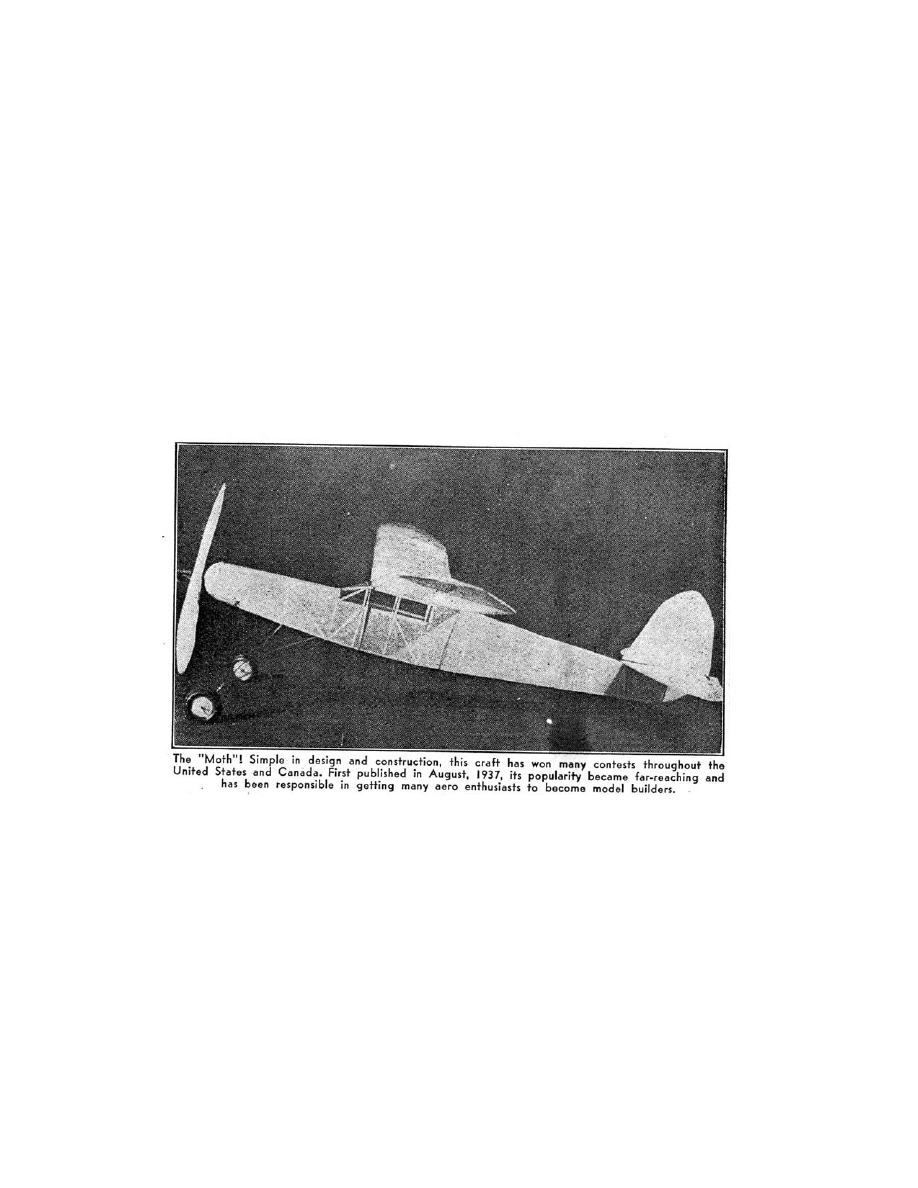
OUTDOOR CABIN SHIPS seem possessed of a certain
popularity that entices even the most indifferent model builder to
at least try building one of its type. This month's presentation is
by no means a "glamour girl" for looks, but we'll guarantee that if
you'll build her, and she can be made in a jiffy, too, she'll turn in
a flying performance that'll dispel such indifference once and for
all.
The only way to become an outdoor flying model fan is to
have a model that consistently turns in good flights and gives
www.ualberta.ca/~khorne
1
Flying Aces–- August, 1941

The Flying Aces “Moth”
you an even chance of winning in any rubber flying model
contest. The FLYING ACES "Moth" is such a ship. (Editor's
Note: Thousands of model builders have built, flown it, and won
—they know!)
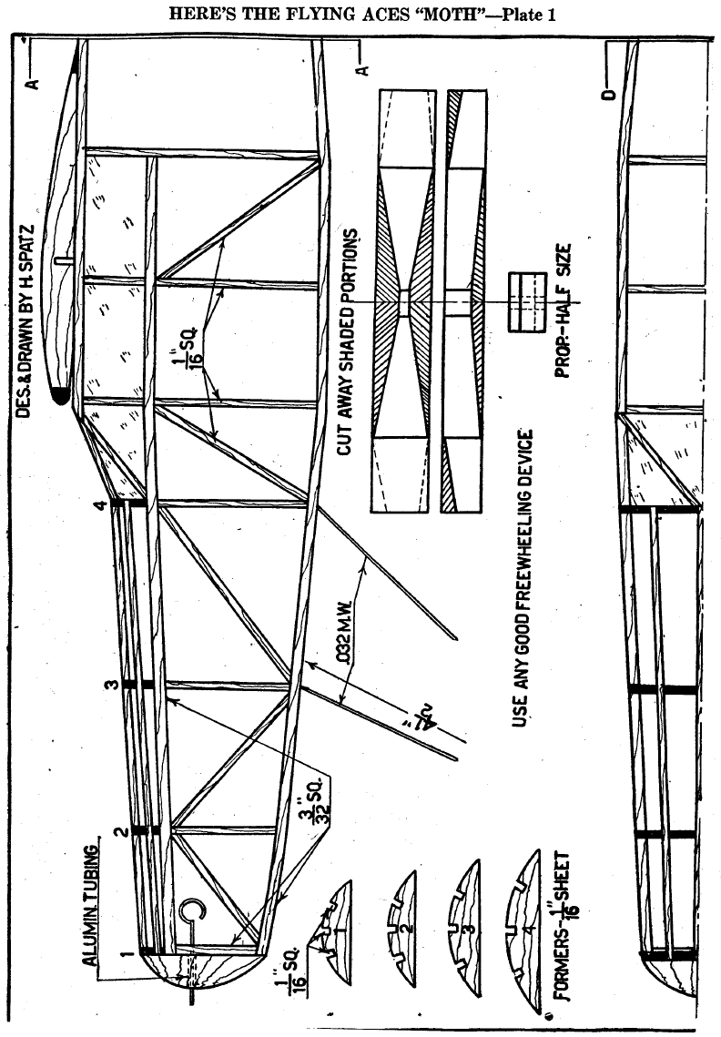
FUSELAGE CONSTRUCTION
THE FIRST STEP is to join Plates 1 and 3 at A-A. The
fuselage is constructed of 1/16" sq, medium hard balsa,
excepting the longerons and such members as are marked
otherwise on the plan. These are 3/32" sq. medium balsa.
Make sure that the longerons all have the same degree of
hardness, or the body won't be straight. Build both sides and
don't use too much glue—just enough to keep the members
together. When the sides are made, glue in the top members,
the size of which can be obtained by doubling those on the plan.
Be sure to get these straight.
Cut formers 1-4 from 1/16" sheet balsa and affix in their
respective places. Cement the 1/16" sq. stringers in place and
put in the two windshield pieces. Next, take a block of ½” by 1
¼” by 1 ¼” balsa and cut it down to fit the nose. Run a piece of
1/16" O.D. aluminum tubing through it and cement. The rear
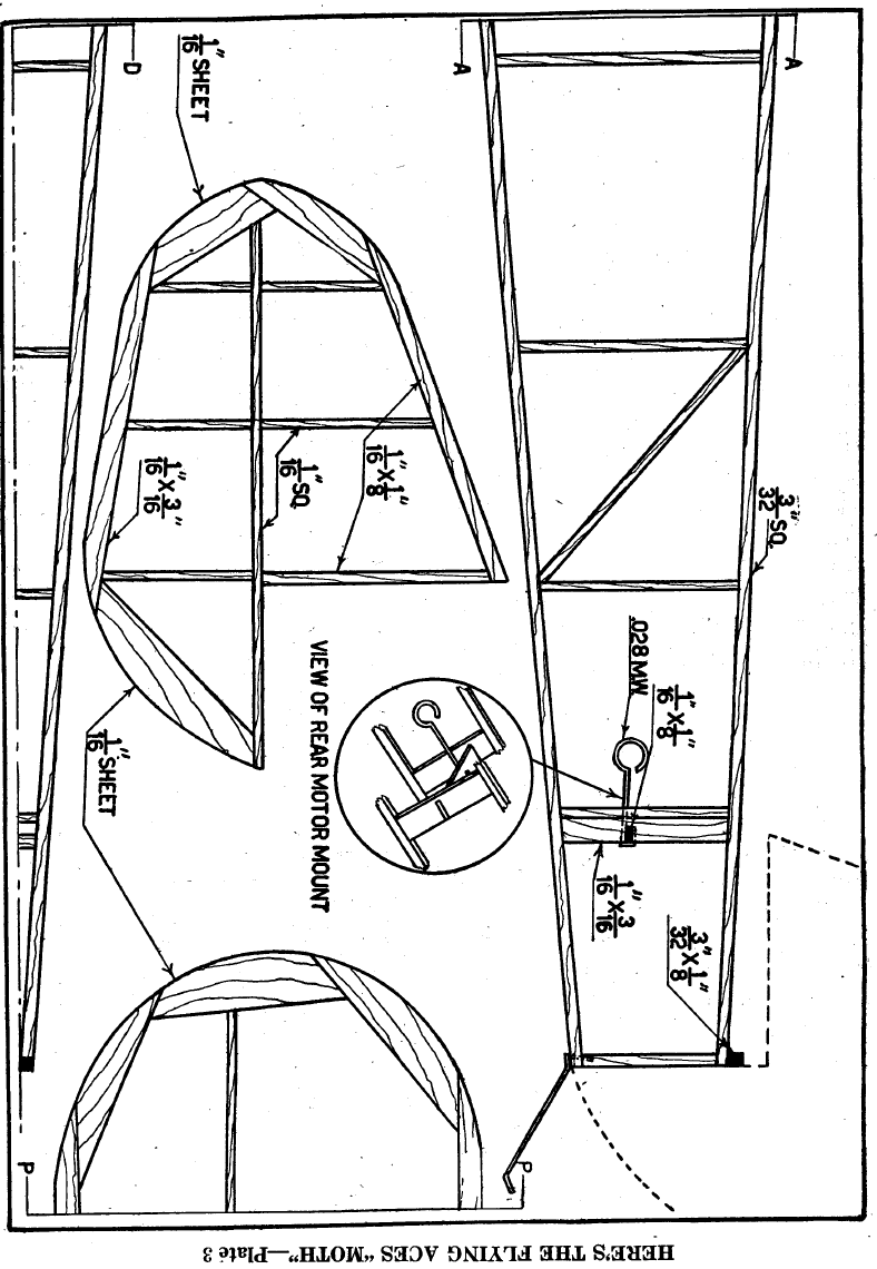
motor mount pieces of 1/16" by 3/16" are glued into the body as
in Plate 3. The crosspiece of 1/16" by 1/8” is cut to fit in the
notches between the mount pieces. The rear hook of .028 music
wire is looped around the crosspiece and cemented securely.
The entire unit is then cemented into place between the mount
pieces. Before attempting to cover the body, go over the entire
fuselage frame and remove all the bumpy particles of dried-up
cement.
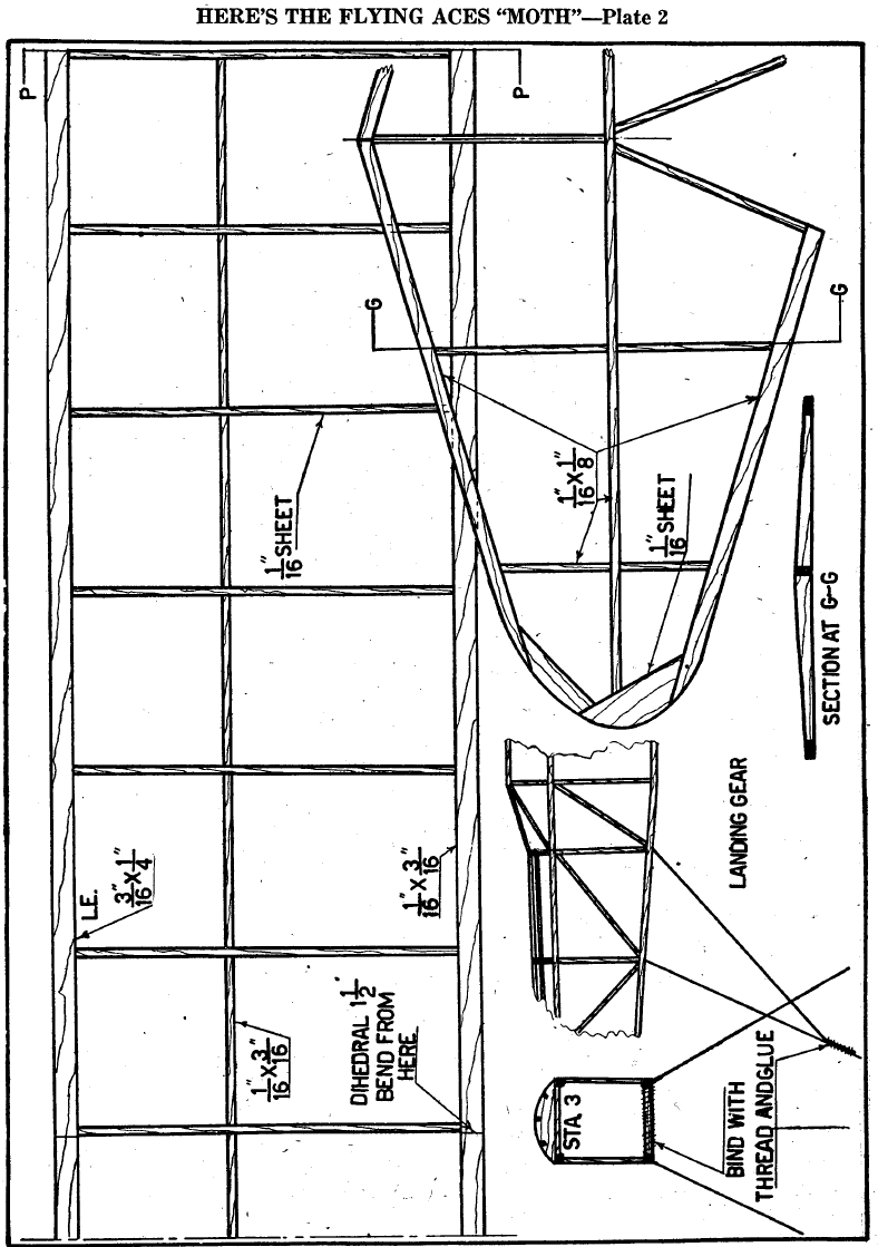
TAIL AND LANDING GEAR
RUDDER PARTS, shown on Plate 3 are made of 1/16" sq.
balsa. The stabilizer is built from the drawings and parts
described on Plate 2. The rib shape is obtained by sanding the
ribs down from the spar as shown.
The landing gear is bent from .034 music wire. The front
struts are 4 ½” long. The axle is bent on the front struts. The
latter are bound to the body at station 3 and cemented. The rear
struts can now be formed. The angle the front struts should
have can be obtained by checking with the plans. The rear
struts can now be measured from station 4 to the axles, then
bound and glued in place. Use a pair of 1 3/8" diameter wheels.
.
www.ualberta.ca/~khorne
2
Flying Aces–- August, 1941

The Flying Aces “Moth”
www.ualberta.ca/~khorne
3
Flying Aces–- August, 1941
MOTOR AND WINGS
CARVE THE prop from a block of balsa measuring ¾” by 1
1/8” by 8 ½”. Any measurements desired may be obtained by
doubling the dimentions on the plan (Plate 1). Cut away the
shaded portions on the plan and carve very carefully.
Sandpaper the prop as smooth as possible. A free wheeling
device should be used for maximum efficiency, the builder
choosing one of his own liking. The prop shaft is bent from .028
wire and slipped through the noseblock after several washers
have been slipped on. For power use 4-6 strands of 1/8” flat.
For the wing, join Plates 2 and 3 at P-P. Lay out the leading
and trailing edges. Make 14 ribs of 1/16" sheet balsa and put
them in the proper places. Cut out the tips and put them in. The
side of the wing shown is the right. To make the other side, take
a sheet of white paper and place it under the plan. Then take a
sheet of carbon paper and place it black-side up under the
sheet of paper and trace its shape.
Before putting in the spar, crack the leading and trailing
edges at the center section shown on Plate 2. There should be
1 ½” dihedral.
ASSEMBLY AND FLYING
WING AND BODY are covered in sections. The tail group
may be covered in two pieces each. Use dope as the adhesive.
Cover the cabin with cellophane. Pin the surfaces down and
spray everything with water to shrink the paper. The builder may
use his own discretion as to what color he will paint his model.
The original was colored yellow.
After everything is dry, give the-ship two coats of dope. Glue
the rudder to the rear of the body, put on the wing and stabilizer
with small rubber bands, and place an incidence block beneath
the stabilizer spar. Next put the prop shaft on the rubber motor,
and you are ready for testing your "sky chariot."
THE END
Document Outline
Wyszukiwarka
Podobne podstrony:
Flying Aces 3806 Phineas Pinkham The Spider and the Flye
Flying Aces 3803 Henry Strucks s Curtiss Tripod Pusher (pd
Flying Dutchman
Flying Ring sample
Fiddlers Green Samolot B 17G Flying Fortress 2003
Legion Condor aces
Orwell Keep the Aspidistra Flying
MS 406 aces (2)
H E Puthoff Synopsis of Unconventional Flying Objects
All Flesh Must Be Eaten Aces High
33 1 3 061 The Flying Burrito Brother's The Gilded Palace of Sin Bob Proehl (pdf)
Heinlein, Robert A No Bands Playing No Flags Flying
Appleton, Victor II Tom Swift Jr 001 Tom Swift and His Flying Lab William Dougherty UC
CS Forester Horatio Hornblower 07 Flying Colours
Niven & Gerrold The Flying Sorcerers
George RR Martin WC 4 Aces Abroad
Just Get Me Flying
Guy Hollingworth Waving The Aces
więcej podobnych podstron