English
Deutsch
Français
Nederlands
Español
Italiano
∂ÏÏËÓÈο
Português
Türkçe
Русский
INSTALLATION MANUAL
For safe and correct use, please read this installation manual thoroughly before installing the air-conditioner
unit.
INSTALLATIONSHANDBUCH
Zum sicheren und ordnungsgemäßen Gebrauch der Klimaanlage das Installationshandbuch gründlich
durchlesen.
MANUEL D’INSTALLATION
Veuillez lire le manuel d’installation en entier avant d’installer ce climatiseur pour éviter tout accident et vous
assurer d’une utilisation correcte.
INSTALLATIEHANDLEIDING
Voor een veilig en juist gebruik moet u deze installatiehandleiding grondig doorlezen voordat u de airconditioner
installeert.
MANUALE DI INSTALLAZIONE
Per un uso sicuro e corretto, leggere attentamente questo manuale di installazione prima di installare il condizionatore
d’aria.
MANUAL DE INSTALACIÓN
Para un uso seguro y correcto, lea detalladamente este manual de instalación antes de montar la unidad de
aire acondicionado.
E°XEIPI¢IO O¢H°IøN E°KATA™TA™H™
°È· ·ÛÊ¿ÏÂÈ· Î·È ÛˆÛÙ‹ ¯Ú‹ÛË, ·Ú·Î·Ï›ÛÙ ‰È·‚¿ÛÂÙ ÚÔÛ¯ÙÈο ·˘Ùfi ÙÔ ÂÁ¯ÂÈÚ›‰ÈÔ ÂÁηٿÛÙ·Û˘
ÚÈÓ ·Ú¯›ÛÂÙ ÙËÓ ÂÁηٿÛÙ·ÛË Ù˘ ÌÔÓ¿‰·˜ ÎÏÈÌ·ÙÈÛÌÔ‡.
MANUAL DE INSTALAÇÃO
Para segurança e utilização correctas, leia atentamente este manual de instalação antes de instalar a unidade
de ar condicionado.
MONTAJ ELK‹TABI
Emniyetli ve do¤ru biçimde nas›l kullan›laca¤›n› ö¤renmek için lütfen klima cihaz›n› monte etmeden önce bu
elkitab›n› dikkatle okuyunuz.
РУКОВОДСТВО ПО УСТАНОВКЕ
Для осторожного и правильного использования прибора необходимо тщательно ознакомиться с данным
руководством по установке до выполнения установки кондиционера.
FOR INSTALLER
FÜR INSTALLATEURE
POUR L’INSTALLATEUR
VOOR DE INSTALLATEUR
PER L’INSTALLATORE
PARA EL INSTALADOR
PARA O INSTALADOR
°π∞ ∞À∆√¡ ¶√À ∫∞¡∂π ∆∏¡ ∂°∫∞∆∞™∆∞™∏
MONTÖR ‹Ç‹N
ДЛЯ УСТАНОВИТЕЛЯ
Air-Conditioners For Building Application
INDOOR UNIT
PLFY-P·VCM-E
For use with the R410A, R407C & R22
Bei Verwendung von R410A, R407C & R22
A utiliser avec le R410A, R407C et le R22
Bij gebruik van R410A, R407C & R22
Para utilizar con el R410A, R407C y el R22
Uso del refrigerante R410A, R407C e R22
°È· ¯Ú‹ÛË ÌÂ Ù·
R410A, R407C Î·È R22
Para utilizaçao com o R410A, R407C e o R22
R410A, R407C ve R22 ile beraber kullanmak için
Для использования с моделями R410A, R407С и R22
2
s Before installing the unit, make sure you read all the “Safety precau-
tions”.
s Please report to your supply authority or obtain their consent before
connecting this equipment to the power supply system.
Warning:
Describes precautions that must be observed to prevent danger of injury or
death to the user.
Caution:
Describes precautions that must be observed to prevent damage to the unit.
After installation work has been completed, explain the “Safety Precautions,” use,
and maintenance of the unit to the customer according to the information in the Op-
eration Manual and perform the test run to ensure normal operation. Both the Instal-
lation Manual and Operation Manual must be given to the user for keeping. These
manuals must be passed on to subsequent users.
Contents
Warning:
• Ask the dealer or an authorized technician to install the air conditioner.
• Install the unit at a place that can withstand its weight.
• Use the specified cables for wiring.
• Use only accessories authorized by Mitsubishi Electric and ask the dealer or
an authorized technician to install them.
• Do not touch the heat exchanger fins.
• Install the air conditioner according to this Installation Manual.
• Have all electric work done by a licensed electrician according to local regu-
lations.
• If the air conditioner is installed in a small room, measures must be taken to
prevent the refrigerant concentration from exceeding the safety limit even if
the refrigerant should leak.
• The cut face punched parts may cause injury by cut, etc. The installers are
requested to wear protective equipement such as gloves, etc.
1. Safety precautions ................................................................................... 2
2. Installing the indoor unit ........................................................................... 2
3. Refrigerant pipe and drain pipe ............................................................... 4
4. Electrical work .......................................................................................... 6
5. Installing the grille .................................................................................... 7
6. Test run (Fig. 6-1) ..................................................................................... 9
1. Safety precautions
: Indicates an action that must be avoided.
: Indicates that important instructions must be followed.
: Indicates a part which must be grounded.
: Indicates that caution should be taken with rotating parts.
: Indicates that the main switch must be turned off before servicing.
: Beware of electric shock.
: Beware of hot surface.
ELV
: At servicing, please shut down the power supply for both the Indoor and
Outdoor Unit.
Warning:
Carefully read the labels affixed to the main unit.
Caution:
• Do not use the existing refrigerant piping, when use R410A or R407C refrig-
erant.
• Use ester oil, either oil or alkylbenzene (small amount) as the refrigerator oil
to coat flares and flange connections, when use R410A or R407C refrigerant.
• Do not use the air conditioner where food, pets, plants, precision instruments,
or artwork are kept.
• Do not use the air conditioner in special environments.
• Ground the unit.
• Install an leak circuit breaker, as required.
• Use power line cables of sufficient current carrying capacity and rating.
• Use only a circuit breaker and fuse of the specified capacity.
• Do not touch the switches with wet fingers.
• Do not touch the refrigerant pipes during and immediately after operation.
• Do not operate the air conditioner with the panels and guards removed.
• Do not turn off the power immediately after stopping operation.
2. Installing the indoor unit
2.1. Check the indoor unit accessories (Fig. 2-1)
The indoor unit should be supplied with the following accessories.
Accessory name
Q’ty
1
Installation template
1
2
Washers (with insulation)
4
Washers (without insulation)
4
3
Pipe cover (for refrigerant piping joint)
small diameter (liquid)
1
large diameter (gas)
1
4
Band (large)
6
Band (small)
2
5
Screw with washer (M5 × 25) for mounting grille
4
6
Drain socket
1
7
Insulation
1
Fig. 2-1
1
2
3
4
6
5
7
3
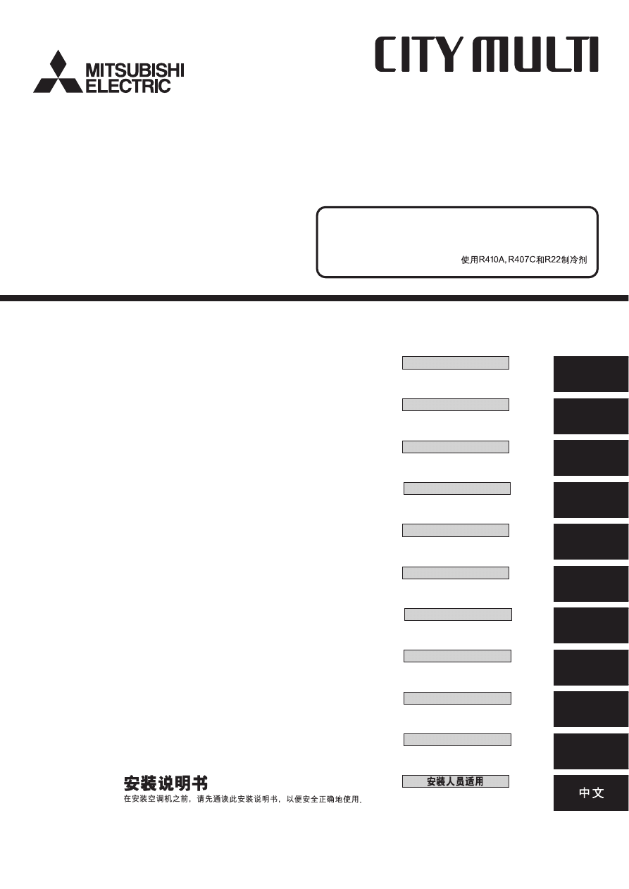
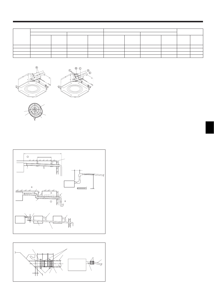
2.2. Ceiling openings and suspension bolt installation
locations (Fig. 2-2)
• Using the installation template (top of the package) and the gauge (supplied as an
accessory with the grille), make an opening in the ceiling so that the main unit can
be installed as shown in the diagram. (The method for using the template and the
gauge are shown.)
* Before using, check the dimensions of template and gauge, because they change
due to fluctuations of temperature and humidity.
* The dimensions of ceiling opening can be regulated within the range shown in
following diagram; so center the main unit against the opening of ceiling, ensur-
ing that the respective opposite sides on all sides of the clearance between
them becomes identical.
• Use M10 (3/8") suspension bolts.
* Suspension bolts are to be procured at the field.
• Install securely, ensuring that there is no clearance between the ceiling panel &
grille, and between the main unit & grille.
2. Installing the indoor unit
A Outer side of main unit
B Bolt pitch
C Ceiling opening
D Outer side of Grille
E Grille
F Ceiling
G Min. 500 mm (Entire periphery)
If setting the maintenance space for G, be
sure to leave is a minimum of 700 mm.
H Maintenance space
I Fresh air intake
J Angle
K Electric component box
* Note that the space between ceiling panel of the unit and ceiling slab and etc must be 10 to
15 mm to be left.
* Leave the maintenance space at the electric component box end.
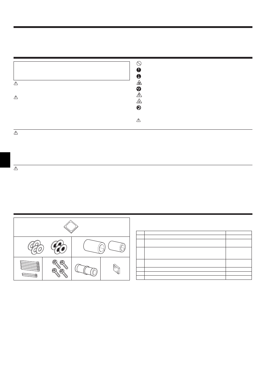
2.3. Installation of duct (in case of fresh air intake)
(Fig. 2-3)
Caution:
Linkage of duct fan and air conditioner
ln case that a duct fan is used, be sure to make it linked with the air conditioner
when outside air is taken.
Do not run the duct fan only. It can cause dew drop.
Making a duct flange (prepared locally)
• The shape of duct flange shown left is recommended.
Installation of duct flange
• Cut out the cutout hole. Do not knock it out.
• Install a duct flange to the cutout hole of the indoor unit with three 4 × 10 tapping
screws which should be prepared locally.
Installation of duct (should be prepared locally)
• Prepare a duct of which inner diameter fits into the outer diamete of the duct flange.
• In case that the environment above the ceiling is high temperature and high humid-
ity, wrap the duct in a heat insulate to avoid causing dew drop on the wall.
A Duct flange recommended shape
(Thickness:0.8 or more)
B 3-ø5 hole
C Detail drawing of fresh air intake
D Indoor unit
E Ceiling surface
F 3-ø2.8 Burring hole
G ø73.4 cutout hole
H Duct flange (Prepared locally)
I 4 × 10 Tapping screw (Prepared locally)
J Duct
2.4. Suspension structure (Give site of suspension
strong structure) (Fig. 2-4)
• The ceiling work differs according to the construction of the building. Buidling con-
structors and interior decorators should be consulted for details.
(1) Extent of ceiling removal: The ceiling must be kept completely horizontal and the
ceiling foundation (framework: wooden slats and slat holders) must be reinforced
in order to protect the ceiling from vibration.
(2) Cut and remove the ceiling foundation.
(3) Reinforce the ends of the ceiling foundation where it has been cut and add ceiling
foundation for securing the ends of the ceiling board.
(4) When installing the unit on a slanting ceiling, interlock a pillow between the ceiling
and the grille and set so that the unit is installed horizontally.
1 Wooden structures
• Use tie beams (single storied houses) or second floor beams (two story houses) as
reinforcing members.
• Wooden beams for suspending air conditioners must be sturdy and their sides
must be at least 6 cm long if the beams are separated by not more than 90 cm and
their sides must be at least 9 cm long if the beams are separated by as much as
180 cm. The size of the suspension bolts should be ø10 (3/8"). (The bolts do not
come with the unit.)
2 Ferro-concrete structures
Secure the suspension bolts using the method shown, or use steel or wooden hang-
ers, etc. to install the suspension bolts.
A Unit
B Grille
C Pillow
D Ceiling
E Rafter
F Beam
G Roof beam
H Use inserts rated at 100-150 kg
each (procure locally)
I Suspension bolts M10 (3/8") (procure
locally)
J Steel reinforcing rod
A
B
C
J
H
I
D
E
F G
*B
*B
1
2
Fig. 2-4
Fig. 2-2
B
30
120
120
20
75
100
70
15
G
E
D
F
120
120
92
25
+5
27
0
208
100
Fig. 2-3
D
H
I
J
A
(mm)
C
(mm)
*B: Suspension bolt pitch (see Fig. 2-2 B for details)
4
3. Refrigerant pipe and drain pipe
3.1. Refrigerant and drainage piping locations of indoor
unit (Fig. 3-1)
A Drain pipe
B Ceiling
C Grille
D Refrigerant pipe (liquid)
E Refrigerant pipe (gas)
F Water supply inlet
G Main unit
Fig. 3-1
A Flare cutting dimensions
Copper pipe O.D.
Flare dimensions
(mm)
øA dimensions (mm)
ø6.35
8.7 - 9.1
ø9.52
12.8 - 13.2
ø12.7
16.2 - 16.6
ø15.88
19.3 - 19.7
ø19.05
22.9 - 23.3
90
°
±0.5
°
ø
A
R0.4~R0.8
A
45°±2°
B
Fig. 3-2
C
B
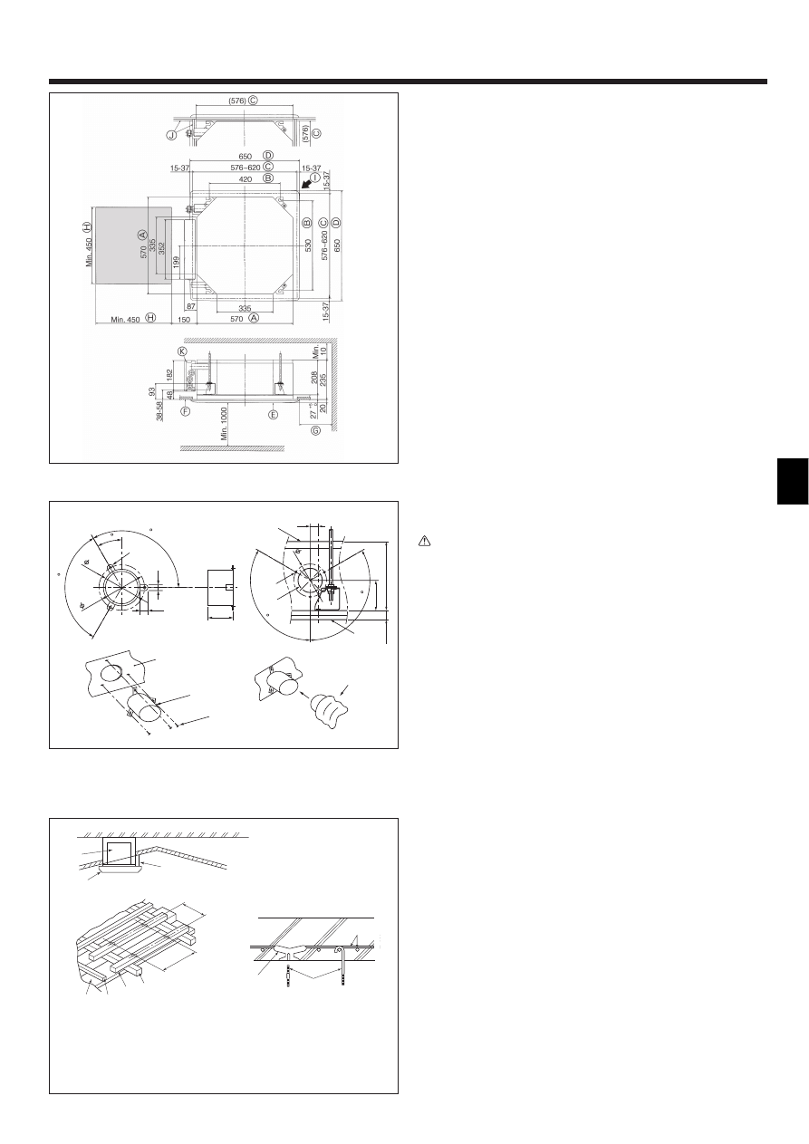
2. Installing the indoor unit
A Suspension bolt (Procure locally)
B Ceiling
C Nut (Procure locally)
D Washer (with insulation) (Accessory)
27
93
+5 0
A
B
A
C
D
E
F
C
B
G
Min. 30
Fig. 2-5
2.5. Unit suspension procedures (Fig. 2-5)
Suspend the main unit as shown in the diagram.
1. In advance, set the parts onto the suspension bolts in the order of the washers
(with insulation), washers (without insulation) and nuts (double).
• Fit the washer with cushion so that the insulation faces downward.
• In case of using upper washers to suspend the main unit, the lower washers
(with insulation) and nuts (double) are to be set later.
2. Lift the unit to the proper height of the suspension bolts to insert the mounting
plate between washers and then fasten it securely.
3. When the main unit can not be aligned against the mounting hole on the ceiling, it
is adjustable owing to a slot provided on the mounting plate. (Fig. 2-6)
• Make sure that step A is performed within 27-32 mm. Damage could result by
failing to adhere to this range.
2.6. Confirming the position of main unit and tighten-
ing the suspension bolts (Fig. 2-7)
• Using the gauge attached to the grille, ensure that the bottom of the main unit is
properly aligned with the opening of the ceiling. Be sure to confirm this, otherwise
condensation may form and drip due to air leakage etc.
• Confirm that the main unit is horizontally levelled, using a level or a vinyl tube filled
with water.
• After checking the position of the main unit, tighten the nuts of the suspension bolts
securely to fasten the main unit.
• The installation template can be used as a protective sheet to prevent dust from
entering the main unit when the grilles are left unattached for a while or when the
ceiling materials are to be lined after installation of the unit is finished.
* As for the details of fitting, refer to the instructions given on the Installation template.
C
D
B
A
A Main unit
B Ceiling
C Installation template (Accessory)
D Screw with washer (Accessory)
Fig. 2-7
Fig. 2-6
E Mounting plate
F Washer (without insulation) (Accessory)
G Check using the Installation gauge
A Main unit
B Ceiling
C Gauge (Grille accessory)
D Ceiling opening dimensions
As viewed from A
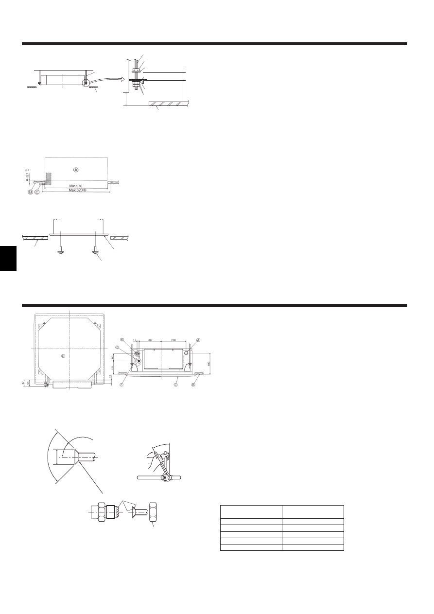
3.2. Connecting pipes (Fig. 3-2)
• When commercially available copper pipes are used, wrap liquid and gas pipes
with commercially available insulation materials (heat-resistant to 100 °C or more,
thickness of 12 mm or more).
• The indoor parts of the drain pipe should be wrapped with polyethylene foam insu-
lation materials (specific gravity of 0.03, thickness of 9 mm or more).
• Apply thin layer of refrigerant oil to pipe and joint seating surface before tightening
flare nut.
• Use two wrenches to tighten piping connections.
• Use refrigerant piping insulation provided to insulate indoor unit connections. Insu-
late carefully.
5
Fig. 3-3
3. Refrigerant pipe and drain pipe
3.4. Drainage piping work (Fig. 3-4)
• Use VP25 (O.D. ø32 (1-1/4”) PVC TUBE) for drain piping and provide 1/100 or
more downward slope.
• Be sure to connect the piping joints using a polyvinyl type adhesive.
• Observe the figure for piping work.
• Use the included drain hose to change the extraction direction.
1 Correct piping
2 Wrong piping
A Insulation (9 mm or more)
B Downward slope (1/100 or more)
C Support metal
K Air bleeder
L Raised
M Odor trap
Grouped piping
D O. D. ø32 PVC TUBE
E Make it as large as possible
F Indoor unit
G Make the piping size large for grouped piping.
H Downward slope (1/100 or more)
I O. D. ø38 PVC TUBE for grouped piping.
(9 mm or more insulation)
J Up to 500 mm
1. Connect the drain socket (supplied with the unit) to the drain port. (Fig. 3-5)
(Affix the tube using PVC adhesive then secure it with a band.)
2. Install a locally purchased drain pipe (PVC pipe, O.D. ø32).
(Affix the pipe using PVC adhesive then secure it with a band.)
3. Insulate the tube and pipe. (PVC pipe, O.D. ø32 and socket)
4. Check that drain flows smoothly.
5. Insulate the drain port with insulating material, then secure the material with a
band. (Both insulating material and band are supplied with the unit.)
A Unit
B Insulating material
C Band (large)
D Drain port (transparent)
E Insertion margin
F Matching
G Drain pipe (O.D. ø32 PVC TUBE)
H Insulating material (purchased locally)
I Transparent PVC pipe
J O.D. ø32 PVC TUBE (Slope 1/100 or more)
K Band (small)
L Drain socket
Max. 20m
1.5–2m
A
B
C
B
M
L
K
D
E
D
H
I
G
D
F
F
F
Max. 15cm
J
F
Fig. 3-4
Fig. 3-5
B Refrigerant pipe sizes & Flare nut tightening torque
Flare nut O.D.
Liquid
Gas
pipe
pipe
(mm)
(mm)
17
26
22
29
22
29
22
36
C Apply refrigerating machine oil over the entire flare seat surface.
* Use the provided flare nut for the following pipes: Liquid pipe of P50, P100, P125, and gas pipe of P50.
R410A
Liquid pipe
Gas pipe
Tightening
Tightening
Pipe size
torque
Pipe size
torque
(mm)
(N.m)
(mm)
(N.m)
ODø6.35 (1/4”)
14 - 18
ODø12.7 (1/2”)
49 - 61
ODø6.35 (1/4”)
34 - 42
ODø12.7 (1/2”)
68 - 82
ODø9.52 (3/8”)
34 - 42
ODø15.88 (5/8”)
68 - 82
ODø9.52 (3/8”)
34 - 42
ODø15.88 (5/8”)
100 - 120
R407C or R22
Liquid pipe
Gas pipe
Tightening
Tightening
Pipe size
torque
Pipe size
torque
(mm)
(N.m)
(mm)
(N.m)
ODø6.35 (1/4”)
14 - 18
ODø12.7 (1/2”)
49 - 61
ODø9.52 (3/8”)
34 - 42*
ODø15.88 (5/8”)
68 - 82*
ODø9.52 (3/8”)
34 - 42
ODø15.88 (5/8”)
68 - 82
ODø9.52 (3/8”)
34 - 42
ODø19.05 (3/4”)
100 - 120*
J
H
I
B,C
F
G
G
11
30
30
30
B
A
C
K
F
L
H
D
E
E
I
J
C,K
(mm)
P20/25/32/40
P50
P63/80
P100/125
3.3. Indoor unit (Fig. 3-3)
Heat insulation for refrigerant pipes:
1 Wrap the enclosed large-sized pipe cover around the gas pipe, making sure that
the end of the pipe cover touches the side of the unit.
2 Wrap the enclosed small-sized pipe cover around the liquid pipe, making sure
that the end of the pipe cover touches the side of the unit.
3 Secure both ends of each pipe cover with the enclosed bands. (Attach the bands
20 mm from the ends of the pipe cover.)
• After connecting the refrigerant piping to the indoor unit, be sure to test the pipe
connections for gas leakage with nitrogen gas. (Check that there is no refrigerant
leakage from the refrigerant piping to the indoor unit.)
A Refrigerant pipe and insulating material
(Procure locally)
B Pipe cover (large) (Accessory)
C Pipe cover (small) (Accessory)
D Refrigerant pipe (gas)
E Refrigerant pipe (liquid)
F Band (Accessory)
g Cross-sectional view of connection
H Refrigerant pipe
I Insulating material
J Squeeze
6
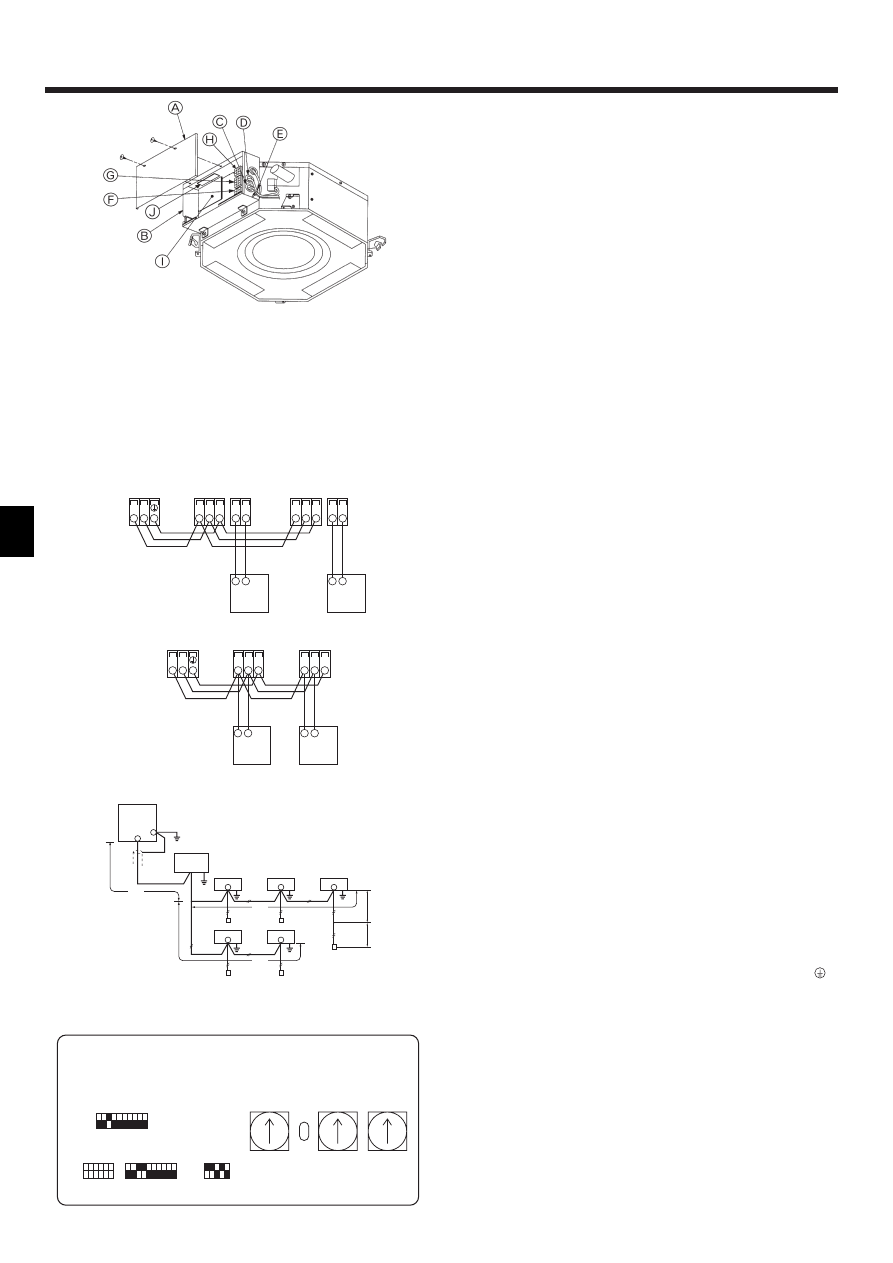
4. Electrical work
4.1. Indoor unit (Fig. 4-1)
1.Remove 2 screws to detach the electric component cover.
2.Route each cable through the wiring intake into the electric component box. (Pro-
cure power supply cable and control cable locally.)
3.Securely connect the power supply cable and control cable to the terminal blocks.
4.Secure the cables with clamps outside the electric component box.
5.Attach the electric component cover as it was.
• Do not allow slackening of the terminal screws.
• Always install earth.
(Earth cable dia: Thicker than 1.6 mm)
• Fix power supply cable and control cable to electric component box by using buffer
bushing for tensile forse. (PG connection or the like.)
s
s
s
s
s Selecting non-fuse breaker (NF) or earth leakage breaker (NV).
A means for the disconnection of the supply with an isolation switch, or similar de-
vice, in all active conductors shall be incorporated in the fixed wiring.
Power supply wiring
• Power supply codes of appliance shall not be lighter than design 245 IEC 53 or 227
IEC 53.
• A switch with at least 3 mm contact separation in each pole shall be provided by the
air conditioner installation.
Power cable size: more than 1.5 mm
2
.
Fig. 4-1
Fig. 4-2
1
2
A
A
C
TB5
TB15 TB5
TB15
S
M1 M2
S
M1 M2
B
TB3
M1 M2
2
1
C
2
1
A
A
C
TB5
TB5
S
M1 M2
S
M1 M2
C
B
TB3
M1 M2
4.2. Connecting remote controller, indoor and outdoor
transmission cables (Fig. 4-2)
• Connect indoor unit TB5 and outdoor unit TB3. (Non-polarized 2-wire)
The “S” on indoor unit TB5 is a shielding wire connection. For specifications about
the connecting cables, refer to the outdoor unit installation manual.
• Install a remote controller following the manual supplied with the remote controller.
• Connect the remote controller’s transmission cable within 10 m using a 0.75 mm
2
core cable. If the distance is more than 10 m, use a 1.25 mm
2
junction cable.
1 MA Remote controller
• Connect the “1” and “2” on indoor unit TB15 to a MA remote controller. (Non-polar-
ized 2-wire)
• DC 9 to 13 V between 1 and 2 (MA remote controller)
2 M-NET Remote controller
• Connect the “M1” and “M2” on indoor unit TB5 to a M-NET remote controller. (Non-
polarized 2-wire)
• DC 24 to 30 V between M1 and M2 (M-NET remote controller)
A Terminal block for indoor transmission cable
B Terminal block for outdoor transmission cable
C Remote controller
Constraints on transmission cable (Fig. 4-3)
Longest wiring length (L
1
+L
2
+L
4
or L
1
+L
3
or L
2
+L
3
+L
4
): less than 200 m
Length between indoor unit and remote controller (R): within 10 m
G Outdoor unit
H Earth
I BC controller
J Indoor unit
K M-NET Remote controller
L Non-polarized 2-wire
Note:
*1 Put the transmission cable earth via the outdoor unit’s earth terminal
to
the ground.
*2 If the remote controller cable exceeds 10 m, use a 1.25 mm
2
diameter cable
over the exceeded portion, and add that exceeded portion to within 200 m.
*3 The BC controller is required only for simultaneous cooling and heating
series R2.
4.3. Setting addresses (Fig. 4-4)
(Be sure to operate with the main power turned OFF.)
• There are two types of rotary switch setting available: setting addresses 1 to 9 and
over 10, and setting branch numbers.
Fig. 4-3
Fig. 4-4
G
I
J
J
J
K
K
K
K
J
J
L
K
H
*1
*3
L1
L2
L4
r
L3
*2
A Electric component cover
B Electric component box
C Entry for power supply cable
D Entry for control cable
E Cable clamp
F Power supply terminals
G Transmission terminals
H MA Remoto controller terminal
I Indoor controller
J Power board
123456
ON
OFF
ON
OFF
SW1
SW2
SW3
SW4
12345
ON
OFF
12345678910
12345678910
SW11
0
SW12
0
SW14
0
CONNECTION
No.
3RD
DIGIT
2ND
DIGIT
1ST
DIGIT
7
4. Electrical work
4.4. Sensing room temperature with the built-in sen-
sor in a remote controller
If you want to sense room temperature with the built-in sensor in a remote controller,
set SW1-1 on the control board to “ON”. The setting of SW1-7 and SW1-8 as neces-
sary also makes it possible to adjust the air flow at a time when the heating ther-
mometer is OFF.
4.5. Types of control cables
1. Wiring transmission cables: Shielding wire CVVS or CPEVS
• Cable diameter : More than 1.25 mm
2
2. M-NET Remote control cables
Kind of remote control cable Shielding wire MVVS
Cable diameter
More than 0.5 to 1.25 mm
2
Remarks
When 10 m is exceeded, use cable with the same
specifications as transmission line wiring.
3. MA Remote control cables
Kind of remote control cable 2-core cable (unshielded)
Cable diameter
0.3 to 1.25 mm
2
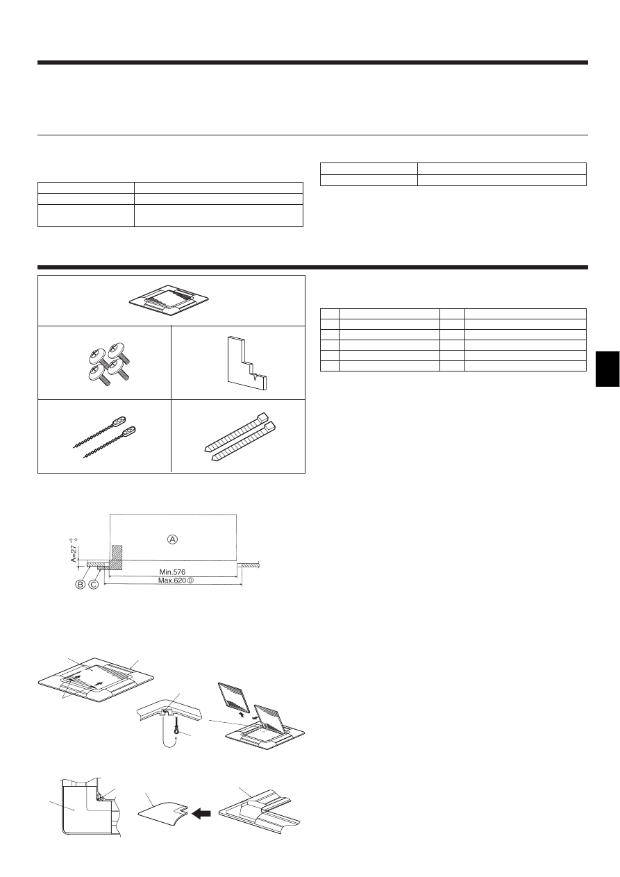
5. Installing the grille
5.1. Check the grille accessories (Fig. 5-1)
• The grille should be supplied with the following accessories.
Accessory name
Q’ty
Remark
1
Grille
1
650 × 650 (mm)
2
Screw with washer
4
M5 × 0.8 × 25 (mm)
3
Gauge
1
4
Fastener
2
5
Band
2
Fig. 5-1
1
4
5
2
3
Fig. 5-3
B
A
C
1
1
D
E
2
F
G
F
B
1
Fig. 5-4
5.2. Preparing to attach the grille (Fig. 5-2)
• With the gauge supplied with this kit, adjust and check the positioning of the unit
relative to the ceiling. If the unit is not properly positioned in the ceiling, there may
be air leaks, condensation may form, or the up/down vanes may not operate cor-
rectly.
• Make sure that the opening in the ceiling is within the following tolerances:
576 × 576 - 620 × 620
• Make sure that step A is performed within 27-32 mm. Damage could result by fail-
ing to adhere to this range.
A Main unit
B Ceiling
C Gauge (Accessory)
D Ceiling opening dimensions
5.2.1. Removing the intake grille (Fig. 5-3)
• Slide the levers in the direction indicated by the arrow 1 to open the intake grille.
• Unlatch the hook that secures the grille.
* Do not unlatch the hook for the intake grille.
• With the intake grille in the “open” position, remove the hinge of the intake grille
from the grille as indicated by the arrow 2.
5.2.2. Removing the corner panel (Fig. 5-4)
• Remove the screw from the corner of the corner panel. Slide the corner panel as
indicated by the arrow 1 to remove the corner panel.
A Intake grille
B Grille
C Intake grille levers
D Grille hook
Fig. 5-2
E Hole for the grille’s hook
F Corner panel
G Screw
8
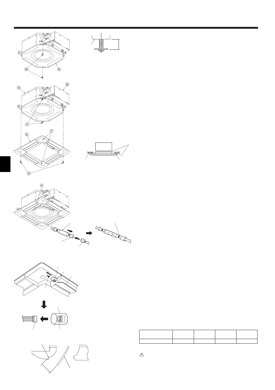
5.3. Installing the grille
• Please pay attention because there is a restriction in the attachment position of the
grille.
5.3.1. Preparations (Fig. 5-5)
• Install the two enclosed screws with washer in the main unit (at the corner refriger-
ant pipe area and at the opposite corner) as shown in the diagram.
A Main unit
B Detailed diagram of installed screw with washer (accessory).
15~20
A
B
(mm)
Fig. 5-5
5.3.2. Temporary installation of the grille (Fig. 5-6)
• Align the electric component box of the main unit and the receiver of the grille, and
then temporarily secure the grille using the bell shaped holes.
* Make sure that the lead wiring of the grille does not get pinched between the
grille and the main unit.
A Main unit
B Electric component box
C Screw with washer (for temporary use)
D Screw with washer (Accessory)
E Grille
F Bell shaped hole
5.3.3. Securing the grille (Fig. 5-7)
• Secure the grille to the main unit by tightening the previously installed two screws
(with captive washer) as well as the two remaining screws (with captive washer).
* Make sure that there are no gaps between the main unit and the grille or the
grille and the ceiling.
A Ceiling
B Main unit
C Grille
D Make sure that there are no gaps.
A
C
D
B
Fig. 5-6
Fig. 5-7
5. Installing the grille
C
D
B
E
Fig. 5-8
5.4. Locking the up/down airflow direction (Fig. 5-9)
The vanes of the unit can be set and locked in up or down orientations depending
upon the environment of use.
• Set according to the preference of the customer.
The operation of the fixed up/down vanes and all automatic controls cannot be
performed using the remote controller. In addition, the actual position of the vanes
may differ from the position indicated on the remote controller.
1 Turn off the main power switch.
Injuries and or an electrical shock may occur while the fan of the unit is rotating.
2 Disconnect the connector for the vane motor of the vent that you want to lock.
(While pressing the button, remove the connector in the direction indicated by the
arrow as shown in the diagram.) After removing the connector, insulate it with
tape.
3 To adjust the desired airflow direction, slowly move the up/down vanes within the
specified range. (Fig. 5-10)
Specified range
Up/down airflow
Horizontal 30° Downward 45° Downward 55° Downward 70°
direction
A (mm)
21
25
28
30
• The vanes can be set between 21 and 30 mm.
Caution:
Do not set the up/down vanes passed the specified range. Condensation could
form on and drop from the ceiling, or the unit could malfunction.
C
B
A
D
B
A
D
Fig. 5-9
A Button
B Vane motor
C Up/down vanes
D Connector
E
F
A
5.3.4. Wire connection (Fig. 5-8)
• Be sure to connect the unit to the connector (white:10-pole/red:9-pole). Next, at-
tach the white glass tube that comes with the main unit so that the tube covers the
connector. Close the opening of the glass tube with the band.
• Make sure that there is no slack in the each lead wire at the fastener on the grille.
A Fastener (Accessory)
B White glass tube
C Connector of the main unit
D Connector of the grille
E Band (Accessory)
E Measurement standard
position of grille
F Up/down vanes
Fig. 5-10
9
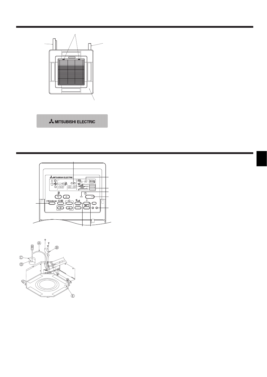
6. Test run (Fig. 6-1)
TIMER SET
PAR-20MAA
ON/OFF
CENTRALLY CONTROLLED
ERROR CODE
CLOCK
ON
OFF
˚C
CHECK
CHECK MODE
FILTER
TEST RUN
FUNCTION
˚C
1Hr.
NOT AVAILABLE
STAND BY
DEFROST
FILTER
CHECK TEST
TEMP.
2
BC
3
4
5
1
A
E
D
1 Press [TEST RUN] button twice → displaying [TEST RUN] on the screen.
2 Press [Selecting operation] button. → Check that wind is blowing out.
3 Press [Fan speed adjustment] button. → Check that the wind speed is changed.
4 Press [Up/down airflow selection] button to change wind direction.
5 Press [ON/OFF] button to clear test run. → Test run stops.
A Lighting in operation
B Displaying inspection code
C Displaying remaining test run time
D Displaying indoor unit’s liquid pipe temperature
E Displaying test run
Note:
• The 2-hour-set timer is activated to automatically stop test run after two hours.
• The remote controller displays the temperature of the indoor unit’s liquid
pipe on the temperature display section during test run.
Fig. 6-1
6.1. Check of drainage (Fig. 6-2)
• During the trial run, ensure the water is being properly drained out and that no
water is leaking from joints.
• Always check this during installation even if the unit is not required to provide cool-
ing/drying at that time.
• Similarly, check the drainage before finishing ceiling installation in a new premises.
(1) Remove the cover of the water supply inlet and add about 1000 cc of water using
a water supply pump etc. During this process, be careful not to spray water into
the drain pump mechanism.
(2) Confirm that water is being drained out through the drainage outlet, after switch-
ing over from remote control mode to trial run mode.
(3) After checking the drainage, ensure that the cover is replaced and the power
supply is isolated.
(4) After confirming the drainage system is functioning, replace the drain plug.
Fig. 6-2
A Insert the pump end 3 to 5 cm
B Cover of water supply inlet
C About 1000 cc
D Water
E Drain plug
Fig. 5-11
5.5. Installing the intake grille (Fig. 5-11)
• Perform the procedure that is described in “5.2 Preparing to attach the grille” in
reverse order to install the intake grille and the corner panel.
A Refrigerant piping of the main unit
B Drain piping of the main unit
C Corner panel
* Installation in any position is possible.
D Position of the levers on the intake grille when sent from the factory.
* Although the clips can be installed in any of four positions.
5.6. Check
• Make sure that there is no gap between the unit and the grille, or between the grille
and the surface of the ceiling. If there is any gap between the unit and the grille, or
between the grille and the surface of the ceiling, it may cause dew to collect.
• Make sure that the wires have been securely connected.
5. Installing the grille
A
D
B
C
Wyszukiwarka
Podobne podstrony:
BWE04210 PartsList PEFY P20 25 32VML A1 Oct 2004
IM PLFY P VAM E BG79U320H01
25 32 wym płaskie
TEST KLASA 4 - KATECHEZY 25-32, teologia
NIEOR 25-32, Studia, II rok, Chemia nieorganiczna
okrytonasienne rodziny 25-32, Botanika, Rodziny
aksonometria zadania, Rzutowanie 25 32
25 -32, 5 rok prawo, 5 rok, rodzinne, rodzinne, egzamin rodzinne
Rzutowanie 25 32
BWE0333Z PartsList PLFY P20 125VLMD Dec 2003
BWE03020 PartsList PLFY P20 63VLMD B 2003
skills test units 25 32 b
BWE0316Z PartsList PEFY P20 25 32VML A Jun 2003
24 25 406c pol ed01 2004
akumulator do volvo v70 iii kombi 20 25 t 32 32 awd 30 t6 a
BWE0421A PartsList PEFY P20 25 32VML A1 Jun 2009
IM PLFY P VLMD A WT03272X02
więcej podobnych podstron