
SAP2000
®
Integrated
Finite Element Analysis
and
Design of Structures
CONCRETE DESIGN MANUAL
COMPUTERS &
STRUCTURES
INC.
R
Computers and Structures, Inc.
Berkeley, California, USA
Version 7.4
Revised May 2000

COPYRIGHT
The computer program SAP2000 and all associated documentation are
proprietary and copyrighted products. Worldwide rights of ownership
rest with Computers and Structures, Inc. Unlicensed use of the program
or reproduction of the documentation in any form, without prior written
authorization from Computers and Structures, Inc., is explicitly prohib-
ited.
Further information and copies of this documentation may be obtained
from:
Computers and Structures, Inc.
1995 University Avenue
Berkeley, California 94704 USA
Tel: (510) 845-2177
Fax: (510) 845-4096
E-mail: info@csiberkeley.com
Web: www.csiberkeley.com
© Copyright Computers and Structures, Inc., 1978–2000.
The CSI Logo is a registered trademark of Computers and Structures, Inc.
SAP2000 is a registered trademark of Computers and Structures, Inc.

DISCLAIMER
CONSIDERABLE TIME, EFFORT AND EXPENSE HAVE GONE
INTO THE DEVELOPMENT AND DOCUMENTATION OF
SAP2000. THE PROGRAM HAS BEEN THOROUGHLY TESTED
AND USED. IN USING THE PROGRAM, HOWEVER, THE USER
ACCEPTS AND UNDERSTANDS THAT NO WARRANTY IS EX-
PRESSED OR IMPLIED BY THE DEVELOPERS OR THE DIS-
TRIBUTORS ON THE ACCURACY OR THE RELIABILITY OF
THE PROGRAM.
THIS PROGRAM IS A VERY PRACTICAL TOOL FOR THE DE-
SIGN OF REINFORCED CONCRETE STRUCTURES. HOWEVER,
THE USER MUST THOROUGHLY READ THE MANUAL AND
CLEARLY RECOGNIZE THE ASPECTS OF REINFORCED CON-
CRETE DESIGN THAT THE PROGRAM ALGORITHMS DO NOT
ADDRESS.
THE USER MUST EXPLICITLY UNDERSTAND THE ASSUMP-
TIONS OF THE PROGRAM AND MUST INDEPENDENTLY VER-
IFY THE RESULTS.


Table of Contents
Overview . . . . . . . . . . . . . . . . . . . . . . . . . . . . . . . . . 1
Organization . . . . . . . . . . . . . . . . . . . . . . . . . . . . . . . 2
Recommended Reading . . . . . . . . . . . . . . . . . . . . . . . . . . 3
Design Load Combinations . . . . . . . . . . . . . . . . . . . . . . . . 6
Design and Check Stations . . . . . . . . . . . . . . . . . . . . . . . . 7
Identifying Beams and Columns . . . . . . . . . . . . . . . . . . . . . 8
Design of Beams . . . . . . . . . . . . . . . . . . . . . . . . . . . . . 8
Design of Columns . . . . . . . . . . . . . . . . . . . . . . . . . . . . 9
Effects . . . . . . . . . . . . . . . . . . . . . . . . . . . . . . . . 12
Element Unsupported Lengths . . . . . . . . . . . . . . . . . . . . . 12
Special Considerations for Seismic Loads . . . . . . . . . . . . . . . 14
Choice of Input Units . . . . . . . . . . . . . . . . . . . . . . . . . . 14
CHAPTER III Design for ACI 318-99
Design Load Combinations . . . . . . . . . . . . . . . . . . . . . . . 17
Strength Reduction Factors . . . . . . . . . . . . . . . . . . . . . . . 20
Column Design . . . . . . . . . . . . . . . . . . . . . . . . . . . . . 21
Generation of Biaxial Interaction Surfaces . . . . . . . . . . . . . 21
Check Column Capacity . . . . . . . . . . . . . . . . . . . . . . 23
Determine Factored Moments and Forces. . . . . . . . . . . 23
Determine Moment Magnification Factors . . . . . . . . . . 23
Determine Capacity Ratio . . . . . . . . . . . . . . . . . . . 25
Design Column Shear Reinforcement . . . . . . . . . . . . . . . 26
Determine Section Forces . . . . . . . . . . . . . . . . . . . 27
i

Determine Concrete Shear Capacity . . . . . . . . . . . . . 28
Determine Required Shear Reinforcement . . . . . . . . . . 30
Beam Design. . . . . . . . . . . . . . . . . . . . . . . . . . . . . . . 30
Design Beam Flexural Reinforcement . . . . . . . . . . . . . . . 31
Design Beam Shear Reinforcement. . . . . . . . . . . . . . . . . 38
Determine Shear Force and Moment . . . . . . . . . . . . . 38
Determine Concrete Shear Capacity . . . . . . . . . . . . . 40
Determine Required Shear Reinforcement . . . . . . . . . . 40
CHAPTER IV Design for AASHTO LRFD 1997
Design Load Combinations . . . . . . . . . . . . . . . . . . . . . . . 46
Strength Reduction Factors . . . . . . . . . . . . . . . . . . . . . . . 47
Column Design . . . . . . . . . . . . . . . . . . . . . . . . . . . . . 47
Generation of Biaxial Interaction Surfaces . . . . . . . . . . . . . 48
Check Column Capacity . . . . . . . . . . . . . . . . . . . . . . 50
Determine Factored Moments and Forces. . . . . . . . . . . 50
Determine Moment Magnification Factors . . . . . . . . . . 51
Determine Capacity Ratio . . . . . . . . . . . . . . . . . . . 52
Design Column Shear Reinforcement . . . . . . . . . . . . . . . 53
Determine Section Forces . . . . . . . . . . . . . . . . . . . 54
Determine Concrete Shear Capacity . . . . . . . . . . . . . 55
Determine Required Shear Reinforcement . . . . . . . . . . 55
Beam Design. . . . . . . . . . . . . . . . . . . . . . . . . . . . . . . 59
Design Beam Flexural Reinforcement . . . . . . . . . . . . . . . 59
Determine Factored Moments . . . . . . . . . . . . . . . . . 59
Determine Required Flexural Reinforcement . . . . . . . . . 60
Design Beam Shear Reinforcement. . . . . . . . . . . . . . . . . 66
Determine Shear Force and Moment . . . . . . . . . . . . . 66
Determine Concrete Shear Capacity . . . . . . . . . . . . . 67
Determine Required Shear Reinforcement . . . . . . . . . . 67
Design Load Combinations . . . . . . . . . . . . . . . . . . . . . . . 74
Strength Reduction Factors . . . . . . . . . . . . . . . . . . . . . . . 74
Column Design . . . . . . . . . . . . . . . . . . . . . . . . . . . . . 75
Generation of Biaxial Interaction Surfaces . . . . . . . . . . . . . 75
Check Column Capacity . . . . . . . . . . . . . . . . . . . . . . 77
Determine Factored Moments and Forces. . . . . . . . . . . 77
Determine Moment Magnification Factors . . . . . . . . . . 77
Determine Capacity Ratio . . . . . . . . . . . . . . . . . . . 80
Design Column Shear Reinforcement . . . . . . . . . . . . . . . 81
Determine Section Forces . . . . . . . . . . . . . . . . . . . 81
Determine Concrete Shear Capacity . . . . . . . . . . . . . 83
ii
SAP2000 Concrete Design Manual

Determine Required Shear Reinforcement . . . . . . . . . . 84
Beam Design. . . . . . . . . . . . . . . . . . . . . . . . . . . . . . . 87
Design Beam Flexural Reinforcement . . . . . . . . . . . . . . . 87
Determine Factored Moments . . . . . . . . . . . . . . . . . 87
Determine Required Flexural Reinforcement . . . . . . . . . 88
Design Beam Shear Reinforcement. . . . . . . . . . . . . . . . . 95
Determine Shear Force and Moment . . . . . . . . . . . . . 96
Determine Concrete Shear Capacity . . . . . . . . . . . . . 97
Determine Required Shear Reinforcement . . . . . . . . . . 98
CHAPTER VI Design for BS 8110-85 R1989
Design Load Combinations . . . . . . . . . . . . . . . . . . . . . . 101
Design Strength . . . . . . . . . . . . . . . . . . . . . . . . . . . . 104
Column Design . . . . . . . . . . . . . . . . . . . . . . . . . . . . . 104
Generation of Biaxial Interaction Surfaces . . . . . . . . . . . . 105
Check Column Capacity. . . . . . . . . . . . . . . . . . . . . . 106
Determine Factored Moments and Forces . . . . . . . . . . 107
Determine Additional Moments . . . . . . . . . . . . . . . 107
Determine Capacity Ratio . . . . . . . . . . . . . . . . . . 109
Design Column Shear Reinforcement . . . . . . . . . . . . . . . 110
Beam Design . . . . . . . . . . . . . . . . . . . . . . . . . . . . . . 111
Design Beam Flexural Reinforcement . . . . . . . . . . . . . . 111
Design Beam Shear Reinforcement . . . . . . . . . . . . . . . . 117
CHAPTER VII Design for Eurocode 2
Design Load Combinations . . . . . . . . . . . . . . . . . . . . . . 119
Design Strength . . . . . . . . . . . . . . . . . . . . . . . . . . . . 122
Column Design . . . . . . . . . . . . . . . . . . . . . . . . . . . . . 123
Generation of Biaxial Interaction Surfaces . . . . . . . . . . . . 123
Check Column Capacity. . . . . . . . . . . . . . . . . . . . . . 125
Determine Factored Moments and Forces . . . . . . . . . . 125
Determine Code Total Moments . . . . . . . . . . . . . . 125
Determine Capacity Ratio . . . . . . . . . . . . . . . . . . 127
Design Column Shear Reinforcement . . . . . . . . . . . . . . . 128
Beam Design . . . . . . . . . . . . . . . . . . . . . . . . . . . . . . 132
Design Beam Flexural Reinforcement . . . . . . . . . . . . . . 133
Design Beam Shear Reinforcement . . . . . . . . . . . . . . . . 139
CHAPTER VIII Design for NZS 3101-95
Design Load Combinations . . . . . . . . . . . . . . . . . . . . . . 146
iii
Table of Contents

Strength Reduction Factors. . . . . . . . . . . . . . . . . . . . . . . 146
Column Design . . . . . . . . . . . . . . . . . . . . . . . . . . . . . 147
Generation of Biaxial Interaction Surfaces . . . . . . . . . . . . 147
Check Column Capacity. . . . . . . . . . . . . . . . . . . . . . 149
Determine Factored Moments and Forces . . . . . . . . . . 149
Determine Moment Magnification Factors . . . . . . . . . 150
Dynamic Moment Magnification . . . . . . . . . . . . . . 152
Determine Capacity Ratio . . . . . . . . . . . . . . . . . . 152
Design Column Shear Reinforcement . . . . . . . . . . . . . . . 153
Determine Section Forces . . . . . . . . . . . . . . . . . . 154
Determine Concrete Shear Capacity . . . . . . . . . . . . . 155
Determine Required Shear Reinforcement. . . . . . . . . . 157
Beam Design . . . . . . . . . . . . . . . . . . . . . . . . . . . . . . 160
Design Beam Flexural Reinforcement . . . . . . . . . . . . . . 160
Determine Factored Moments . . . . . . . . . . . . . . . . 160
Determine Required Flexural Reinforcement . . . . . . . . 161
Design Beam Shear Reinforcement . . . . . . . . . . . . . . . . 168
Determine Shear Force and Moment. . . . . . . . . . . . . 168
Determine Concrete Shear Capacity . . . . . . . . . . . . . 169
Determine Required Shear Reinforcement. . . . . . . . . . 170
Overview . . . . . . . . . . . . . . . . . . . . . . . . . . . . . . . . 175
Graphical Display of Design Output
. . . . . . . . . . . . . . . . . 176
Tabular Display of Design Output . . . . . . . . . . . . . . . . . . . 177
Member Specific Information . . . . . . . . . . . . . . . . . . . . . 179
iv
SAP2000 Concrete Design Manual

C h a p t e r I
Introduction
Overview
SAP2000 features powerful and completely integrated modules for design of both
steel and reinforced concrete structures (CSI 1998a, 1998b, 1997). The program
provides the user with options to create, modify, analyze and design structural mod-
els, all from within the same user interface.
The program provides an interactive environment in which the user can study the
stress conditions, make appropriate changes, such as member size revisions, and
update the design without re-analyzing the structure. A single mouse click on an
element brings up detailed design information. Members can be grouped together
for design purposes. The output in both graphical and tabulated formats can be
readily displayed and printed.
The program is structured to support a wide variety of design codes for the auto-
mated design and check of concrete frame members. The program currently sup-
ports the following design codes: U.S. (ACI 1999, AASHTO 1997), Canadian
(CSA 1994), British (BSI 1989), European (CEN 1992), and New Zealand (NZS
3101-95).
The design is based upon a set of user-specified loading combinations. However,
the program provides a set of default load combinations for each design code sup-
Overview
1

ported in SAP2000. If the default load combinations are acceptable, no definition of
additional load combinations are required.
In the design of the columns, the program calculates the required longitudinal and
shear reinforcement. However the user may specify the longitudinal steel, in which
case a column capacity ratio is reported. The column capacity ratio gives an indica-
tion of the stress condition with respect to the capacity of the column.
Every beam member is designed for flexure and shear at a user defined number of
stations along the beam span.
The presentation of the output is clear and concise. The information is in a form that
allows the engineer to take appropriate remedial measures in the event of member
overstress. Backup design information produced by the program is also provided
for convenient verification of the results.
English as well as SI and MKS metric units can be used to define the model geome-
try and to specify design parameters.
Organization
This manual is organized in the following way:
Chapter II outlines various aspects of the concrete design procedures of the
SAP2000 program. This chapter describes the common terminology of concrete
design as implemented in SAP2000.
Each of six subsequent chapters gives a detailed description of a specific code of
practice as interpreted by and implemented in SAP2000. Each chapter describes the
design loading combination, column and beam design procedures, and other spe-
cial consideration required by the code.
Chapter III gives a detailed description of the ACI code (ACI 1999) as implemented
in SAP2000.
Chapter IV gives a detailed description of the AASHTO LRFD concrete code
(AASHTO 1997) as implemented in SAP2000.
Chapter V gives a detailed description of the Canadian code (CSA 1994) as imple-
mented in SAP2000.
Chapter VI gives a detailed description of the British code (BSI 1989) as imple-
mented in SAP2000.
2
Organization
SAP2000 Concrete Design Manual

Chapter VII gives a detailed description of the Eurocode 2 (CEN 1992) as imple-
mented in SAP2000.
Chapter VIII gives a detailed description of the New Zealand code (NZS 1997) as
implemented in SAP2000.
Chapter IX outlines various aspects of the tabular and graphical output from
SAP2000 related to concrete design.
Recommended Reading
It is recommended that the user read Chapter II “Design Algorithms” and one of six
subsequent chapters corresponding to the code of interest to the user. Finally the
user should read “Design Output” in Chapter IX for understanding and interpreting
SAP2000 output related to concrete design.
A concrete design tutorial is presented in the chapter “Concrete Design Tutorial” in
the SAP2000 Quick Tutorial manual. It is recommended that first time users fol-
low through the steps of this tutorial before reading this manual.
Recommended Reading
3
Chapter I Introduction


C h a p t e r II
Design Algorithms
This chapter outlines various aspects of the concrete design and design-check pro-
cedures that are used by the SAP2000 program. The concrete design and check may
be performed in SAP2000 according to one of the following design codes:
• The 1995 American Concrete Institute Building Code Requirements for Struc-
tural Concrete, ACI 318-99 (ACI 1999).
• The 1997 American Association of State Highway and Transportation Offi-
cials AASHTO LRFD Bridge Design Specifications, AASHTO LRFD 1997
(AASHTO 1997).
• The 1994 Canadian Standards Association Design of Concrete Structures for
Buildings, CSA-A23.3-94 (CSA 1994).
• The 1989 British Standards Institution Structural Use of Concrete, BS 8110-85
R1989 (BSI 1989).
• The 1992 European Committee for Standardization, Design of Concrete Struc-
tures, EUROCODE 2 (CEN 1992).
• The 1995 Standards New Zealand Concrete Structures Standard, NZS 3101-95
(NZS 1995).
Details of the algorithms associated with each of these codes as implemented in
SAP2000 are described in the subsequent chapters. However, this chapter provides
a background which is common to all the design codes.
5

In writing this manual it has been assumed that the user has an engineering back-
ground in the general area of structural reinforced concrete design and familiarity
with at least one of the above mentioned design codes.
For referring to pertinent sections of the corresponding code, a unique prefix is as-
signed for each code. For example, all references to the AASHTO code are pre-
ceded by the word “AASHTO”. Similarly,
– References to the ACI 318-99 code has the prefix of “ACI”
– References to the Canadian code carry the prefix of “CSA”
– References to the British code carry the prefix of “BS”
– References to the Eurocode 2 carry the prefix of “EC2”
– References to the New Zealand code carry the prefix of “NZS”
Design Load Combinations
The design load combinations are used for determining the various combinations of
the load cases for which the structure needs to be designed/checked. The load com-
bination factors to be used vary with the selected design code. The load combina-
tion factors are applied to the forces and moments obtained from the associated load
cases and are then summed to obtain the factored design forces and moments for the
load combination.
For multi-valued load combinations involving response spectrum, time history,
moving loads and multi-valued combinations (of type enveloping, square-root of
the sum of the squares or absolute) where any correspondence between interacting
quantities is lost, the program automatically produces multiple sub combinations
using maxima/minima permutations of interacting quantities. Separate combina-
tions with negative factors for response spectrum cases are not required because the
program automatically takes the minima to be the negative of the maxima for re-
sponse spectrum cases and the above described permutations generate the required
sub combinations.
When a design combination involves only a single multi-valued case of time his-
tory or moving load, further options are available. The program has an option to re-
quest that time history combinations produce sub combinations for each time step
of the time history. Also an option is available to request that moving load combina-
tions produce sub combinations using maxima and minima of each design quantity
but with corresponding values of interacting quantities.
6
Design Load Combinations
SAP2000 Concrete Design Manual

For normal loading conditions involving static dead load, live load, wind load, and
earthquake load, and/or dynamic response spectrum earthquake load the program
has built-in default loading combinations for each design code. These are based on
the code recommendations and are documented for each code in the corresponding
chapters.
For other loading conditions involving moving load, time history, pattern live
loads, separate consideration of roof live load, snow load, etc., the user must define
design loading combinations either in lieu of or in addition to the default design
loading combinations.
The default load combinations assume all static load cases declared as dead load to
be additive. Similarly, all cases declared as live load are assumed additive. How-
ever, each static load case declared as wind or earthquake, or response spectrum
cases, is assumed to be non additive with each other and produces multiple lateral
load combinations. Also wind and static earthquake cases produce separate loading
combinations with the sense (positive or negative) reversed. If these conditions are
not correct, the user must provide the appropriate design combinations.
The default load combinations are included in design if the user requests them to be
included or if no other user defined combination is available for concrete design. If
any default combination is included in design, then all default combinations will
automatically be updated by the program any time the design code is changed or if
static or response spectrum load cases are modified.
Live load reduction factors can be applied to the member forces of the live load case
on an element-by-element basis to reduce the contribution of the live load to the
factored loading.
The user is cautioned that if moving load or time history results are not requested to
be recovered in the analysis for some or all the frame members, then the effects of
these loads will be assumed to be zero in any combination that includes them.
Design and Check Stations
For each load combination, each element is designed or checked at a number of lo-
cations along the length of the element. The locations are based on equally spaced
segments along the clear length of the element. The number of segments in an ele-
ment is requested by the user before the analysis is made. The user can refine the de-
sign along the length of an element by requesting more segments.
Design and Check Stations
7
Chapter II Design Algorithms

Identifying Beams and Columns
Since SAP2000 is a general purpose analysis and design program, all beams and
columns are represented as frame elements. But design of beams and columns re-
quires separate treatment. Identification for a concrete element is done by specify-
ing the frame section assigned to the element to be of type beam or column.
Design of Beams
In the design of concrete beams, in general, SAP2000 calculates and reports the re-
quired areas of steel for flexure and shear based upon the beam moments, shears,
load combination factors, and other criteria which are described in detail in the code
specific chapters. The reinforcement requirements are calculated at a user-defined
number of stations along the beam span.
All the beams are only designed for major direction flexure and shear. Effects due
to any axial forces, minor direction bending, and torsion that may exist in the beams
must be investigated independently by the user.
In designing the flexural reinforcement for the major moment at a particular section
of a particular beam, the steps involve the determination of the maximum factored
moments and the determination of the reinforcing steel. The beam section is de-
signed for the maximum positive M
u
+
and maximum negative M
u
-
factored moment
envelopes obtained from all of the load combinations. Negative beam moments
produce top steel. In such cases the beam is always designed as a rectangular sec-
tion. Positive beam moments produce bottom steel. In such cases the beam may be
designed as a rectangular- or a T-beam. For the design of flexural reinforcement,
the beam is first designed as a singly reinforced beam. If the beam section is not
adequate, then the required compression reinforcement is calculated.
In designing the shear reinforcement for a particular beam for a particular set of
loading combinations at a particular station due to the beam major shear, the steps
involve the determination of the factored shear force, the determination of the shear
force that can be resisted by concrete, and the determination of the reinforcement
steel required to carry the balance.
Special considerations for seismic design are incorporated in SAP2000 for ACI,
Canadian, and New Zealand codes.
8
Identifying Beams and Columns
SAP2000 Concrete Design Manual
Design of Columns
In the design of the columns, the program calculates the required longitudinal steel,
or if the longitudinal steel is specified, the column stress condition is reported in
terms of a column capacity ratio, which is a factor that gives an indication of the
stress condition of the column with respect to the capacity of the column. The de-
sign procedure for the reinforced concrete columns of the structure involves the fol-
lowing steps:
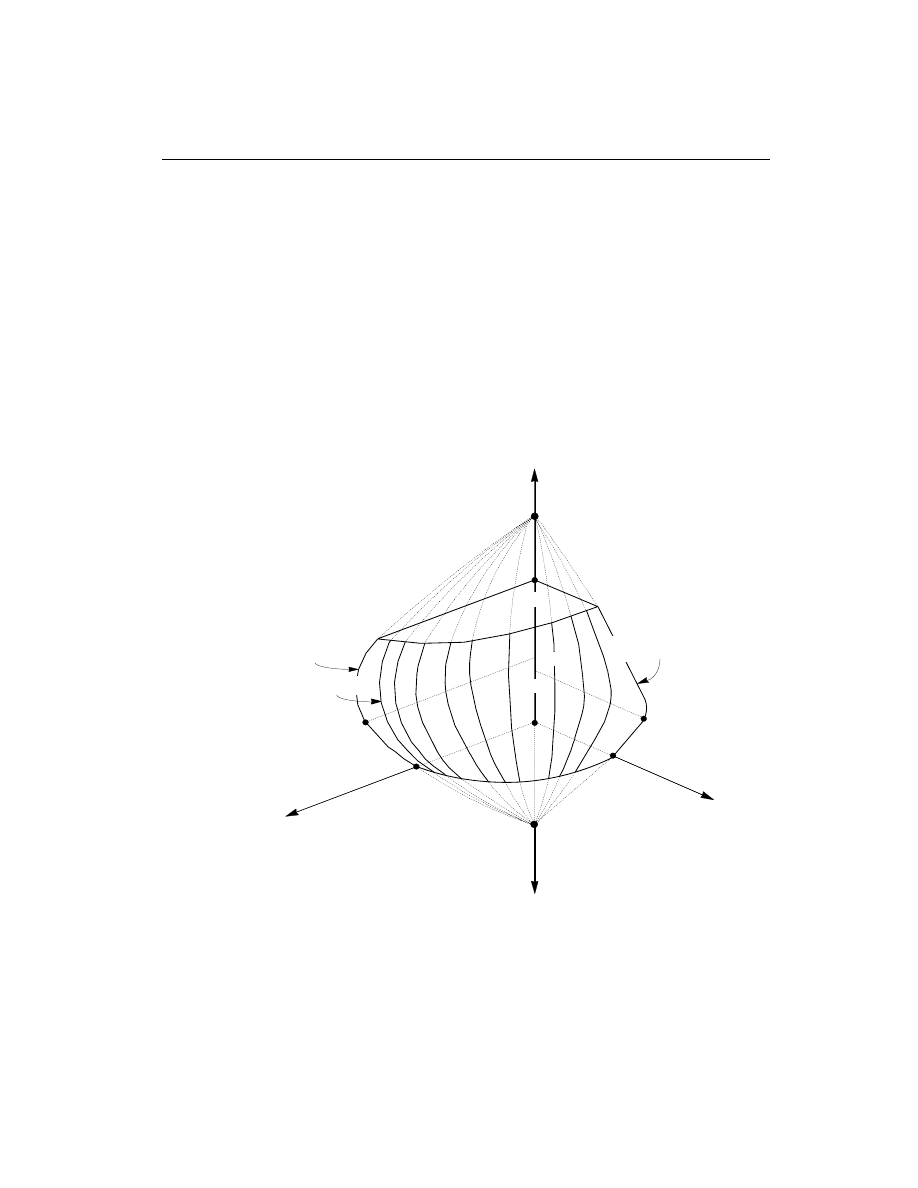
• Generate axial force-biaxial moment interaction surfaces for all of the different
concrete section types of the model. A typical interaction surface is shown in
Figure II-1.
Design of Columns
9
Chapter II Design Algorithms
M
x
M
y
Axial tension
Curve #1
Axial compression
M
by
Curve #NRCV
P
bx
P
max
M
bx
Curve #2
1
2
3
P
by
-P
0
+P
0
Figure II-1
A Typical Column Interaction Surface
• Check the capacity of each column for the factored axial force and bending mo-
ments obtained from each loading combination at each end of the column. This
step is also used to calculate the required reinforcement (if none was specified)
that will produce a capacity ratio of 1.0.
• Design the column shear reinforcement.
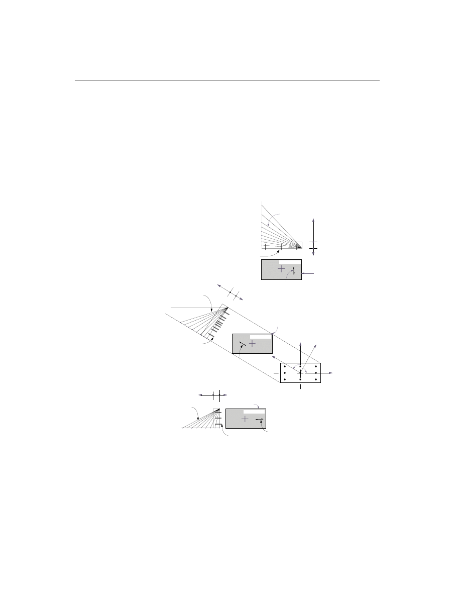
The generation of the interaction surface is based on the assumed strain and stress
distributions and some other simplifying assumptions. These stress and strain dis-
tributions and the assumptions vary from code to code. A typical assumed strain
distribution is described in Figure II-2.
10
Design of Columns
SAP2000 Concrete Design Manual
DIRECTION 1
DIRECTION
2
3
2
1
a
a
DIRECTION
3
−ε
−ε
−ε
+ε
+ε
+ε
Neutral Axis
Direction
Neutral Axis
Direction
Neutral Axis
Direction
ε
c
ε
c
ε
c
ε
c
ε
c
ε
c
0
0
0
Reinforcement
Bars
Reinforcement
Bars
Reinforcement
Bars
Varying Linear
Strain Plane
Varying Linear
Strain Plane
Varying Linear
Strain Plane
Figure II-2
Idealized Strain Distribution for Generation of Interaction Surfaces
Here maximum compression strain is limited to
e
c
. For most of the design codes,
this assumed distribution remains valid. However, the value of
e
c
varies from code
to code. For example,
e
c
= 0.003 for ACI, AASHTO and New Zealand codes, and
e
c
= 0.0035for Canadian, British and European codes. The details of the generation
of interaction surfaces differ from code to code. These are described in the chapters
specific to the code.
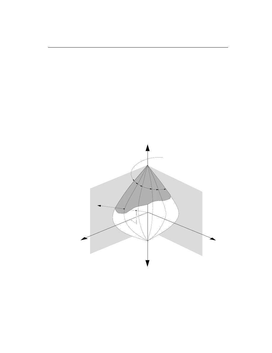
The capacity check is based on whether the design load points lie inside the interac-
tion volume in a force space, as shown in Figure II-3. If the point lies inside the vol-
ume, the column capacity is adequate, and vice versa.
The shear reinforcement design procedure for columns is very similar to that for
beams, except that the effect of the axial force on the concrete shear capacity needs
to be considered.
Design of Columns
11
Chapter II Design Algorithms
Axial Compression
Axial Tension
M
X
M
Y
M
y
M
x
P
o
L
C
Lines Defining
Failure Surface
Figure II-3
Geometric Representation of Column Capacity Ratio

P- Effects
The SAP2000 design algorithms require that the analysis results include the P-
D ef-
fects. The P-
D effects are considered differently for “braced” or “nonsway” and
“unbraced” or “sway” components of moments in columns or frames. For the
braced moments in columns, the effect of P-
D is limited to “individual member sta-
bility”. For unbraced components, “lateral drift effects” should be considered in ad-
dition to individual member stability effect. In SAP2000, it is assumed that
“braced” or “nonsway” moments are contributed from the “dead” or “live” loads.
Whereas, “unbraced” or “sway” moments are contributed from all other types of
loads.
For the individual member stability effects, the moments are magnified with mo-
ment magnification factors as in the ACI, AASHTO, Canadian, and New Zealand
codes or with additional moments as in the British and European codes.
For lateral drift effects, SAP2000 assumes that the P-
D analysis is performed and
that the amplification is already included in the results. The moments and forces ob-
tained from P-
D analysis are further amplified for individual column stability effect
if required by the governing code as in the ACI, Canadian, and New Zealand codes.
The users of SAP2000 should be aware that the default analysis option in SAP2000
is turned OFF for P-
D effect. The user can turn the P-D analysis ON and set the
maximum number of iterations for the analysis. The default number of iteration for
P-
D analysis is 1. For further reference, the user is referred to SAP2000 Analysis
Reference manual.
The user is also cautioned that SAP2000 currently considers P-
D effects due to axial
loads in frame members only. Forces in other types of elements do not contribute to
this effect. If significant forces are present in other type of elements, for example,
huge axial loads in shear walls which are modeled as shell elements, then the addi-
tional forces computed for P-
D will not be accurate.
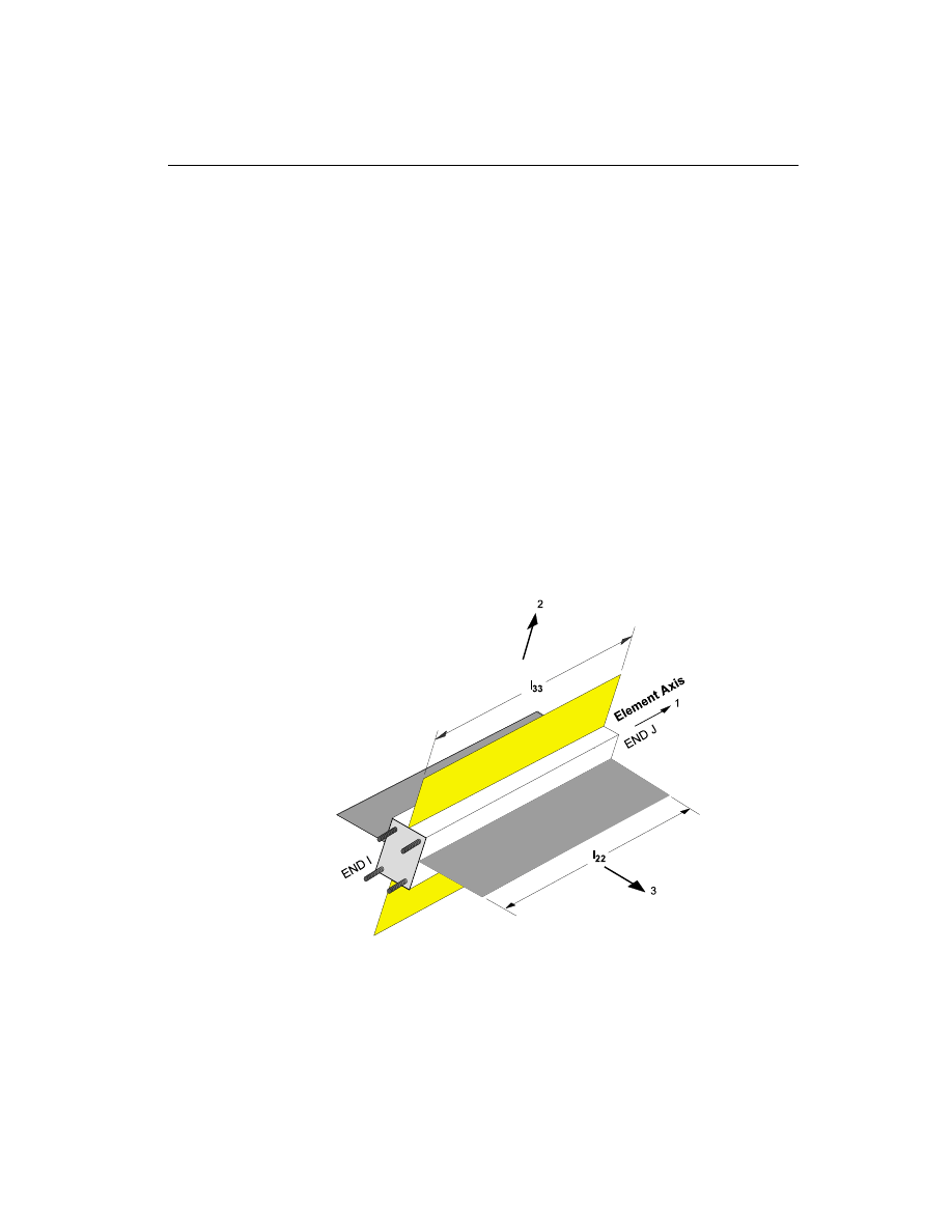
Element Unsupported Lengths
To account for column slenderness effects the column unsupported lengths are re-
quired. The two unsupported lengths are l
33
and l
22
. These are the lengths between
support points of the element in the corresponding directions. The length l
33
corre-
sponds to instability about the 3-3 axis (major axis), and l
22
corresponds to instabil-
ity about the 2-2 axis (minor axis).
12
P-
D Effects
SAP2000 Concrete Design Manual
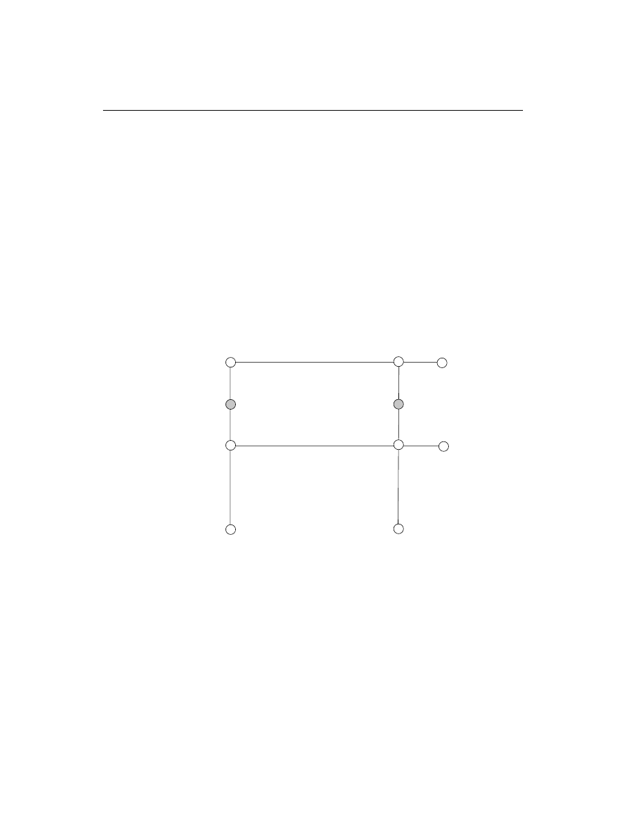
Normally, the unsupported element length is equal to the length of the element, i.e.,
the distance between END-I and END-J of the element. See Figure II-4. The pro-
gram, however, allows users to assign several elements to be treated as a single
member for design. This can be done differently for major and minor bending.
Therefore, extraneous joints, as shown in Figure II-5, that affect the unsupported
length of an element are automatically taken into consideration.
In determining the values for l
22
and l
33
of the elements, the program recognizes
various aspects of the structure that have an effect on these lengths, such as member
connectivity, diaphragm constraints and support points. The program automati-
cally locates the element support points and evaluates the corresponding unsup-
ported element length.
Therefore, the unsupported length of a column may actually be evaluated as being
greater than the corresponding element length. If the beam frames into only one di-
rection of the column, the beam is assumed to give lateral support only in that direc-
tion.
The user has options to specify the unsupported lengths of the elements on an ele-
ment-by-element basis.
Element Unsupported Lengths
13
Chapter II Design Algorithms
Figure II-4
Axes of Bending and Unsupported Length
Special Considerations for Seismic Loads
The ACI code imposes a special ductility requirement for frames in seismic regions
by specifying frames either as Ordinary, Intermediate, or Special moment resisting
frames. The Special moment resisting frame can provide the required ductility and
energy dissipation in the nonlinear range of cyclic deformation. The AASHTO
code requires that the concrete frame must be in either Zone 1, Zone 2, Zone 3, or
Zone 4, where Zone 4 is designated as the zone of severe earthquake. The Canadian
code requires that the concrete frame must be designed as either an Ordinary,
Nominal, or Ductile moment resisting frame. The New Zealand code also requires
that the concrete frame must be designed as either an Ordinary, Elastically respond-
ing, frames with Limited ductility, or Ductile moment resisting frame.
Unlike the ACI, AASHTO, Canadian, and New Zealand codes, the current imple-
mentation of the British code and the Eurocode 2 in SAP2000 does not account for
any special requirements for seismic design.
Choice of Input Units
English as well as SI and MKS metric units can be used for input. But the codes are
based on a specific system of units. All equations and descriptions presented in the
subsequent chapters correspond to that specific system of units unless otherwise
14
Special Considerations for Seismic Loads
SAP2000 Concrete Design Manual
Figure II-5
Unsupported Lengths and Interior Nodes

noted. For example, the ACI code is published in inch-pound-second units. By de-
fault, all equations and descriptions presented in the chapter “Design for ACI
318-99” correspond to inch-pound-second units. However, any system of units can
be used to define and design the structure in SAP2000.
Choice of Input Units
15
Chapter II Design Algorithms


C h a p t e r III
Design for ACI 318-99
This chapter describes in detail the various aspects of the concrete design procedure
that is used by SAP2000 when the user selects the ACI 318-99 Design Code (ACI
1999). Various notations used in this chapter are listed in Table III-1.
The design is based on user-specified loading combinations. But the program pro-
vides a set of default load combinations that should satisfy requirements for the de-
sign of most building type structures.
SAP2000 provides options to design or check Ordinary, Intermediate (moderate
seismic risk areas), and Special (high seismic risk areas) moment resisting frames
as required for seismic design provisions. The details of the design criteria used for
the different framing systems are described in the following sections.
English as well as SI and MKS metric units can be used for input. But the code is
based on Inch-Pound-Second units. For simplicity, all equations and descriptions
presented in this chapter correspond to Inch-Pound-Second units unless otherwise
noted.
Design Load Combinations
The design load combinations are the various combinations of the prescribed load
cases for which the structure needs to be checked. For the ACI 318-99 code, if a
Design Load Combinations
17

18
Design Load Combinations
SAP2000 Concrete Design Manual
A
cv
Area of concrete used to determine shear stress, sq-in
A
g
Gross area of concrete, sq-in
A
s
Area of tension reinforcement, sq-in
A
s
¢
Area of compression reinforcement, sq-in
A
s required
(
)
Area of steel required for tension reinforcement, sq-in
A
st
Total area of column longitudinal reinforcement, sq-in
A
v
Area of shear reinforcement, sq-in
a
Depth of compression block, in
a
b
Depth of compression block at balanced condition, in
b
Width of member, in
b
f
Effective width of flange (T-Beam section), in
b
w
Width of web (T-Beam section), in
C
m
Coefficient, dependent upon column curvature, used to calculate mo-
ment magnification factor
c
Depth to neutral axis, in
c
b
Depth to neutral axis at balanced conditions, in
d
Distance from compression face to tension reinforcement, in
d
¢
Concrete cover to center of reinforcing, in
d
s
Thickness of slab (T-Beam section), in
E
c
Modulus of elasticity of concrete, psi
E
s
Modulus of elasticity of reinforcement, assumed as 29,000,000 psi
f
c
¢
Specified compressive strength of concrete, psi
f
y
Specified yield strength of flexural reinforcement, psi
f
ys
Specified yield strength of shear reinforcement, psi
h
Dimension of column, in
I
g
Moment of inertia of gross concrete section about centroidal axis,
neglecting reinforcement, in
4
I
se
Moment of inertia of reinforcement about centroidal axis of
member cross section, in
4
k
Effective length factor
L
Clear unsupported length, in
Table III-1
List of Symbols Used in the ACI code

Design Load Combinations
19
Chapter III Design for ACI 318-99
M
1
Smaller factored end moment in a column, lb-in
M
2
Larger factored end moment in a column, lb-in
M
c
Factored moment to be used in design, lb-in
M
ns
Nonsway component of factored end moment, lb-in
M
s
Sway component of factored end moment, lb-in
M
u
Factored moment at section, lb-in
M
ux
Factored moment at section about X-axis, lb-in
M
uy
Factored moment at section about Y-axis, lb-in
P
b
Axial load capacity at balanced strain conditions, lb
P
c
Critical buckling strength of column, lb
P
max
Maximum axial load strength allowed, lb
P
0
Axial load capacity at zero eccentricity, lb
P
u
Factored axial load at section, lb
r
Radius of gyration of column section, in
V
c
Shear resisted by concrete, lb
V
E
Shear force caused by earthquake loads, lb
V
D
L
+
Shear force from span loading, lb
V
u
Factored shear force at a section, lb
V
p
Shear force computed from probable moment capacity, lb
a
Reinforcing steel overstrength factor
b
1
Factor for obtaining depth of compression block in concrete
b
d
Absolute value of ratio of maximum factored axial dead load to maxi-
mum factored axial total load
d
s
Moment magnification factor for sway moments
d
ns
Moment magnification factor for nonsway moments
e
c
Strain in concrete
e
s
Strain in reinforcing steel
j
Strength reduction factor
Table III-1
List of Symbols Used in the ACI code (continued)

structure is subjected to dead load (DL) and live load (LL) only, the stress check
may need only one load combination, namely 1.4 DL + 1.7 LL (ACI 9.2.1). How-
ever, in addition to the dead and live loads, if the structure is subjected to wind
(WL) and earthquake (EL) loads, and considering that wind and earthquake forces
are reversible, then the following load combinations have to be considered (ACI
9.2).
1.4 DL
1.4 DL + 1.7 LL
(ACI 9.2.1)
0.9 DL
± 1.3 WL
0.75 (1.4 DL + 1.7 LL
± 1.7 WL)
(ACI 9.2.2)
0.9 DL
± 1.3 * 1.1 EL
0.75 (1.4 DL + 1.7 LL
± 1.7 * 1.1 EL)
(ACI 9.2.3)
These are also the default design load combinations in SAP2000 whenever the ACI
318-99 code is used.
Live load reduction factors can be applied to the member forces of the live load
condition on an element-by-element basis to reduce the contribution of the live load
to the factored loading.
Strength Reduction Factors
The strength reduction factors,
j, are applied on the nominal strength to obtain the
design strength provided by a member. The
j factors for flexure, axial force, shear,
and torsion are as follows:
j = 0.90 for flexure,
(ACI 9.3.2.1)
j = 0.90 for axial tension,
(ACI 9.3.2.2)
j = 0.90 for axial tension and flexure,
(ACI 9.3.2.2)
j = 0.75 for axial compression, and axial compression
and flexure (spirally reinforced column),
(ACI 9.3.2.2)
j = 0.70 for axial compression, and axial compression
and flexure (tied column), and
(ACI 9.3.2.2)
j = 0.85 for shear and torsion.
(ACI 9.3.2.3)
20
Strength Reduction Factors
SAP2000 Concrete Design Manual

Column Design
The user may define the geometry of the reinforcing bar configuration of each con-
crete column section. If the area of reinforcing is provided by the user, the program
checks the column capacity. However, if the area of reinforcing is not provided by
the user, the program calculates the amount of reinforcing required for the column.
The design procedure for the reinforced concrete columns of the structure involves
the following steps:
• Generate axial force/biaxial moment interaction surfaces for all of the different
concrete section types of the model. A typical biaxial interaction surface is
shown in Figure II-1. When the steel is undefined, the program generates the
interaction surfaces for the range of allowable reinforcement
1 to 8 percent
for Ordinary and Intermediate moment resisting frames (ACI 10.9.1) and 1 to 6
percent for Special moment resisting frames (ACI 21.4.3.1).
• Calculate the capacity ratio or the required reinforcing area for the factored ax-
ial force and biaxial (or uniaxial) bending moments obtained from each loading
combination at each station of the column. The target capacity ratio is taken as
one when calculating the required reinforcing area.
• Design the column shear reinforcement.
The following three subsections describe in detail the algorithms associated with
the above-mentioned steps.
Generation of Biaxial Interaction Surfaces
The column capacity interaction volume is numerically described by a series of dis-
crete points that are generated on the three-dimensional interaction failure surface.
In addition to axial compression and biaxial bending, the formulation allows for ax-
ial tension and biaxial bending considerations. A typical interaction diagram is
shown in Figure II-1.
The coordinates of these points are determined by rotating a plane of linear strain in
three dimensions on the section of the column. See Figure II-2. The linear strain
diagram limits the maximum concrete strain,
e
c
, at the extremity of the section
to 0.003 (ACI 10.2.3).
The formulation is based consistently upon the general principles of ultimate
strength design (ACI 10.3), and allows for any doubly symmetric rectangular,
square, or circular column section.
Column Design
21
Chapter III Design for ACI 318-99
The stress in the steel is given by the product of the steel strain and the steel modu-
lus of elasticity,
e
s
s
E , and is limited to the yield stress of the steel, f
y
(ACI 10.2.4).
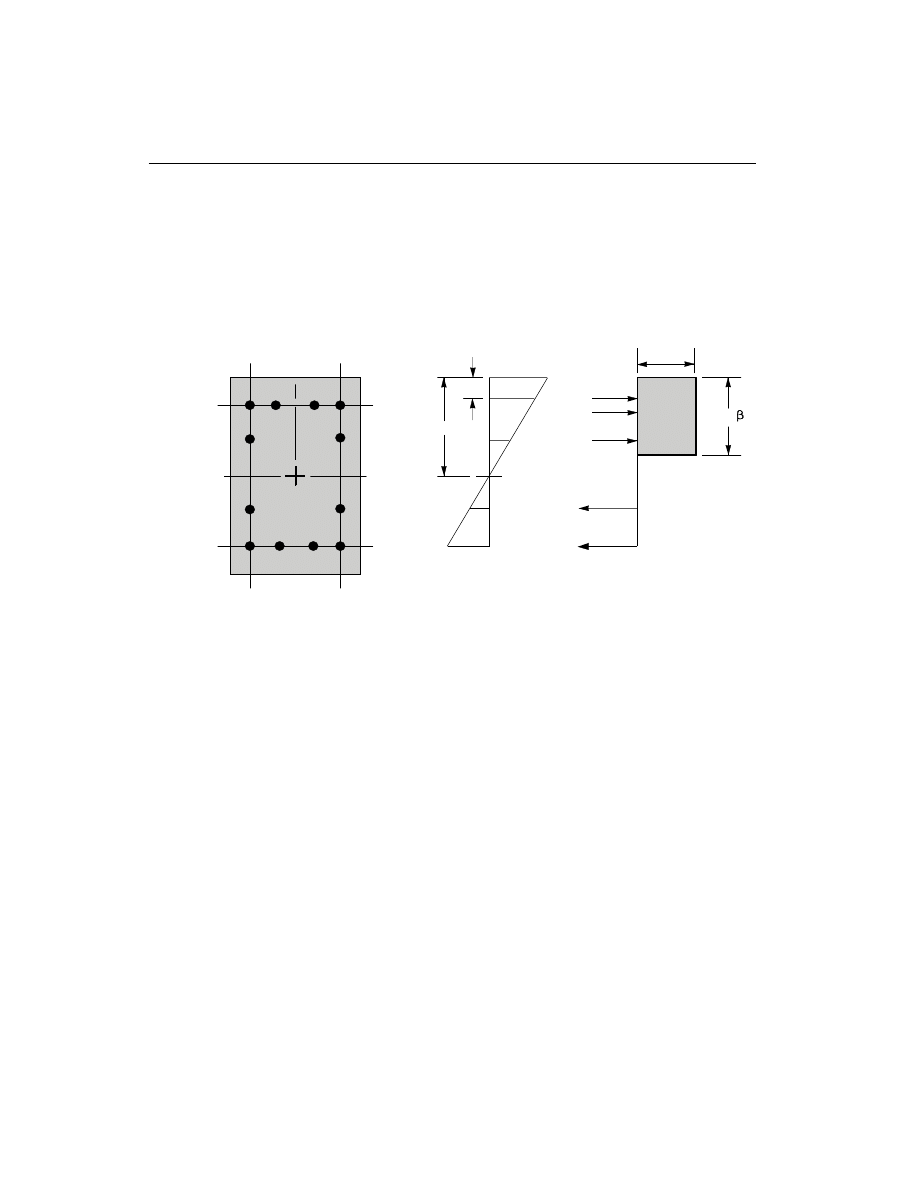
The area associated with each reinforcing bar is assumed to be placed at the actual
location of the center of the bar and the algorithm does not assume any further sim-
plifications in the manner in which the area of steel is distributed over the cross sec-
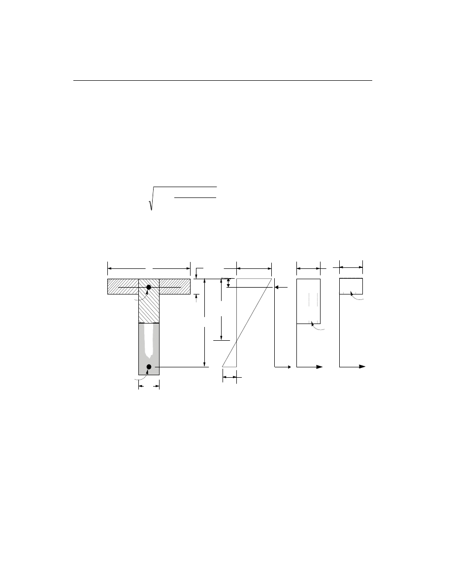
tion of the column, such as an equivalent steel tube or cylinder. See Figure III-1.
The concrete compression stress block is assumed to be rectangular, with a stress
value of 0.85 f
c
¢
(ACI 10.2.7.1). See Figure III-1. The interaction algorithm pro-
vides correction to account for the concrete area that is displaced by the reinforce-
ment in the compression zone.
The effects of the strength reduction factor,
j, are included in the generation of the
interaction surfaces. The maximum compressive axial load is limited to
jP
n(max)
,
where
j
j
P
=
f
A - A
+ f
A
c
g
st
y
st
n(max)
0.85
[ 0.85
(
)
]
¢
spiral column, (ACI 10.3.5.1)
j
j
P
=
f
A - A
f
A
c
g
st
y
st
n(max)
0.80
[ 0.85
(
) +
]
¢
tied column,
(ACI 10.3.5.2)
j = 0.70 for tied columns, and
j = 0.75 for spirally reinforced columns.
22
Column Design
SAP2000 Concrete Design Manual
c
d'
C
a =
c
1
2
s
C
1
s
C
0.85 f'
c
ε
c
= 0.003
ε
s
4
ε
s
3
ε
s
2
ε
s
1
T
s
4
T
s
3
(i) Concrete Section
(ii) Strain Diagram
(iii) Stress Diagram
Figure III-1
Idealization of Stress and Strain Distribution in a Column Section

The value of
j used in the interaction diagram varies from j
min
to 0.9 based on the
axial load. For low values of axial load,
j is increased linearly from j
min
to 0.9 as
the axial load decreases from the smaller of P
b
or 0.1 f A
c
g
¢
to zero, where P
b
is the
axial force at the balanced condition. In cases involving axial tension,
j is always
0.9 (ACI 9.3.2.2).
Check Column Capacity
The column capacity is checked for each loading combination at each check station
of each column. In checking a particular column for a particular loading combina-
tion at a particular station, the following steps are involved:
• Determine the factored moments and forces from the analysis load cases and
the specified load combination factors to give P M
M
u
ux
uy
,
,and
.
• Determine the moment magnification factors for the column moments.
• Apply the moment magnification factors to the factored moments. Determine
whether the point, defined by the resulting axial load and biaxial moment set,
lies within the interaction volume.
The factored moments and corresponding magnification factors depend on the
identification of the individual column as either “sway” or “non-sway”.
The following three sections describe in detail the algorithms associated with the
above-mentioned steps.
Determine Factored Moments and Forces
The factored loads for a particular load combination are obtained by applying the
corresponding load factors to all the load cases, giving P M
M
u
ux
uy
,
,and
. The fac-
tored moments are further increased for non-sway columns, if required, to obtain
minimum eccentricities of (0.6 0.03
+
h) inches, where h is the dimension of the
column in the corresponding direction (ACI 10.12.3.2).
Determine Moment Magnification Factors
The moment magnification factors are calculated separately for sway (overall sta-
bility effect),
d
s
and for non-sway (individual column stability effect),
d
ns
. Also the
moment magnification factors in the major and minor directions are in general dif-
ferent.
The program assumes that a P-
D analysis has been performed in SAP2000 and,
therefore, moment magnification factors for moments causing sidesway are taken
Column Design
23
Chapter III Design for ACI 318-99

as unity (ACI 10.10.2). For the P-
D analysis the load should correspond to a load
combination of 0.75 (1.4 dead load + 1.7 live load)/
j, where j is the understrength
factor for stability which is taken as 0.75 (ACI 10.12.3). See also White and Hajjar
(1991).
The moment obtained from analysis is separated into two components: the sway
(
)
M
s
and the non-sway (M
ns
) components. The non-sway components which are
identified by “ns” subscripts are predominantly caused by gravity load. The sway
components are identified by the “s” subscripts. The sway moments are predomi-
nantly caused by lateral loads, and are related to the cause of side sway.
For individual columns or column-members in a floor, the magnified moments
about two axes at any station of a column can be obtained as
M
M
M
ns
s
s
=
+ d
.
(ACI 10.13.3)
The factor
d
s
is the moment magnification factor for moments causing side sway.
The moment magnification factors for sway moments,
d
s
, is taken as 1 because the
component moments M
s
and M
ns
are obtained from a “second order elastic (P-
D)
analysis” (ACI R10.13).
The computed moments are further amplified for individual column stability effect
(ACI 10.13.5) by the nonsway moment magnification factor,
d
ns
, as follows:
M
M
c
ns
= d
2
, where
(ACI 10.12.3)
M
c
is the factored moment to be used in design, and
M
2
is the larger factored and amplified end moment.
The non-sway moment magnification factor,
d
ns
, associated with the major or mi-
nor direction of the column is given by (ACI 10.12.3)
d
ns
m
u
c
C
P
P
=
0.75
1.0
1
-
³
, where
P =
EI
kl
c
u
p
2
2
(
)
,
k is conservatively taken as 1, however SAP2000 allows the user to override
this value, and
EI is associated with a particular column direction given by:
24
Column Design
SAP2000 Concrete Design Manual

EI =
E I
+
c
g
d
0.4
1
b
,
b
d
=
maximum factored axial dead load
maximum factored axial total load
, and
C
=
+
M
M
m
a
b
0.6
0.4
0.4
³
.
(ACI 10.12.3.1)
M
a
and M
b
are the moments at the ends of the column, and M
b
is numerically
larger than M
a
. M
M
a
b
is positive for single curvature bending and negative
for double curvature bending. The above expression of C
m
is valid if there is no
transverse load applied between the supports. If transverse load is present on
the span, or the length is overwritten, or for any other case, C
m
=1. C
m
can be
overwritten by the user on an element by element basis.
The magnification factor,
d
ns
, must be a positive number and greater than one.
Therefore P
u
must be less than 0.75P
c
. If P
u
is found to be greater than or equal to
0.75P
c
, a failure condition is declared.
The above calculations use the unsupported length of the column. The two unsup-
ported lengths are l
22
and l
33
corresponding to instability in the minor and major di-
rections of the element, respectively. See Figure II-4. These are the lengths between
the support points of the element in the corresponding directions.
If the program assumptions are not satisfactory for a particular member, the user
can explicitly specify values of
d
d
s
ns
and
.
Determine Capacity Ratio
As a measure of the stress condition of the column, a capacity ratio is calculated.
The capacity ratio is basically a factor that gives an indication of the stress condi-
tion of the column with respect to the capacity of the column.
Before entering the interaction diagram to check the column capacity, the moment
magnification factors are applied to the factored loads to obtain P M
M
u
ux
uy
,
, and
.
The point (P M
M
u
ux
uy
,
,
) is then placed in the interaction space shown as point L in
Figure II-3. If the point lies within the interaction volume, the column capacity is
adequate; however, if the point lies outside the interaction volume, the column is
overstressed.
This capacity ratio is achieved by plotting the point L and determining the location
of point C. The point C is defined as the point where the line OL (if extended out-
Column Design
25
Chapter III Design for ACI 318-99

wards) will intersect the failure surface. This point is determined by three-
dimensional linear interpolation between the points that define the failure surface.
See Figure II-3. The capacity ratio, CR, is given by the ratio
OL
OC
.
• If OL = OC (or CR=1) the point lies on the interaction surface and the column is
stressed to capacity.
• If OL < OC (or CR<1) the point lies within the interaction volume and the col-
umn capacity is adequate.
• If OL > OC (or CR>1) the point lies outside the interaction volume and the col-
umn is overstressed.
The maximum of all the values of CR calculated from each load combination is re-
ported for each check station of the column along with the controlling
P M
M
u
ux
uy
,
, and
set and associated load combination number.
If the reinforcing area is not defined, SAP2000 computes the reinforcement that
will give an interaction ratio of unity.
Design Column Shear Reinforcement
The shear reinforcement is designed for each loading combination in the major and
minor directions of the column. In designing the shear reinforcing for a particular
column for a particular loading combination due to shear forces in a particular di-
rection, the following steps are involved:
• Determine the factored forces acting on the section, P
u
and V
u
. Note that P
u
is
needed for the calculation of V
c
.
• Determine the shear force, V
c
, that can be resisted by concrete alone.
• Calculate the reinforcement steel required to carry the balance.
For Special and Intermediate moment resisting frames (ductile frames), the shear
design of the columns is also based upon the probable and nominal moment capaci-
ties of the members, respectively, in addition to the factored moments. Effects of
the axial forces on the column moment capacities are included in the formulation.
The following three sections describe in detail the algorithms associated with the
above-mentioned steps.
26
Column Design
SAP2000 Concrete Design Manual

Determine Section Forces
• In the design of the column shear reinforcement of an Ordinary moment re-
sisting concrete frame, the forces for a particular load combination, namely,
the column axial force, P
u
, and the column shear force,V
u
, in a particular direc-
tion are obtained by factoring the SAP2000 analysis load cases with the corre-
sponding load combination factors.
• In the shear design of Special moment resisting frames (seismic design) the
following are checked in addition to the requirement for the Ordinary moment
resisting frames. In the design of Special moment resisting concrete frames, the
design shear force in a column, V
u
, in a particular direction is also calculated
from the probable moment capacities of the column associated with the fac-
tored axial force acting on the column.
For each load combination, the factored axial load, P
u
, is calculated. Then, the
positive and negative moment capacities, M
u
+
and M
u
-
, of the column in a par-
ticular direction under the influence of the axial force P
u
is calculated using the
uniaxial interaction diagram in the corresponding direction. The design shear
force, V
u
, is then given by (ACI 21.4.5.1)
V
V + V
u
p
D+ L
=
(ACI 21.4.5.1)
where, V
p
is the shear force obtained by applying the calculated probable ulti-
mate moment capacities at the two ends of the column acting in two opposite
directions. Therefore, V
p
is the maximum of V
P
1
and V
P
2
, where
V
=
M
+ M
L
P
I
-
J
+
1
, and
V
=
M
+ M
L
P
I
+
J
-
2
, where
M
I
+
, M
I
-
=
Positive and negative moment capacities at end I of
the column using a steel yield stress value of
af
y
and no
j factors (j =1.0),
M
J
+
, M
J
-
=
Positive and negative moment capacities at end J of
the column using a steel yield stress value of
af
y
and no
j factors (j =1.0),
and
L
=
Clear span of column.
Column Design
27
Chapter III Design for ACI 318-99

For Special moment resisting frames
a is taken as 1.25 (ACI R21.4.5.1). V
D
L
+
is the contribution of shear force from the in-span distribution of gravity loads.
For most of the columns, it is zero.
• For Intermediate moment resisting frames, the shear capacity of the column
is also checked for the design nominal shear based on the nominal moment ca-
pacities at the ends and the factored gravity loads, in addition to the check re-
quired for Ordinary moment resisting frames. The design shear force is taken to
be the minimum of that based on the nominal (
j =1.0) moment capacity and
factored shear force. The procedure for calculating nominal moment capacity
is the same as that for computing the probable moment capacity for special mo-
ment resisting frames, except that
a is taken equal to 1 rather than 1.25 (ACI
R21.10). The factored shear forces are based on the specified load factors ex-
cept the earthquake load factors are doubled (ACI 21.10.3).
Determine Concrete Shear Capacity
Given the design force set P
u
and V
u
, the shear force carried by the concrete, V
c
, is
calculated as follows:
• If the column is subjected to axial compression, i.e. P
u
is positive,
V =
f
+
P
A
A
c
c
u
g
cv
2
1
2000
¢
æ
è
ç
ç
ö
ø
÷
÷
,
(ACI 11.3.1.2)
where,
f
c
¢
£ 100 psi, and
(ACI 11.1.2)
V
f
+
P
A
A
c
c
u
g
cv
£
æ
è
ç
ç
ö
ø
÷
÷
¢
3.5
1
500
.
(ACI 11.3.2.2)
The term
P
A
u
g
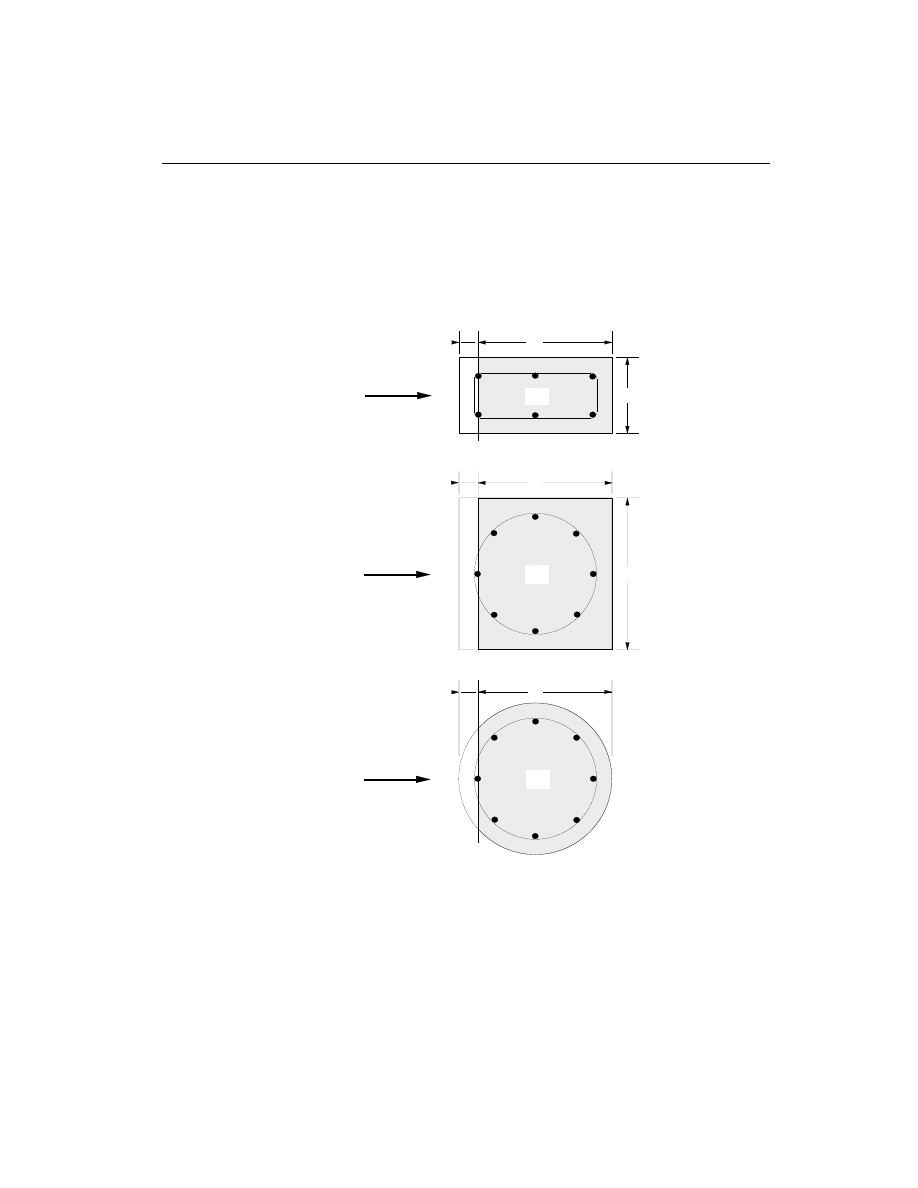
must have psi units. A
cv
is the effective shear area which is shown
shaded in Figure III-2.
• If the column is subjected to axial tension, P
u
is negative,
V =
f
+
P
A
A
c
c
u
g
cv
2
1
500
0
¢
æ
è
ç
ç
ö
ø
÷
÷
³
(ACI 11.3.2.3)
28
Column Design
SAP2000 Concrete Design Manual
• For Special moment resisting concrete frame design, V
c
is set to zero if the
factored axial compressive force, P
u
, including the earthquake effect is small
(
)
P
f A /
u
c
g
<
¢
20
and if the shear force contribution from earthquake, V
E
, is
more than half of the total factored maximum shear force over the length of the
member V
u
(V
V
E
u
³ 0.5 ) (ACI 21.4.5.2).
Column Design
29
Chapter III Design for ACI 318-99
SQUARE WITH CIRCULAR REBAR
DIRECTION
OF SHEAR
FORCE
DIRECTION
OF SHEAR
FORCE
DIRECTION
OF SHEAR
FORCE
d
b
d'
RECTANGULAR
Acv
d'
d
b
Acv
d'
CIRCULAR
d
Acv
Figure III-2
Shear Stress Area, A
cv

Determine Required Shear Reinforcement
Given V
u
and V
c
, the required shear reinforcement in the form of stirrups or ties
within a spacing, s, is given by
A =
V /
V
s
f
d
v
u
c
ys
(
)
j -
,
(ACI 11.5.6.2)
(
/
)
V
V
f A
u
c
c
cv
j -
£
¢
8
(ACI 11.5.6.9)
Otherwise redimensioning of the concrete section is required. Here
j, the strength
reduction factor, is 0.85 (ACI 9.3.2.3). The maximum of all the calculated A
v
val-
ues obtained from each load combination are reported for the major and minor di-
rections of the column along with the controlling shear force and associated load
combination label.
The column shear reinforcement requirements reported by the program are based
purely upon shear strength consideration. Any minimum stirrup requirements to
satisfy spacing considerations or transverse reinforcement volumetric considera-
tions must be investigated independently of the program by the user.
Beam Design
In the design of concrete beams, SAP2000 calculates and reports the required areas
of steel for flexure and shear based upon the beam moments, shears, load combina-
tion factors, and other criteria described below. The reinforcement requirements
are calculated at a user defined number of check/design stations along the beam
span.
All the beams are only designed for major direction flexure and shear. Effects
due to any axial forces, minor direction bending, and torsion that may exist in
the beams must be investigated independently by the user.
The beam design procedure involves the following steps:
• Design beam flexural reinforcement
• Design beam shear reinforcement
30
Beam Design
SAP2000 Concrete Design Manual

Design Beam Flexural Reinforcement
The beam top and bottom flexural steel is designed at check/design stations along
the beam span. In designing the flexural reinforcement for the major moment for a
particular beam for a particular section, the following steps are involved:
• Determine the maximum factored moments
• Determine the reinforcing steel
Determine Factored Moments
In the design of flexural reinforcement of Special, Intermediate, or Ordinary mo-
ment resisting concrete frame beams, the factored moments for each load combina-
tion at a particular beam section are obtained by factoring the corresponding mo-
ments for different load cases with the corresponding load factors.
The beam section is then designed for the maximum positive M
u
+
and maximum
negative M
u
-
factored moments obtained from all of the load combinations
.
Negative beam moments produce top steel. In such cases the beam is always de-
signed as a rectangular section. Positive beam moments produce bottom steel. In
such cases the beam may be designed as a Rectangular- or a T-beam.
Determine Required Flexural Reinforcement
In the flexural reinforcement design process, the program calculates both the ten-
sion and compression reinforcement. Compression reinforcement is added when
the applied design moment exceeds the maximum moment capacity of a singly re-
inforced section. The user has the option of avoiding the compression reinforce-
ment by increasing the effective depth, the width, or the grade of concrete.
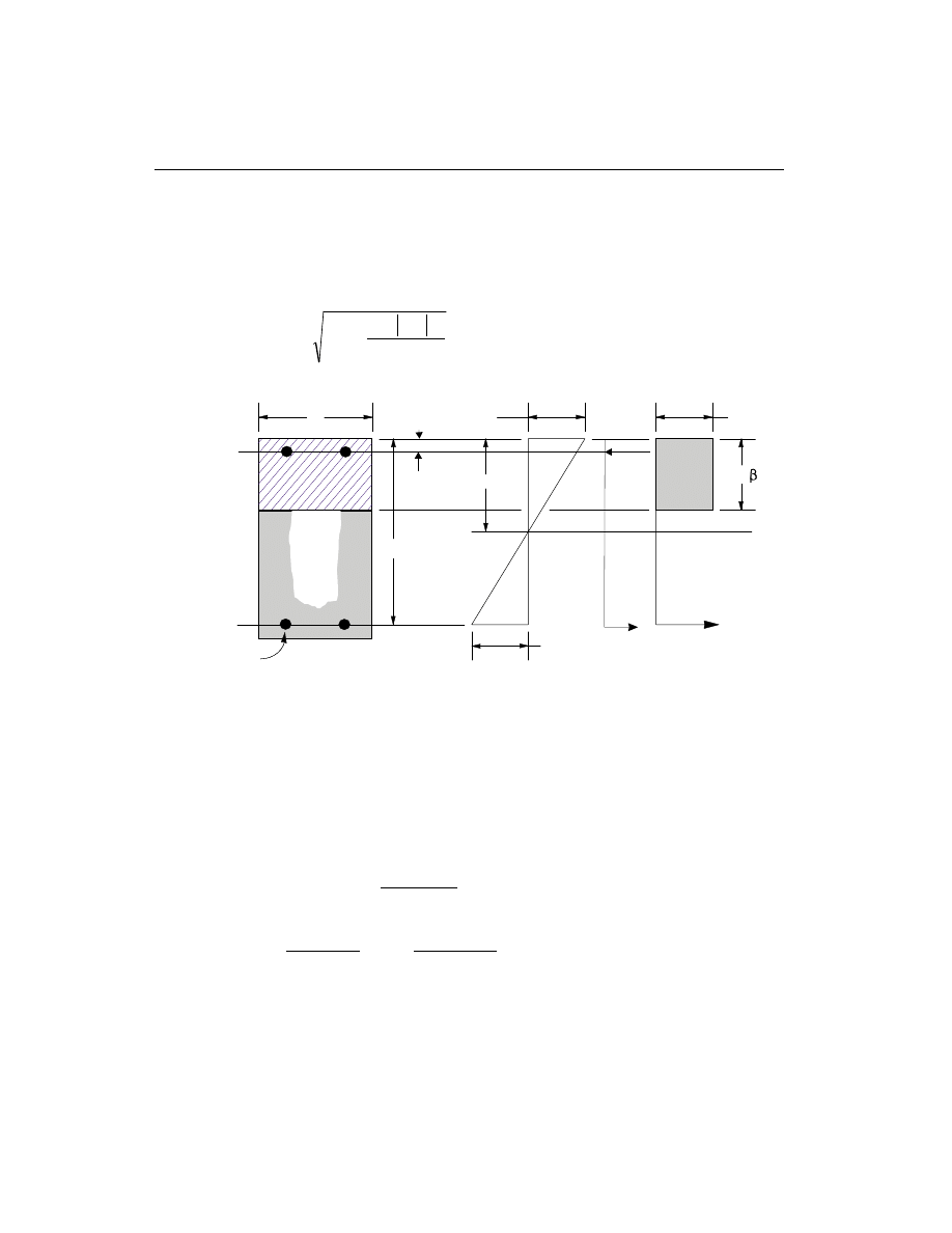
The design procedure is based on the simplified rectangular stress block as shown
in Figure III-3 (ACI 10.2). Furthermore it is assumed that the compression carried
by concrete is less than 0.75 times that which can be carried at the balanced condi-
tion (ACI 10.3.3). When the applied moment exceeds the moment capacity at this
designed balanced condition, the area of compression reinforcement is calculated
on the assumption that the additional moment will be carried by compression and
additional tension reinforcement.
The design procedure used by SAP2000, for both rectangular and flanged sections
(L- and T-beams) is summarized below. It is assumed that the design ultimate axial
force does not exceed 0.1f A
c
g
¢
(ACI 10.3.3), hence all the beams are designed for
major direction flexure and shear only.
Beam Design
31
Chapter III Design for ACI 318-99
Design for Rectangular Beam
In designing for a factored negative or positive moment, M
u
, (i.e. designing top or
bottom steel) the depth of the compression block is given by a (see Figure III-3),
where,
a
d
d
M
f
b
u
c
= -
-
¢
2
2
0.85
j
,
where, the value of
j is 0.90 (ACI 9.3.2.1) in the above and the following equa-
tions. Also
b
1
and c
b
are calculated as follows:
b
1
= 0.85
0.05
-
-
æ
è
çç
ö
ø
÷÷
¢
f
c
4000
1000
,
0.65
0.85
£
£
b
1
,
(ACI 10.2.7.3)
c
E
E + f
d
=
+ f
d
b
c
s
c
s
y
y
= e
e
87 000
87 000
.
(ACI 10.2.3, 10.2.4)
The maximum allowed depth of the compression block is given by
a
c
b
max
= 0.75b
1
.
(ACI 10.2.7.1)
32
Beam Design
SAP2000 Concrete Design Manual
0.85f'
c
c
b
d
A
s
(i) BEAM
SECTION
(ii) STRAIN
DIAGRAM
(iii) STRESS
DIAGRAM
a =
c
1
= 0.003
ε
ε
s
A'
s
d'
C
s
T
s
T
c
Figure III-3
Design of Rectangular Beam Section

• If a
a
£
max
, the area of tensile steel reinforcement is then given by
A
M
f
d
a
s
u
y
=
-
æ
è
ç
ö
ø
÷
j
2
.
This steel is to be placed at the bottom if M
u
is positive, or at the top if M
u
is
negative.
• If a
a
>
max
, compression reinforcement is required (ACI 10.3.3) and is calcu-
lated as follows:
– The compressive force developed in concrete alone is given by
C
f ba
c
=
¢
0.85
max
, and
(ACI 10.2.7.1)
the moment resisted by concrete compression and tensile steel is
M
C d
a
uc
=
-
æ
è
ç
ö
ø
÷
max
2
j .
– Therefore the moment resisted by compression steel and tensile steel is
M
M
M
us
u
uc
=
-
.
– So the required compression steel is given by
A
M
f
d
d
s
us
s
¢
¢
=
- ¢
(
)
j
, where
f
E
c
d
c
s
s
¢
=
- ¢
é
ëê
ù
ûú
0.003
.
(ACI 10.2.4)
– The required tensile steel for balancing the compression in concrete is
A
M
f
d
a
s
uc
y
1
2
=
-
é
ëê
ù
ûú
max
j
, and
the tensile steel for balancing the compression in steel is given by
A
M
f
d
d
s
us
y
2
=
- ¢
(
)
j
.
Beam Design
33
Chapter III Design for ACI 318-99
– Therefore, the total tensile reinforcement, A
A
A
s
s
s
=
+
1
2
, and total com-
pression reinforcement is A
s
¢
. A
s
is to be placed at bottom and A
s
¢
is to be
placed at top if M
u
is positive, and vice versa if M
u
is negative.
Design for T-Beam
In designing for a factored negative moment, M
u
, (i.e. designing top steel), the cal-
culation of the steel area is exactly the same as above, i.e., no T-Beam data is to be
used. See Figure III-4. If M
u
> 0 , the depth of the compression block is given by
a
d
d
M
f
b
u
c
f
= -
-
¢
2
2
0.85
j
.
The maximum allowed depth of compression block is given by
a
c
b
max
= 0.75b
1
.
(ACI 10.2.7.1)
• If a
d
s
£ , the subsequent calculations for A
s
are exactly the same as previously
defined for the rectangular section design. However, in this case the width of
the compression flange is taken as the width of the beam for analysis. Whether
compression reinforcement is required depends on whether a
a
>
max
.
34
Beam Design
SAP2000 Concrete Design Manual
c
b
f
d
A
s
(i) BEAM
SECTION
(ii) STRAIN
DIAGRAM
(iii) STRESS
DIAGRAM
= 0.003
ε
ε
s
d
s
0.85f'
c
C
f
T
f
0.85f'
c
C
w
T
w
b
w
A
s
'
C
s
T
s
d'
f
s
'
Figure III-4
Design of a T-Beam Section

• If a
d
s
> , calculation for A
s
is done in two parts. The first part is for balancing
the compressive force from the flange, C
f
, and the second part is for balancing
the compressive force from the web, C
w
, as shown in Figure III-4. C
f
is given
by
C
f
b
b
d
f
c
f
w
s
=
-
¢
0.85
(
)
.
Therefore, A =
C
f
s
f
y
1
and the portion of M
u
that is resisted by the flange is
given by
M
= C
d
d
uf
f
s
-
æ
è
ç
ö
ø
÷
2
j .
Again, the value for
j is 0.90. Therefore, the balance of the moment, M
u
to be
carried by the web is given by
M
= M
M
uw
u
uf
-
.
The web is a rectangular section of dimensions b
w
and d, for which the design
depth of the compression block is recalculated as
a
d
d
M
f
b
uw
c
w
1
2
2
= -
-
¢
0.85
j
.
• If a
a
1
£
max
, the area of tensile steel reinforcement is then given by
A
M
f
d
a
s
uw
y
2
1
2
=
-
æ
è
ç
ö
ø
÷
j
, and
A
A
A
s
s
s
=
+
1
2
.
This steel is to be placed at the bottom of the T-beam.
• If a
a
1
>
max
, compression reinforcement is required (ACI 10.3.3) and is
calculated as follows:
– The compressive force in web concrete alone is given by
C
f ba
c
=
¢
0.85
max
.
(ACI 10.2.7.1)
Beam Design
35
Chapter III Design for ACI 318-99
– Therefore the moment resisted by concrete web and tensile steel is
M
C d
a
uc
=
-
æ
è
ç
ö
ø
÷
max
2
j , and
the moment resisted by compression steel and tensile steel is
M
M
M
us
uw
uc
=
-
.
– Therefore, the compression steel is computed as
A
M
f
d
d
s
us
s
¢
¢
=
- ¢
(
)
j
, where
f
E
c
d
c
s
s
¢
=
- ¢
é
ëê
ù
ûú
0.003
.
(ACI 10.2.4)
– The tensile steel for balancing compression in web concrete is
A
M
f
d
a
s
uc
y
2
2
=
-
æ
è
ç
ö
ø
÷
max
j
, and
the tensile steel for balancing compression in steel is
A
M
f
d
d
s
us
y
3
=
- ¢
(
)
j
.
– The total tensile reinforcement, A
A
A
A
s
s
s
s
=
+
+
1
2
3
, and total com-
pression reinforcement is A
s
¢
. A
s
is to be placed at bottom and A
s
¢
is to be
placed at top.
Minimum Tensile Reinforcement
The minimum flexural tensile steel provided in a rectangular section in an Ordinary
moment resisting frame is given by the minimum of the two following limits:
A
f
f
b d
f
b d
s
c
y
w
y
w
³
ì
í
ï
îï
ü
ý
ï
þï
¢
max
and
3
200
or
(ACI 10.5.1)
A
A
s
s required
³
4
3
(
).
(ACI 10.5.3)
36
Beam Design
SAP2000 Concrete Design Manual

Special Consideration for Seismic Design
For Special moment resisting concrete frames (seismic design), the beam design
satisfies the following additional conditions (see also Table III-2 for comprehen-
sive listing) :
• The minimum longitudinal reinforcement shall be provided at both at the top
and bottom. Any of the top and bottom reinforcement shall not be less than
A
s min
(
)
(ACI 21.3.2.1).
A
f
f
b d
f
b d
c
y
w
y
w
s(min)
³
ì
í
ï
îï
ü
ý
ï
þï
¢
max
and
3
200
or
(ACI 10.5.1)
A
A
s required
s(min)
³
4
3
(
)
.
(ACI 10.5.3)
• The beam flexural steel is limited to a maximum given by
A
b d
s
w
³ 0.025
.
(ACI 21.3.2.1)
• At any end (support) of the beam, the beam positive moment capacity (i.e. as-
sociated with the bottom steel) would not be less than ½ of the beam negative
moment capacity (i.e. associated with the top steel) at that end (ACI 21.3.2.2).
• Neither the negative moment capacity nor the positive moment capacity at any
of the sections within the beam would be less than 1/4 of the maximum of posi-
tive or negative moment capacities of any of the beam end (support) stations
(ACI 21.3.2.2).
For Intermediate moment resisting concrete frames (seismic design), the beam de-
sign would satisfy the following conditions:
• At any support of the beam, the beam positive moment capacity would not be
less than 1/3 of the beam negative moment capacity at that end (ACI 21.10.4.1).
• Neither the negative moment capacity nor the positive moment capacity at any
of the sections within the beam would be less than 1/5 of the maximum of posi-
tive or negative moment capacities of any of the beam end (support) stations
(ACI 21.10.4.1).
Beam Design
37
Chapter III Design for ACI 318-99

Design Beam Shear Reinforcement
The shear reinforcement is designed for each load combination at a user defined
number of stations along the beam span. In designing the shear reinforcement for a
particular beam for a particular loading combination at a particular station due to
the beam major shear, the following steps are involved:
• Determine the factored shear force, V
u
.
• Determine the shear force, V
c
, that can be resisted by the concrete.
• Determine the reinforcement steel required to carry the balance.
For Special and Intermediate moment resisting frames (ductile frames), the shear
design of the beams is also based upon the probable and nominal moment capacities
of the members, respectively, in addition to the factored load design.
The following three sections describe in detail the algorithms associated with the
above-mentioned steps.
Determine Shear Force and Moment
• In the design of the beam shear reinforcement of an Ordinary moment resist-
ing concrete frame, the shear forces and moments for a particular load combi-
nation at a particular beam section are obtained by factoring the associated
shear forces and moments with the corresponding load combination factors.
• In the design of Special moment resisting concrete frames (seismic design),
the shear capacity of the beam is also checked for the probable shear due to the
probable moment capacities at the ends and the factored gravity load. This
check is done in addition to the design check required for Ordinary moment re-
sisting frames. The shear force,V
u
, is calculated from the probable moment ca-
pacities of each end of the beam and the gravity shear forces. The procedure for
calculating the design shear force in a beam from probable moment capacity is
the same as that described for a column in section “Column Design” on page
27. See also Table III-2 for details.
The design shear force V
u
is then given by (ACI 21.3.4.1)
V
V + V
u
p
D+ L
=
(ACI 21.3.4.1)
where, V
p
is the shear force obtained by applying the calculated probable ulti-
mate moment capacities at the two ends of the beams acting in two opposite di-
rections. Therefore, V
p
is the maximum of V
P
1
and V
P
2
, where
38
Beam Design
SAP2000 Concrete Design Manual

V
=
M
+ M
L
P
I
-
J
+
1
, and
V
=
M
+ M
L
P
I
+
J
-
2
, where
M
I
-
=
Moment capacity at end I, with top steel
in tension, using a steel yield stress value
of
af
y
and no
j factors (j =1.0),
M
J
+
=
Moment capacity at end J, with bottom
steel in tension, using a steel yield stress
value of
af
y
and no
j factors (j =1.0),
M
I
+
=
Moment capacity at end I, with bottom
steel in tension, using a steel yield stress
value of
af
y
and no
j factors (j =1.0),
M
J
-
=
Moment capacity at end J, with top steel
in tension, using a steel yield stress value
of
af
y
and no
j factors (j =1.0), and
L
=
Clear span of beam.
For Special moment resisting frames
a is taken as 1.25 (ACI R21.3.4.1). V
D
L
+
is the contribution of shear force from the in-span distribution of gravity loads.
• For Intermediate moment resisting frames, the shear capacity of the beam is
also checked for the design nominal shear based on the nominal moment
capacities at the ends and the factored gravity loads, in addition to the check re-
quired for Ordinary moment resisting frames. The design shear force in beams
is taken to be the minimum of that based on the nominal moment capacity and
factored shear force. The procedure for calculating nominal (
j =1.0) moment
capacity is the same as that for computing the probable moment capacity for
Special moment resisting frames, except that
a is taken equal to 1 rather than
1.25 (ACI R21.10). The factored shear forces are based on the specified load
factors except the earthquake load factors are doubled (ACI 21.10.3). The com-
putation of the design shear force in a beam of an Intermediate moment re-
sisting frame, is also the same as that for columns, which is described earlier
on page 28. See also Table III-2 for details.
Beam Design
39
Chapter III Design for ACI 318-99

Determine Concrete Shear Capacity
The allowable concrete shear capacity is given by
V =
f
b d
c
c
w
2
¢
.
(ACI 11.3.1.1)
For Special moment resisting frame concrete design,V
c
is set to zero if both the fac-
tored axial compressive force including the earthquake effect P
u
is less than
f A /
c
g
¢
20 and the shear force contribution from earthquake V
E
is more than half of
the total maximum shear force over the length of the member V
u
(i.e. V
V
E
u
³ 0.5 )
(ACI 21.3.4.2).
Determine Required Shear Reinforcement
Given V
V
u
c
and
, the required shear reinforcement in area/unit length is calculated
as
A
V /
V
s
f
d
v
u
c
ys
=
-
(
)
j
.
(ACI 11.5.6.2)
The shear force resisted by steel is limited by
V /
V
f bd
u
c
c
j -
£
¢
8
,
(ACI 11.5.6.9)
where,
j, the strength reduction factor, is 0.85 (ACI 9.3.2.3). The maximum of all
the calculated A
v
values, obtained from each load combination, is reported along
with the controlling shear force and associated load combination number.
The beam shear reinforcement requirements displayed by the program are based
purely upon shear strength considerations. Any minimum stirrup requirements to
satisfy spacing and volumetric considerations must be investigated independently
of the program by the user.
40
Beam Design
SAP2000 Concrete Design Manual
Beam Design
41
Chapter III Design for ACI 318-99
Type of
Check/
Design
Ordinary Moment
Resisting Frames
(non-Seismic)
Intermediate Moment
Resisting Frames
(Seismic)
Special Moment
Resisting Frames
(Seismic)
Column
Check
(interaction)
NLD
a
Combinations
NLD
a
Combinations
NLD
a
Combinations
Column
Design
(Interaction)
NLD
a
Combinations
1% <
ρ
< 8%
NLD
a
Combinations
1% <
ρ
< 8%
NLD
a
Combinations
α
= 1.0
1% <
ρ
< 6%
Column
Shears
NLD
a
Combinations
Modified NLD
a
Combinations
(earthquake loads doubled)
Column Capacity
ϕ
= 1.0 and
α
= 1.0
NLD
a
Combinations and
Column shear capacity
ϕ
= 1.0 and
α
= 1.25
Beam
Design
Flexure
NLD
a
Combinations
NLD
a
Combinations
NLD
a
Combinations
r £ 0.025
r ³
¢
3
f
f
c
y
,
r ³
200
f
y
Beam Min.
Moment
Override
Check
No Requirement
M
M
uEND
+
uEND
-
³
1
3
{
}
M
M
M
uSPAN
+
u
+
u
END
³
-
1
5
max
,
{
}
M
M
M
uSPAN
u
+
u
END
-
-
³
1
5
max
,
M
M
uEND
+
uEND
-
³
1
2
{
}
M
M
M
uSPAN
+
u
+
u
END
³
-
1
4
max
,
{
}
M
M
M
uSPAN
-
u
-
u
-
END
³
1
4
max
,
Beam Design
Shear
NLD
a
Combinations
Modified NLD
a
Combinations
(earthquake loads doubled)
Beam Capacity Shear (V
P
)
with
α
= 1.0 and
ϕ
= 1.0
plus V
D L
+
NLD
a
Combinations
Beam Capacity Shear (V
P
)
with
α
= 1.25 and
ϕ
= 1.0
plus V
D L
+
V
c
= 0
a
NLD = Number of specified loading
Table III-2
Design Criteria Table


C h a p t e r IV
Design for AASHTO LRFD 1997
This chapter describes in detail the various aspects of the concrete design procedure
that is used by SAP2000 when the user selects the AASHTO LRFD 1997 Design
Code (AASHTO 1997). Various notations used in this chapter are listed in Table
IV-1.
The design is based on user-specified loading combinations. But the program pro-
vides a set of default load combinations that should help satisfy requirements for
the design of most bridge type structures.
SAP2000 provides options to design or check moment resisting frames of Zones 1
(low seismic activity), 2, 3, and 4 (high seismic activity) as required for seismic de-
sign provisions. The details of the design criteria used for the different seismic
zones are described in the following sections.
English as well as SI and MKS metric units can be used for input. But the code is
based on Inch-Kip-Second units. For simplicity, all equations and descriptions pre-
sented in this chapter correspond to Inch-Kip-Second units unless otherwise
noted.
43

44
SAP2000 Concrete Design Manual
A
cv
Area of concrete used to determine shear stress, sq-in
A
g
Gross area of concrete, sq-in
A
s
Area of tension reinforcement, sq-in
A
s
¢
Area of compression reinforcement, sq-in
A
s required
(
)
Area of steel required for tension reinforcement, sq-in
A
st
Total area of column longitudinal reinforcement, sq-in
A
v
Area of shear reinforcement, sq-in
a
Depth of compression block, in
a
b
Depth of compression block at balanced condition, in
a
max
Maximum allowed depth of compression block, in
b
Width of member, in
b
f
Effective width of flange (T-Beam section), in
b
w
Width of web (T-Beam section), in
C
m
Coefficient, dependent upon column curvature,
used to calculate moment magnification factor
c
Depth to neutral axis, in
c
b
Depth to neutral axis at balanced conditions, in
d
Distance from compression face to tension reinforcement, in
d
¢
Concrete cover to center of reinforcing, in
d
s
Thickness of slab (T-Beam section), in
E
c
Modulus of elasticity of concrete, psi
E
s
Modulus of elasticity of reinforcement, assumed as 29,000 ksi
f
c
¢
Specified compressive strength of concrete, ksi
f
y
Specified yield strength of flexural reinforcement, ksi
f
yh
Specified yield strength of shear reinforcement, ksi
h
Dimension of column, in
I
g
Moment of inertia of gross concrete section about centroidal axis,
neglecting reinforcement, in
4
I
se
Moment of inertia of reinforcement about centroidal axis of
member cross section, in
4
k
Effective length factor
L
Clear unsupported length, in
Table IV-1
List of Symbols Used in the AASHTO code

45
Chapter IV Design for AASHTO LRFD 1997
M
1
Smaller factored end moment in a column, kip-in
M
2
Larger factored end moment in a column, kip-in
M
c
Factored moment to be used in design, kip-in
M
b
Nonsway component of factored end moment, kip-in
M
s
Sway component of factored end moment, kip-in
M
u
Factored moment at section, kip-in
M
ux
Factored moment at section about X-axis, kip-in
M
uy
Factored moment at section about Y-axis, kip-in
P
b
Axial load capacity at balanced strain conditions, kip
P
e
Euler buckling strength of column, kip
P
max
Maximum axial load strength allowed, kip
P
0
Axial load capacity at zero eccentricity, kip
P
u
Factored axial load at section, kip
r
Radius of gyration of column section, in
V
c
Shear resisted by concrete, kip
V
D
L
+
Shear force from span loading, kip
V
u
Factored shear force at a section, kip
V
p
Shear force computed from probable moment capacity, kip
a
Reinforcing steel overstrength factor
b
is a factor indicating the ability of diagonally cracked concrete
to transmit tension
b
1
Factor for obtaining depth of compression block in concrete
b
d
Absolute value of ratio of maximum factored axial dead load to
maximum factored axial total load
q
An angle of inclination of diagonal compressive stresses with the
longitudinal axis of beam or column
d
s
Moment magnification factor for sway moments
d
b
Moment magnification factor for nonsway (braced) moments
e
c
Strain in concrete
e
s
Strain in reinforcing steel
j
Strength reduction factor
Table IV-1
List of Symbols Used in the AASHTO code (continued)

Design Load Combinations
The design load combinations are the various combinations of the prescribed load
cases for which the structure needs to be checked. There are more different types of
loads specified in the code than are considered in the current implementation of the
default load combinations. However, the user has full control of the definition of
loads and load combinations.
There are six types of dead loads: dead load of structural components and nonstruc-
tural attachments (DC), downdrag (DD), dead load of wearing surface and utilities
(DW), horizontal earth pressure load (EH), vertical earth pressure load (EV), earth
surcharge load (ES). Each type of dead load case requires a separate load factor.
There are six types of live loads: vehicular live load (LL), vehicular dynamic load
allowance (IM), vehicular centrifugal force (CE), vehicular braking force (BR), pe-
destrian live load (PL), and live load surcharge (LS). All these load cases require
the same factor and do not need to be treated separately.
If the structure is subjected to structural dead load (DL), live load (LL), wind load
(WL), and earthquake loads (EL), and considering that wind and earthquake forces
are reversible, the following default load combinations have been considered for
Strength and Extreme Event limit states (AASHTO 3.4.1).
1.50 DL
(Strength-IV)
1.25 DL + 1.75 LL
(Strength-I)
0.90 DL
± 1.4 WL
(Strength-III)
1.25 DL
± 1.4 WL
(Strength-III)
1.25 DL + 1.35 LL
± 0.40 WL
(Strength-V)
0.90 DL
± 1.0 EL
(Extreme-I)
1.25 DL + 0.5 LL
± 1.0 EL
(Extreme-I)
These are also the default design load combinations in SAP2000 whenever the
AASHTO LRFD 1997 code is used. The user is expected to define the other load
combinations as necessary.
Live load reduction factors can be applied to the member forces of the live load case
on an element-by-element basis to reduce the contribution of the live load to the
factored loading.
46
Design Load Combinations
SAP2000 Concrete Design Manual

Strength Reduction Factors
The strength reduction factors,
j, are applied on the nominal strength to obtain the
design strength provided by a member. The
jfactors for flexure, axial force, shear,
and torsion are as follows:
j = 0.90 for flexure,
(AASHTO 5.5.4.2.1)
j = 0.90 for axial tension,
(AASHTO 5.5.4.2.1)
j = 0.90 for axial tension and flexure,
(AASHTO 5.5.4.2.1)
j = 0.90 for shear and torsion, and
(AASHTO 5.5.4.2.1)
j = 0.75 for axial compression only, or axial compression and flexure.
(AASHTO 5.5.4.2.1)
j = 0.50 for axial compression only, or axial compression and flexure in
seismic zone 3 and 4.
(AASHTO 5.5.4.2.3, 5.10.11.4.1b)
The value of
j involving axial compression and flexure varies from 0.75 to 0.9
based on the axial load. For low values of axial load,
j is increased linearly from
0.75 to 0.9 as the axial load decreases from 0.1 f A
c
g
¢
to zero (AASHTO 5.5.4.2.1).
For seismic design in Zones 3 and 4, the value of
j involving axial compression
and flexure varies from 0.5 to 0.9 based on the axial load. For low values of axial
load,
j is increased linearly from 0.5 to 0.9 as the axial load decreases from
0.2 f A
c
g
¢
to zero (AASHTO 5.10.11.4.1b). In cases involving axial tension,
j is al-
ways 0.9 (AASHTO 5.5.4.2.1).
Column Design
The user may define the geometry of the reinforcing bar configuration of each con-
crete column section. If the area of reinforcing is provided by the user, the program
checks the column capacity. However, if the area of reinforcing is not provided by
the user, the program calculates the amount of reinforcing required for the column.
The design procedure for the reinforced concrete columns of the structure involves
the following steps:
• Generate axial force/biaxial moment interaction surfaces for all of the different
concrete section types of the model. A typical biaxial interaction surface is
shown in Figure II-1. When the steel is undefined, the program generates the
interaction surfaces for the range of allowable reinforcement ratio (A
A
st
g
)
Strength Reduction Factors
47
Chapter IV Design for AASHTO LRFD 1997

0.135 f
f
c
y
¢
to 0.08 for moment resisting frames (AASHTO 5.7.4.2) and 0.01
to 0.06 for ductile moment resisting frames in seismic Zones 3 and 4
(AASHTO 5.10.11.4.1a).
• Calculate the capacity ratio or the required reinforcing area for the factored ax-
ial force and biaxial (or uniaxial) bending moments obtained from each loading
combination at each station of the column. The target capacity ratio is taken as
1.0 when calculating the required reinforcing area.
• Design the column shear reinforcement.
The following three subsections describe in detail the algorithms associated with
the above-mentioned steps.
Generation of Biaxial Interaction Surfaces
The column capacity interaction volume is numerically described by a series of dis-
crete points that are generated on the three-dimensional interaction failure surface.
In addition to axial compression and biaxial bending, the formulation allows for ax-
ial tension and biaxial bending considerations. A typical interaction diagram is
shown in Figure II-1.
The coordinates of these points are determined by rotating a plane of linear strain in
three dimensions on the section of the column. See Figure II-2. The linear strain
diagram limits the maximum concrete strain,
e
c
, at the extremity of the section
to 0.003 (AASHTO 5.7.2.1).
The formulation is based consistently upon the general principles of ultimate
strength design (AASHTO 5.7), and allows for any doubly symmetric rectangular,
square, or circular column section.
The stress in the steel is given by the product of the steel strain and the steel modu-
lus of elasticity,
e
s
s
E , and is limited to the yield stress of the steel, f
y
(AASHTO
5.7.2.1). The area associated with each reinforcing bar is assumed to be placed at
the actual location of the center of the bar and the algorithm does not assume any
further simplifications in the manner in which the area of steel is distributed over
the cross section of the column, such as an equivalent steel tube or cylinder. See
Figure IV-1.
48
Column Design
SAP2000 Concrete Design Manual
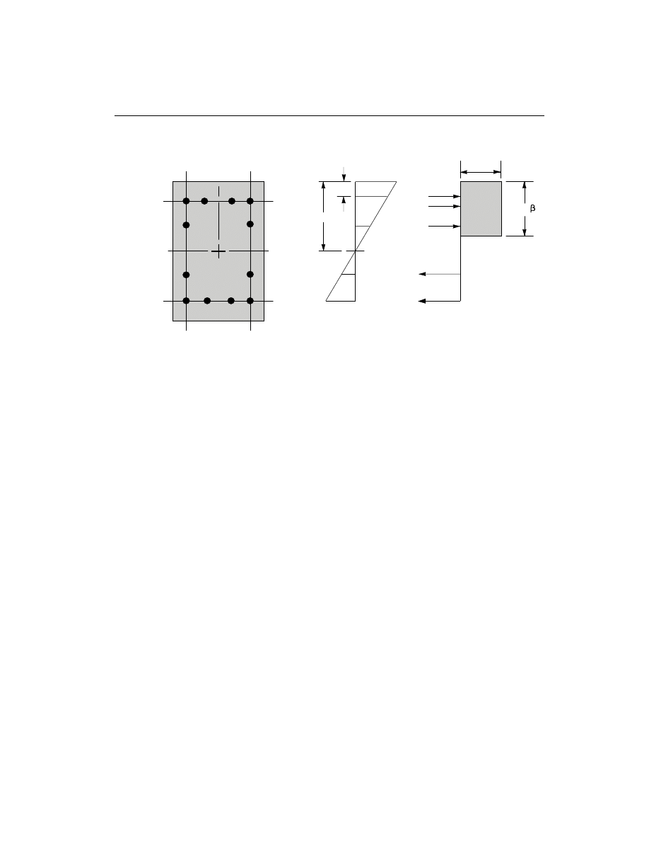
The concrete compression stress block is assumed to be rectangular (AASHTO
5.7.2.1), with a stress value of 0.85 f
c
¢
(AASHTO 5.7.2.2). See Figure IV-1. The
depth of the stress block of
b
1
c, where
b
1
=
-
-
¢
0.85 0.05
4
(
)
f
c
,
(AASHTO 5.7.2.2)
0.65
0.85
£
£
b
1
, and
(AASHTO 5.7.2.2)
The limit of f
c
¢
is taken to be 10 ksi for all seismic regions:
f
c
¢
£ 10 ksi.
(AASHTO 5.1, 5.4.2.1)
The limit of f
y
is taken to be 75 ksi for all frames:
f
y
£ 75 ksi.
(AASHTO 5.4.3.1)
The interaction algorithm provides a correction to account for the concrete area that
is displaced by the reinforcement in the compression zone.
The effects of the strength reduction factor,
j, are included in the generation of the
interaction surfaces. The maximum compressive axial load is limited to P
max
, where
Column Design
49
Chapter IV Design for AASHTO LRFD 1997
c
d'
C
a =
c
1
2
s
C
1
s
C
0.85 f'
c
ε
c
= 0.003
ε
s
4
ε
s
3
ε
s
2
ε
s
1
T
s
4
T
s
3
(i) Concrete Section
(ii) Strain Diagram
(iii) Stress Diagram
Figure IV-1
Idealization of Stress and Strain Distribution in a Column Section

P
=
f
A - A
+ f
A
c
g
st
y
st
max
0.85
[ 0.85
(
)
]
j
¢
spiral column, (AASHTO 5.7.4.4)
P
=
f
A - A
f
A
c
g
st
y
st
max
0.80
[ 0.85
(
) +
]
j
¢
tied column.
(AASHTO 5.7.4.4)
The value of
j involving axial compression and flexure varies from 0.75 to 0.9
based on the axial load. For low values of axial load,
j is increased linearly from
0.75 to 0.9 as the axial load decreases from 0.1 f A
c
g
¢
to zero (AASHTO 5.5.4.2.1).
For seismic design in Zones 3 and 4, the value of
j involving axial compression and
flexure varies from 0.5 to 0.9 based on the axial load. For low values of axial load,
j
is increased linearly from 0.5 to 0.9 as the axial load decreases from 0.2 f A
c
g
¢
to
zero (AASHTO 5.10.11.4.1b). In cases involving axial tension,
j is always 0.9
(AASHTO 5.5.4.2.1).
Check Column Capacity
The column capacity is checked for each loading combination at each check station
of each column. In checking a particular column for a particular loading combina-
tion at a particular station, the following steps are involved:
• Determine the factored moments and forces from the analysis load cases and
the specified load combination factors to give P M
M
u
ux
uy
,
,and
.
• Determine the moment magnification factors for the column moments.
• Apply the moment magnification factors to the factored moments. Determine
whether the point, defined by the resulting axial load and biaxial moment set,
lies within the interaction volume.
The factored moments and corresponding magnification factors depend on the
identification of the individual column as either “braced” or “unbraced”.
The following three sections describe in detail the algorithms associated with the
above-mentioned steps.
Determine Factored Moments and Forces
The factored loads for a particular load combination are obtained by applying the
corresponding load factors to all the load cases, giving P M
M
u
ux
uy
,
,and
. The com-
puted moments are further amplified by using “Moment Magnification Factors” to
allow for stability effects.
50
Column Design
SAP2000 Concrete Design Manual

Determine Moment Magnification Factors
The moment magnification factors are calculated separately for sway (overall sta-
bility effect),
d
s
, and for nonsway or braced (individual column stability effect),
d
ns
. Also the moment magnification factors in the major and minor directions are in
general different.
The program assumes that a P-
D analysis has been performed in SAP2000 and,
therefore, moment magnification factors for moments causing sidesway are taken
as unity (AASHTO 4.5.3). For the P-
D analysis the load should correspond to a load
combination of (1.25 dead load + 1.35 live load) /
j, wherej is the resistance factor
for axial compression which is taken as 0.75 for seismic zones 1 and 2, and as 0.5
for seismic zones 3 and 4 by default (AASHTO 5.5.4.2.1). See also White and
Hajjar (1991).
The moment obtained from analysis is separated into two components: the sway
(
)
M
s
and the nonsway (
)
M
b
components. The non-sway or braced components
which are identified by “b” subscripts are predominantly caused by gravity load.
The sway components are identified by “s” subscripts. The sway moments are pre-
dominantly caused by lateral loads, and are related to the cause of side sway.
For individual columns or column-members in a floor, the magnified moments
about two axes at any station of a column can be obtained as
M
M
M
b
b
s
s
=
+
d
d
.
(AASHTO 4.5.3.2.2b)
The factor
d
s
is the moment magnification factor for moments causing side sway.
This factor is taken as 1 because the component moments M
s
and M
b
are obtained
from a “second order elastic (P-
D) analysis”.
The nonsway moment magnification factor,
d
b
, associated with the major or minor
direction of the column is given by (AASHTO 4.5.3.2.2b),
d
j
b
m
u
e
C
P
P
=
1.0
1
-
³
, where
(AASHTO 4.5.3.2.2b)
P =
EI
kL
e
p
2
2
(
)
,
(AASHTO 4.5.3.2.2b)
k is taken as 1, however SAP2000 allows the user to override this value
(AASHTO 4.6.2.5, 5.7.4.3), and
Column Design
51
Chapter IV Design for AASHTO LRFD 1997
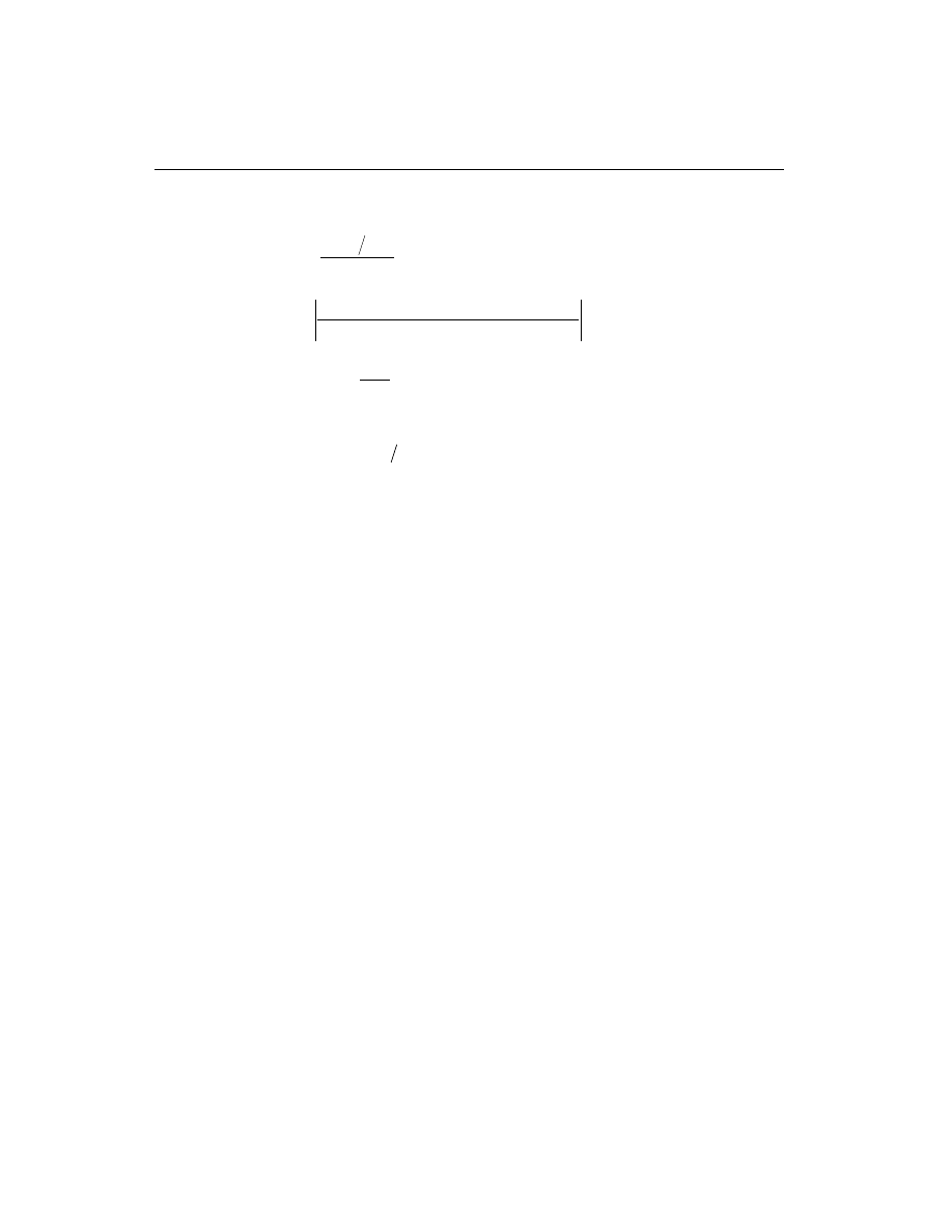
EI is associated with a particular column direction given by:
EI =
E I
+
c
g
d
2.5
1
b
,
(AASHTO 5.7.4.3)
b
d
=
maximum factored dead load moment
maximum factored total load moment
, and
(AASHTO 5.7.4.3)
C
=
+
M
M
m
a
b
0.6
0.4
0.4
³
.
(AASHTO 4.5.3.2.2b)
M
a
and M
b
are the moments at the ends of the column, and M
b
is numerically
larger than M
a
. M
M
a
b
is positive for single curvature bending and negative
for double curvature bending. The above expression of C
m
is valid if there is no
transverse load applied between the supports and the member is braced against
side-sway. If transverse load is present on the span, or the length is overwritten,
or for any other case, C
m
=1. C
m
can be overwritten by the user on an element
by element basis.
The magnification factor,
d
b
, must be a positive number and greater than one.
Therefore P
u
must be less than
jP
e
. If P
u
is found to be greater than or equal to
jP
e
,
a failure condition is declared.
The above calculations use the unsupported lengths of the column. The two unsup-
ported lengths are l
22
and l
33
corresponding to instability in the minor and major di-
rections of the element, respectively. See Figure II-4. These are the lengths between
the support points of the element in the corresponding directions.
If the program assumptions are not satisfactory for a particular member, the user
can explicitly specify values of
d
d
s
b
and
.
Determine Capacity Ratio
As a measure of the stress condition of the column, a capacity ratio is calculated.
The capacity ratio is basically a factor that gives an indication of the stress condi-
tion of the column with respect to the capacity of the column.
Before entering the interaction diagram to check the column capacity, the moment
magnification factors are applied to the factored loads to obtain P M
M
u
ux
uy
,
, and
.
The point (P M
M
u
ux
uy
,
,
) is then placed in the interaction space shown as point L in
Figure II-3. If the point lies within the interaction volume, the column capacity is
adequate; however, if the point lies outside the interaction volume, the column is
overstressed.
52
Column Design
SAP2000 Concrete Design Manual

This capacity ratio is achieved by plotting the point L and determining the location
of point C. Point C is defined as the point where the line OL (if extended outwards)
will intersect the failure surface. This point is determined by three-dimensional lin-
ear interpolation between the points that define the failure surface. See Figure II-3.
The capacity ratio, CR, is given by the ratio
OL
OC
.
• If OL = OC (or CR=1) the point lies on the interaction surface and the column is
stressed to capacity.
• If OL < OC (or CR<1) the point lies within the interaction volume and the col-
umn capacity is adequate.
• If OL > OC (or CR>1) the point lies outside the interaction volume and the col-
umn is overstressed.
The maximum of all the values of CR calculated from each load combination is re-
ported for each check station of the column along with the controlling
P M
M
u
ux
uy
,
, and
set and associated load combination number.
If the reinforcing area is not defined, SAP2000 computes the reinforcement that
will give an interaction ratio of unity.
Design Column Shear Reinforcement
The shear reinforcement is designed for each loading combination in the major and
minor directions of the column. In designing the shear reinforcing for a particular
column for a particular loading combination due to shear forces in a particular di-
rection, the following steps are involved:
• Determine the factored forces acting on the section, M
u
, P
u
and V
u
. Note that
M
u
and P
u
are needed for the calculation of v
c
.
• Determine the shear stress, v
c
, that can be resisted by concrete alone.
• Calculate the reinforcement steel required to carry the balance.
For moment resisting frames in seismic Zones 3 and 4, the shear design of the col-
umns is also based upon the overstrength moment capacities of the members in ad-
dition to the factored moments (AASHTO 3.10.9.4.3). Effects of the axial forces on
the column moment capacities are included in the formulation.
The following three sections describe in detail the algorithms associated with the
above-mentioned steps.
Column Design
53
Chapter IV Design for AASHTO LRFD 1997

Determine Section Forces
• In the design of the column shear reinforcement of moment resisting concrete
frames in seismic Zones 1 and 2, the forces for a particular load combination,
namely, the column axial force, P
u
, and the column shear force, V
u
, in a par-
ticular direction are obtained by factoring the SAP2000 analysis load cases
with the corresponding load combination factors.
• In the shear design of moment resisting frames in seismic Zones 3 and 4
(seismic design), the following are checked in addition to the requirement for
the moment resisting frames in Zones 1 and 2. In the design of moment resist-
ing concrete frames in seismic Zones 3 and 4, the design shear force in a col-
umn, V
u
, in a particular direction is also calculated from the overstrength mo-
ment capacities of the column associated with the factored axial force acting on
the column (AASHTO 3.10.9.4.3).
For each load combination, the factored axial load, P
u
, is calculated. Then, the
positive and negative moment capacities, M
u
+
and M
u
-
, of the column in a par-
ticular direction under the influence of the axial force P
u
is calculated using the
uniaxial interaction diagram in the corresponding direction. The design shear
force, V
u
, is then given by (AASHTO 3.10.9.4.3)
V
V + V
u
p
D+ L
=
(AASHTO 3.10.9.4.3)
where, V
p
is the shear force obtained by applying the calculated overstrength
ultimate moment capacities at the two ends of the column acting in two oppo-
site directions. Therefore, V
p
is the maximum of V
P
1
and V
P
2
, where
V
=
M
+ M
L
P
I
-
J
+
1
, and
V
=
M
+ M
L
P
I
+
J
-
2
, where
M
I
+
, M
I
-
= Positive and negative moment capacities at end I of the col-
umn obtained by multiplying the nominal resistance by 1.3,
M
J
+
, M
J
-
= Positive and negative moment capacities at end J of the col-
umn obtained by multiplying the nominal resistance by 1.3,
and
L
= Clear span of column.
54
Column Design
SAP2000 Concrete Design Manual

V
D
L
+
is the contribution of shear force from the in-span distribution of gravity
loads. For most of the columns, it is zero. See also Table IV-2 for details.
Determine Concrete Shear Capacity
Given the design force set M
u
, P
u
andV
u
, the shear capacity provided by the con-
crete alone, v
c
, is calculated as follows:
• For designing moment resisting concrete frames in any seismic zone, v
c
is
set to:
v =
f
c
c
0.0316
b
¢
,
(AASHTO 5.8.3.3)
where,
b is a factor indicating the ability of diagonally cracked concrete to
transmit tension. It is a function of stress condition and its approximate value is
2.0 (AASHTO 5.8.3.4.1). It is computed from AASHTO Table 5.8.3.4.2-1
through an iterative procedure.
• For designing moment resisting concrete frames in seismic Zones 3 and 4,
v
c
is taken as that given earlier (AASHTO 5.8.3.3) if compressive axial force is
high (
)
P
f A
u
c
g
>
¢
0.1
(AASHTO 5.10.11.4.1c). v
c
is taken as zero if axial
force is tensile. v
c
is linearly interpolated between zero and that given by
AASHTO 5.8.3.3, if the factored axial compressive force, P
u
, including the
earthquake effect is small (
)
P
f A
u
c
g
£
¢
0.1
(AASHTO 5.10.11.4.1c). This pro-
vision is applied to all locations of the column irrespective of whether it is in the
end region or not.
Determine Required Shear Reinforcement
• The average shear stress is computed for a rectangular section as,
v =
V
b d
u
w
.
For other types of sections b d
w
is replaced by A
cv
, the effective shear area
which is shown in Figure IV-2.
• The average shear stress, v, is limited to a maximum limit, v
max
, given by
v
f
c
max
=
¢
0.25
.
(AASHTO 5.8.3.3)
Column Design
55
Chapter IV Design for AASHTO LRFD 1997
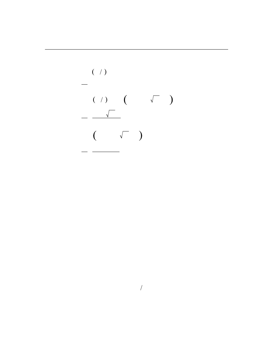
• The shear reinforcement per unit spacing is computed as follows:
If v
v
c
£ j
2 ,
A
s
v
= 0 ,
(AASHTO 5.8.2.4)
else if
j
j
q
v
v
v
f
c
c
c
2
< £
+
¢
0.0316
cot
,
A
s
f b
f
v
c
w
yh
=
¢
0.0316
,
(AASHTO 5.8.2.5)
else if
j
q
j
v
f
v
v
c
c
+
< £
¢
0.0316
cot
max
,
A
s
v
v
b
f
v
c
w
yh
=
-
(
)
cot
j
j
q
,
(AASHTO 5.8.3.3)
else if v
v
>
max
,
a failure condition is declared.
(AASHTO 5.8.3.3)
Here
q is an angle of inclination of diagonal compressive stresses. It is a function of
current stress condition and its approximate value is 45 degree (AASHTO
5.8.3.4.1). It is computed from AASHTO Table 5.8.3.4.2-1 through an iterative
procedure. Here the default value of
j, the strength reduction factor, is 0.90
(AASHTO 5.5.4.2.1).
The limit of f
yh
is taken to be 60 ksi for all frames:
f
yh
£ 60 ksi.
(AASHTO 5.8.2.8)
The limit of f
c
¢
is taken to be 10 ksi for all seismic regions:
f
c
¢
£ 10 ksi.
(AASHTO 5.1, 5.4.2.1)
In calculating the shear reinforcement for seismic moment resisting frames in Zone
3 and 4, a limit was imposed on the f
ys
as
f
f
ys
y
£
.
(AASHTO 5.10.11.4.1d)
The maximum of all the calculated A
s
v
values, obtained from each load combina-
tion, is reported for the major and minor directions of the column along with the
controlling shear force and associated load combination number.
56
Column Design
SAP2000 Concrete Design Manual

For all columns and at any station, the minimum area of transverse circular hoop re-
inforcement is imposed as follows:
A
s
A
A
f
f
h
v
g
c
c
yh
core
³
-
é
ë
ê
ù
û
ú
¢
0.45
1
4
(AASHTO 5.7.4.6)
In potential plastic hinge locations, as described later, of Seismic moment resisting
frames in Zones 2, 3 and 4, the minimum area of circular hoops and transverse stir-
rups is imposed as follows:
A
s
P
f A
f
f
h
v
u
c
g
c
yh
core
³
+
é
ë
ê
ù
û
ú
¢
¢
0.16 0.5
1.25
4
(Hoops)
(AASHTO 5.10.11.4.1d)
A
s
A
A
f
f
h
v
g
c
c
yh
core
³
-
é
ë
ê
ù
û
ú
¢
0.30
1
(Stirrups)
(AASHTO 5.10.11.4.1d)
A
s
P
f A
f
f
h
v
u
c
g
c
yh
core
³
+
é
ë
ê
ù
û
ú
¢
¢
0.12 0.5
1.25
(Stirrups)
(AASHTO 5.10.11.4.1d)
In the above equations, the following limits are imposed:
0.5
1.25
+
é
ë
ê
ù
û
ú ³
¢
P
f A
u
c
g
10
.
(AASHTO 5.10.11.4.1d)
f
f
yh
y
£
(AASHTO 5.10.11.4.1d)
For the definition of the potential plastic hinge, it is assumed in the current version
of the program that any beam and column segment near the joint is a potential plas-
tic hinge. The length of the plastic hinge, L
hinge
, in a column is taken as follows:
L
h b l
hinge
=
¢¢
max
,
,
,
6 18
(AASHTO 5.10.11.4.1c)
The column shear reinforcement requirements reported by the program are based
purely upon the above considerations. Any other minimum stirrup requirements to
satisfy spacing and/or volumetric requirements must be investigated independently
of the program by the user.
Column Design
57
Chapter IV Design for AASHTO LRFD 1997
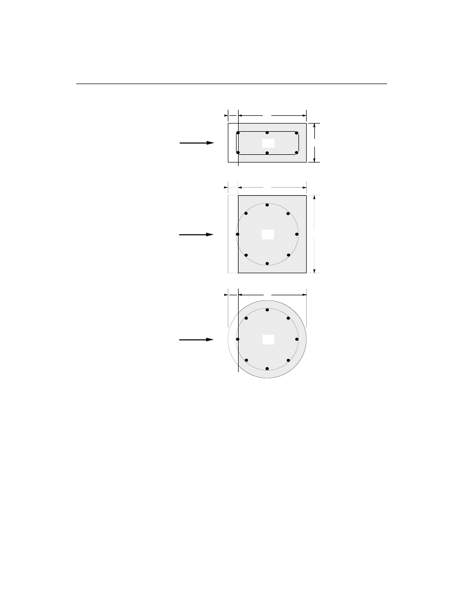
58
Column Design
SAP2000 Concrete Design Manual
SQUARE WITH CIRCULAR REBAR
DIRECTION
OF SHEAR
FORCE
DIRECTION
OF SHEAR
FORCE
DIRECTION
OF SHEAR
FORCE
d
b
d'
RECTANGULAR
Acv
d'
d
b
Acv
d'
CIRCULAR
d
Acv
Figure IV-2
Shear Stress Area, A
cv

Beam Design
In the design of concrete beams, SAP2000 calculates and reports the required areas
of steel for flexure and shear based upon the beam moments, shears, load combina-
tion factors, and other criteria described below. The reinforcement requirements
are calculated at a user defined number of check/design stations along the beam
span.
All the beams are only designed for major direction flexure and shear. Effects
due to any axial forces, minor direction bending, and torsion that may exist in
the beams must be investigated independently by the user.
The beam design procedure involves the following steps:
• Design beam flexural reinforcement
• Design beam shear reinforcement
Design Beam Flexural Reinforcement
The beam top and bottom flexural steel is designed at check/design stations along
the beam span. In designing the flexural reinforcement for the major moment for a
particular beam for a particular section, the following steps are involved:
• Determine the maximum factored moments
• Determine the reinforcing steel
Determine Factored Moments
In the design of flexural reinforcement of moment resisting concrete beams, the
factored moments for each load combination at a particular beam section are ob-
tained by factoring the corresponding moments for different load cases with the
corresponding load factors. The beam section is then designed for the maximum
positive M
u
+
and maximum negative M
u
-
factored moments obtained from all of the
load combinations
.
Negative beam moments produce top steel. In such cases the beam is always de-
signed as a rectangular section. Positive beam moments produce bottom steel. In
such cases the beam may be designed as a Rectangular- or a T-beam.
Beam Design
59
Chapter IV Design for AASHTO LRFD 1997
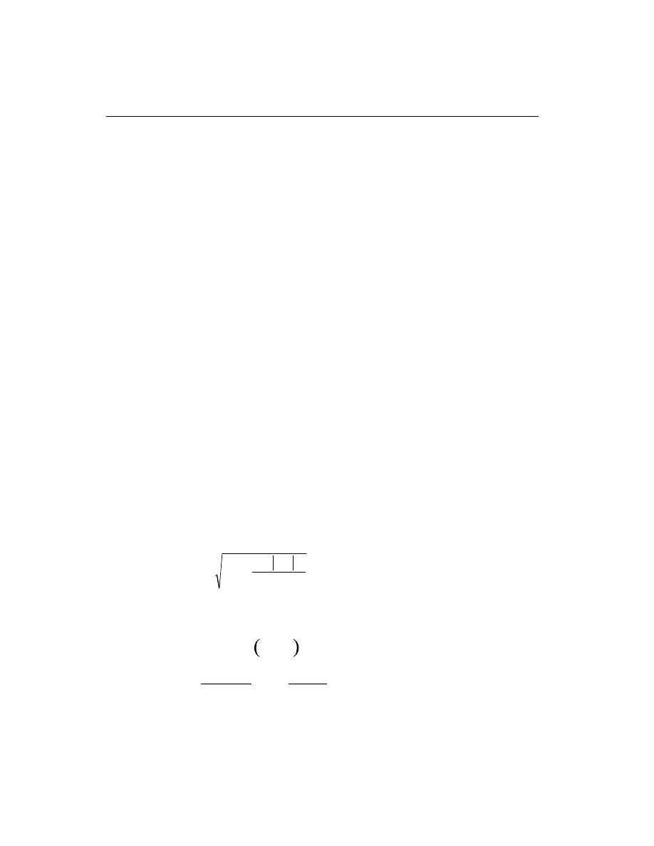
Determine Required Flexural Reinforcement
In the flexural reinforcement design process, the program calculates both the ten-
sion and compression reinforcement. Compression reinforcement is added when
the applied design moment exceeds the maximum moment capacity of a singly re-
inforced section. The user has the option of avoiding the compression reinforce-
ment by increasing the effective depth, the width, or the grade of concrete.
The design procedure is based on the simplified rectangular stress block as shown
in Figure IV-3 (AASHTO 5.7). Furthermore it is assumed that the maximum depth
of compression block is limited to 0.42 d (AASHTO 5.7.3.3.1). When the applied
moment exceeds the moment capacity at this limiting condition, the area of com-
pression reinforcement is calculated on the assumption that the additional moment
will be carried by compression and additional tension reinforcement.
In designing the beam flexural reinforcement, the following limits are imposed on
the steel tensile strength and the concrete compressive strength:
f
c
¢
£ 10 ksi.
(AASHTO 5.1, 5.4.2.1)
f
y
£ 75 ksi.
(AASHTO 5.4.3.1)
The design procedure used by SAP2000, for both rectangular and flanged sections
(L- and T-beams) is summarized below. All the beams are designed for major di-
rection flexure and shear only.
Design for Rectangular Beam
In designing for a factored negative or positive moment, M
u
, (i.e. designing top or
bottom steel) the depth of the compression block is given by a (see Figure IV-3), is
computed as,
a
d
d
M
f
b
u
c
= -
-
¢
2
2
0.85
j
,
(AASHTO 5.7.2.1
where, the value of
j is 0.90 (AASHTO 5.5.4.2.1) in the above and the following
equations. Also
b
1
and c
b
are calculated as follows:
b
1
= 0.85
0.05
-
-
¢
f
c
4 ,
0.65
0.85
£
£
b
1
,
(AASHTO 5.7.2.2)
c =
E
E + f
d
=
+ f
d
b
c
s
c
s
y
y
e
e
87
87
.
(AASHTO 5.7.2.1)
60
Beam Design
SAP2000 Concrete Design Manual
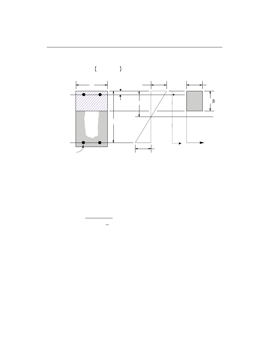
The maximum allowed depth of the compression block is given by
a
c
d
b
max
= min
,
b
1
0.42
.
(AASHTO 5.7.2.2, 5.7.3.3.1)
• If a
a
£
max
(AASHTO 5.7.3.3.1), the area of tensile steel reinforcement is
then given by
A
M
f
d
a
s
u
y
=
-
æ
è
ç
ö
ø
÷
j
2
.
This steel is to be placed at the bottom if M
u
is positive, or at the top if M
u
is
negative.
• If a
a
>
max
(AASHTO 5.7.3.3.1), compression reinforcement is required and is
calculated as follows:
– The compressive force developed in concrete alone is given by
C
f ba
c
=
¢
0.85
max
, and
(AASHTO 5.7.2.2)
Beam Design
61
Chapter IV Design for AASHTO LRFD 1997
0.85f'
c
c
b
d
A
s
(i) BEAM
SECTION
(ii) STRAIN
DIAGRAM
(iii) STRESS
DIAGRAM
a =
c
1
= 0.003
ε
ε
s
A'
s
d'
C
s
T
s
T
c
Figure IV-3
Design of Rectangular Beam Section

the moment resisted by concrete compression and bottom steel is
M
C d
a
uc
=
-
æ
è
ç
ö
ø
÷
max
2
j .
– Therefore the moment resisted by compression steel and tensile steel is
M
M
M
us
u
uc
=
-
.
– So the required compression steel is given by
A
M
f
f
d
d
s
us
s
c
¢
¢
¢
=
-
- ¢
(
)(
)
a
j
1
, where
f
E
c
d
c
s
s
¢
=
- ¢
é
ëê
ù
ûú
0.003
.
(AASHTO 5.7.2.1)
– The required tensile steel for balancing the compression in concrete is
A
M
f
d
a
s
uc
y
1
2
=
-
(
)
max
j
, and
the tensile steel for balancing the compression in steel is given by
A
M
f
d
d
s
us
y
2
=
- ¢
(
)
j
.
– Therefore, the total tensile reinforcement, A
A
A
s
s
s
=
+
1
2
, and total com-
pression reinforcement is A
s
¢
. A
s
is to be placed at bottom and A
s
¢
is to be
placed at top if M
u
is positive, and vice versa.
Design for Flexure of a T-Beam
(i) Flanged Beam Under Negative Moment
In designing for a factored negative moment, M
u
, (i.e. designing top steel), the cal-
culation of the steel area is exactly the same as above, i.e., no T-Beam data is to be
used.
(ii) Flanged Beam Under Positive Moment
If M
u
> 0, the depth of the compression block is given by (see Figure IV-4).
62
Beam Design
SAP2000 Concrete Design Manual
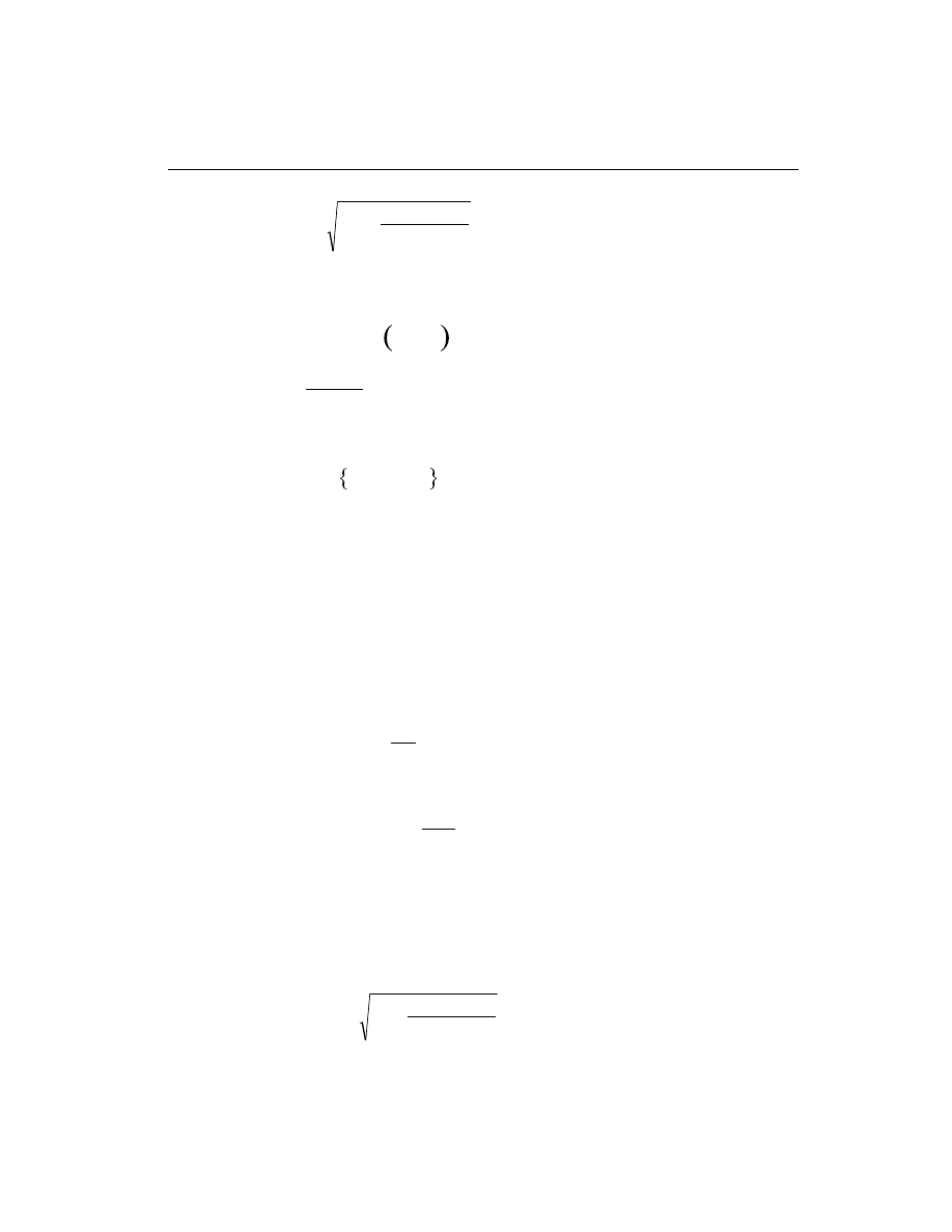
a
d
d
M
f
b
u
c
f
= -
-
¢
2
2
0.85
j
,
(AASHTO 5.7.2.1)
where, the value of
j is 0.90 (AASHTO 5.5.4.2.1) in the above and the following
equations. Also
b
1
and c
b
are calculated as follows:
b
1
= 0.85
0.05
-
-
¢
f
c
4 ,
0.65
0.85
£
£
b
1
,
(AASHTO 5.7.2.1)
c =
+ f
d
b
y
87
87
.
(AASHTO 5.7.2.1)
The maximum allowed depth of the compression block is given by
a
c
d
b
max
= min
,
b
1
0.42
.
(AASHTO 5.7.2.2, 5.7.3.3.1)
• If a
d
s
£ b
1
(AASHTO 5.7.3.2.2), the subsequent calculations for A
s
are ex-
actly the same as previously done for the rectangular section design. However,
in this case b
f
is taken as the width of the beam. Whether compression rein-
forcement is required depends on whether a
a
>
max
.
• If a
d
s
> b
1
(AASHTO 5.7.3.2.2), calculation for A
s
is done in two parts. The
first part is for balancing the compressive force from the flange, C
f
, and the
second part is for balancing the compressive force from the web, C
w
. As shown
in Figure IV-4,
C
f
b
b
d
f
c
f
w
s
=
-
¢
0.85
(
)
b
1
.
(AASHTO 5.7.3.2.2)
Therefore, A =
C
f
s
f
y
1
and the portion of M
u
that is resisted by the flange is
given by
M
= C
d
d
uf
f
s
-
æ
è
ç
ö
ø
÷
b
j
1
2
.
Therefore, the balance of the moment, M
u
to be carried by the web is given by
M
= M
M
uw
u
uf
-
.
The web is a rectangular section of dimensions b
w
and d, for which the design
depth of the compression block is recalculated as
a
d
d
M
f
b
uw
c
w
1
2
2
= -
-
¢
0.85
j
.
Beam Design
63
Chapter IV Design for AASHTO LRFD 1997
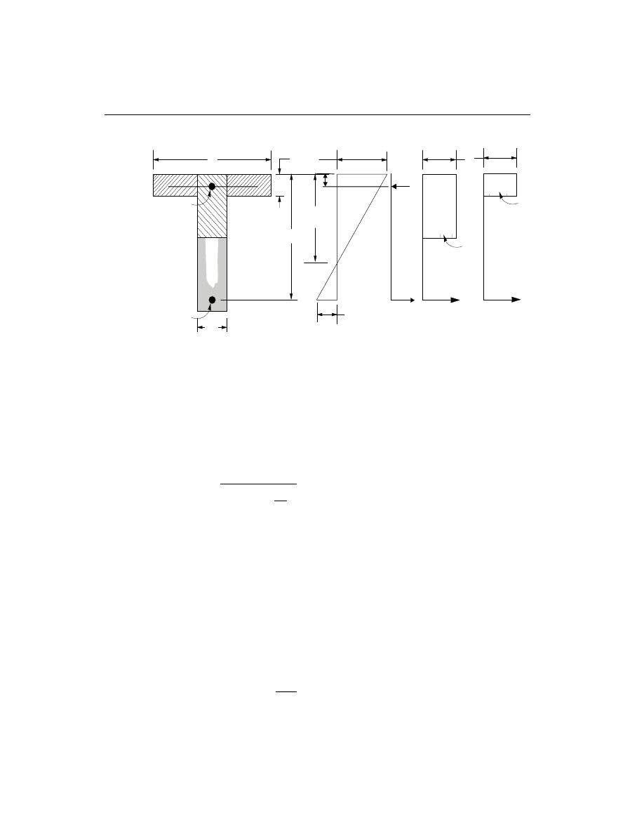
• If a
a
1
£
max
(AASHTO 5.7.3.3.1), the area of tensile steel reinforcement is
then given by
A
M
f
d
a
s
uw
y
2
1
2
=
-
æ
è
ç
ö
ø
÷
j
, and
A
A
A
s
s
s
=
+
1
2
.
This steel is to be placed at the bottom of the T-beam.
• If a
a
1
>
max
(AASHTO 5.7.3.3.1), compression reinforcement is required
and is calculated as follows:
– The compressive force in web concrete alone is given by
C
f ba
c
=
¢
0.85
max
.
(AASHTO 5.7.2.2)
– Therefore the moment resisted by concrete web and tensile steel is
M
C d
a
uc
=
-
æ
è
ç
ö
ø
÷
max
2
j , and
64
Beam Design
SAP2000 Concrete Design Manual
c
b
f
d
A
s
(i) BEAM
SECTION
(ii) STRAIN
DIAGRAM
(iii) STRESS
DIAGRAM
= 0.003
ε
ε
s
d
s
0.85f'
c
C
f
T
f
0.85f'
c
C
w
T
w
b
w
A
s
'
C
s
T
s
d'
f
s
'
Figure IV-4
Design of a T-Beam Section

the moment resisted by compression steel and tensile steel is
M
M
M
us
uw
uc
=
-
.
– Therefore, the compression steel is computed as
A
M
f
f
d
d
s
us
s
c
¢
¢
¢
=
-
- ¢
(
)(
)
a
j
1
, where
f
E
c
d
c
f
s
s
y
¢
=
- ¢
é
ëê
ù
ûú
£
0.003
.
(AASHTO 5.7.2.1)
– The tensile steel for balancing compression in web concrete is
A
M
f
d
a
s
uc
y
2
2
=
-
(
)
max
j
, and
the tensile steel for balancing compression in steel is
A
M
f
d
d
s
us
y
3
=
- ¢
(
)
j
.
– The total tensile reinforcement, A
A
A
A
s
s
s
s
=
+
+
1
2
3
, and total compres-
sion reinforcement is A
s
¢
. A
s
is to be placed at bottom and A
s
¢
is to be
placed at top.
Minimum and Maximum Tensile Reinforcement
The minimum temperature and shrinkage flexural tensile steel provided in a rectan-
gular section is given by:
A
f
b d
b d
s
y
w
w
³
ì
í
î
ü
ý
þ
min
and
0.11
0.0015
or
(AASHTO 5.10.8.2)
The minimum flexural tensile steel provided to prevent premature flexural failure
in a rectangular section is given by:
A
f
f
b d
A
s
c
y
w
s required
³
ì
í
î
ü
ý
þ
¢
min
and
(
)
0.03
4
3
or
(AASHTO 5.7.3.3.2)
An upper limit of 0.04 times the gross web area on both the tension reinforcement
and the compression reinforcement is imposed, upon request, as follows:
Beam Design
65
Chapter IV Design for AASHTO LRFD 1997

A
b d
b d
s
w
£ ìí
î
0.04
Rectangular beam
0.04
T -beam
A
b d
b d
s
w
¢
£ ìí
î
0.04
Rectangular beam
0.04
T -beam
Design Beam Shear Reinforcement
The shear reinforcement is designed for each load combination at a user defined
number of stations along the beam span. In designing the shear reinforcement for a
particular beam for a particular loading combination at a particular station due to
the beam major shear, the following steps are involved:
• Determine the factored forces acting on the section, M
u
and V
u
. Note that M
u
is needed for the calculation of v
c
.
• Determine the shear stress, v
c
, that can be resisted by concrete alone.
• Calculate the reinforcement steel required to carry the balance.
For moment resisting frames in seismic zones 3 and 4, the shear design of the beams
is also based upon the overstrength moment capacities of the members in addition
to the factored moments (AASHTO 3.10.9.4.3).
The following three sections describe in detail the algorithms associated with the
above-mentioned steps.
Determine Shear Force and Moment
• In the design of the beam shear reinforcement of moment resisting concrete
frames in seismic Zones 1 and 2, the shear forces and moments for a particular
load combination at a particular beam section are obtained by factoring the as-
sociated shear forces and moments with the corresponding load combination
factors.
• In the shear design of moment resisting frames in seismic Zones 3 and 4
(seismic design), the following are checked in addition to the requirement for
the moment resisting frames in Zones 1 and 2. In the design of moment resist-
ing concrete frames in seismic Zones 3 and 4, the design shear force in a beam,
V
u
, is also calculated from the overstrength moment capacities of the beam
(AASHTO 3.10.9.4.3). The design shear force V
u
is then given by
V
V + V
u
p
D+ L
=
(AASHTO 3.10.9.4.3)
66
Beam Design
SAP2000 Concrete Design Manual

where V
p
is the shear force obtained by applying the calculated overstrength
ultimate moment capacities at the two ends of the beams acting in two opposite
directions. Therefore, V
p
is the maximum of V
P
1
and V
P
2
, where
V
=
M
+ M
L
P
I
-
J
+
1
, and
V
=
M
+ M
L
P
I
+
J
-
2
, where
M
I
+
, M
I
-
= Positive and negative moment capacities at end I of the beam
obtained by multiplying the nominal resistance by 1.3,
M
J
+
, M
J
-
= Positive and negative moment capacities at end J of the beam
obtained by multiplying the nominal resistance by 1.3,
and
L
= Clear span of beam.
V
D
L
+
is the contribution of shear force from the in-span distribution of gravity
loads. See also Table IV-2 for details.
Determine Concrete Shear Capacity
Given the design force set M
u
and V
u
, the shear capacity provided by the concrete
alone, v
c
, is calculated as follows:
• For designing moment resisting concrete frames in any seismic zone, v
c
is
set to:
v =
f
c
c
0.0316
b
¢
,
(AASHTO 5.8.3.3)
where,
b is a factor indicating the ability of diagonally cracked concrete to
transmit tension. It is a function of stress condition and its approximate value is
2.0 (AASHTO 5.8.3.4.1). It is computed from AASHTO Table 5.8.3.4.2-1
through an iterative procedure.
Determine Required Shear Reinforcement
• The average shear stress is computed for a rectangular section as,
v =
V
b d
u
w
.
Beam Design
67
Chapter IV Design for AASHTO LRFD 1997
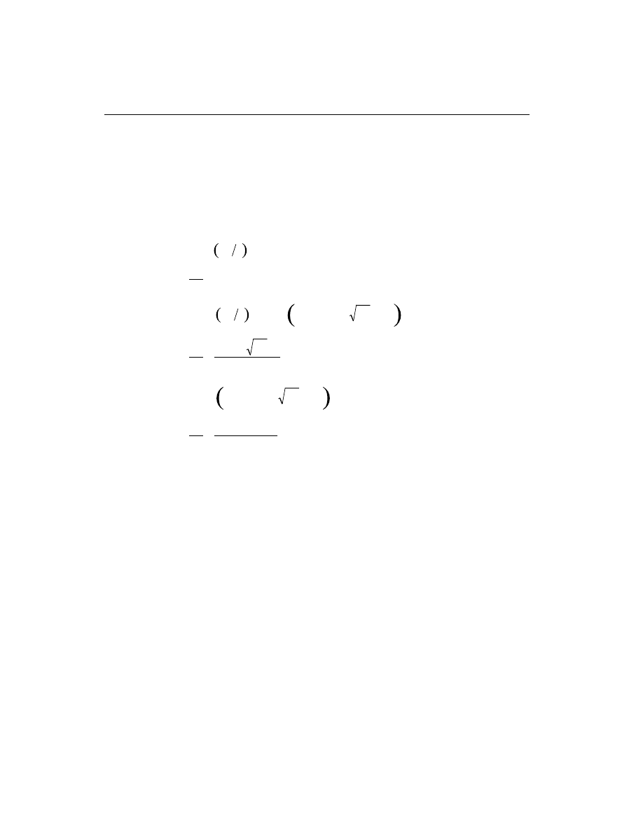
For other types of sections b d
w
is replaced by A
cv
, the effective shear area
which is shown in Figure IV-2.
• The average shear stress, v, is limited to a maximum limit, v
max
, given by
v
f
c
max
=
¢
0.25
.
(AASHTO 5.8.3.3)
• The shear reinforcement per unit spacing is computed as follows:
If v
v
c
£ j
2 ,
A
s
v
= 0 ,
(AASHTO 5.8.2.4)
else if
j
j
q
v
v
v
f
c
c
c
2
< £
+
¢
0.0316
cot
,
A
s
f b
f
v
c
w
yh
=
¢
0.0316
,
(AASHTO 5.8.2.5)
else if
j
q
j
v
f
v
v
c
c
+
< £
¢
0.0316
cot
max
,
A
s
v
v
b
f
v
c
w
yh
=
-
(
)
cot
j
j
q
,
(AASHTO 5.8.3.3)
else if v
v
>
max
,
a failure condition is declared.
(AASHTO 5.8.3.3)
Here
q is an angle of inclination of diagonal compressive stresses. It is a function of
the current stress condition and its approximate value is 45 degrees (AASHTO
5.8.3.4.1). It is computed from AASHTO Table 5.8.3.4.2-1 through an iterative
procedure. Here the default value of
j, the strength reduction factor, is 0.90
(AASHTO 5.5.4.2.1).
The limit of f
yh
is taken to be 60 ksi for all frames:
f
yh
£ 60 ksi.
(AASHTO 5.8.2.8)
The limit of f
c
¢
is taken to be 10 ksi for all seismic regions:
f
c
¢
£ 10 ksi.
(AASHTO 5.1, 5.4.2.1)
68
Beam Design
SAP2000 Concrete Design Manual

The maximum of all the calculated A
s
v
values, obtained from each load combina-
tion, is reported for the major and minor directions of the column along with the
controlling shear force and associated load combination number.
The beam shear reinforcement requirements reported by the program are based
purely upon the above considerations. Any minimum stirrup requirements to sat-
isfy spacing and/or volumetric requirements must be investigated independently of
the program by the user.
Beam Design
69
Chapter IV Design for AASHTO LRFD 1997
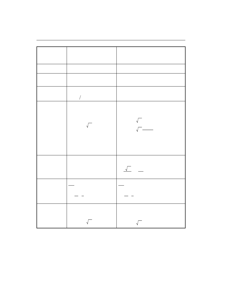
70
Beam Design
SAP2000 Concrete Design Manual
Type of
Check/Design
Moment Resisting Frames
in Zones 1 and 2
(non-Seismic)
Moment Resisting Frames
in Zones 3 and 4
(Seismic)
j In Compression
j =
>
¢
0.75 if
0.10
,
P
f
u
c
j =
>
¢
0.50 if
0.20
,
P
f
u
c
Column Check
(Interaction)
NLD
a
Combinations
NLD
a
Combinations
Column Design
(Interaction)
NLD
a
Combinations
0.135
0.08
f
f
c
y
¢
< <
r
NLD
a
Combinations
0.01
0.06
< <
r
Column Shears
NLD
a
Combinations
v
f
c
c
=
¢
0.0316
b
Minimum volumetric shear
reinforcement in potential plastic
hinge only for Zone 2
NLD
a
Combinations and
Column capacity shear (V
P
) with
overstrength factor 1.3
v
f
c
c
=
¢
0.0316
b
if P
f A
u
c
g
³
¢
0.1
v
f
P
f A
c
c
u
c
g
=
³
¢
¢
0.0316
0.1
b
0 otherwise
Minimum volumetric shear reinforcement in
potential plastic hinge for both Zone 3 and 4
Beam Design
(Flexure)
NLD
a
Combinations
NLD
a
Combinations
r £ 0.025
r ³
¢
3
f
f
c
y
,
r ³
200
f
y
Beam Minimum
Flexural
Reinforcement
0.11
0.0015
0.03
4
3
f
b d
b d
f
f
A
y
w
w
c
f
s required
,
,
,
,
¢
0.11
0.0015
0.03
4
3
f
b d
b d
f
f
A
y
w
w
c
f
s required
,
,
,
,
¢
Beam Design
(Shear)
NLD
a
Combinations
v
f
c
c
=
¢
0.0316
b
NLD
a
Combinations
Beam capacity shear (V
P
) with
overstrength factor 1.3
v
f
c
c
=
¢
0.0316
b
a
NLD = Number of specified loading
Table IV-2
Design Criteria Table

C h a p t e r V
Design for CSA-A23.3-94
This chapter describes in detail the various aspects of the concrete design procedure
that is used by SAP2000 when the user selects the Canadian code, CSA-A23.3-94
(CSA 1994). Various notations used in this chapter are listed in Table V-1.
The design is based on user-specified loading combinations. But the program pro-
vides a set of default load combinations that should satisfy requirements for the de-
sign of most building type structures.
SAP2000 provides options to design or check Ordinary, Nominal (moderate seis-
mic risk areas), and Ductile (high seismic risk areas) moment resisting frames as re-
quired for seismic design. The details of the design criteria used for the different
framing systems are described in the following sections.
English as well as SI and MKS metric units can be used for input. But the code is
based on Newton-Millimeter-Second units. For simplicity, all equations and de-
scriptions presented in this chapter correspond to Newton-Millimeter-Second
units unless otherwise noted.
71

72
SAP2000 Concrete Design Manual
A
cv
Area of concrete used to determine shear stress, sq-mm
A
core
Area of concrete core, sq-mm
A
g
Gross area of concrete, sq-mm
A
s
Area of tension reinforcement, sq-mm
A
s
¢
Area of compression reinforcement, sq-mm
A
s required
(
)
Area of steel required for tension reinforcement, sq-mm
A
st
Total area of column longitudinal reinforcement, sq-mm
A
v
Area of shear reinforcement, sq-mm
a
Depth of compression block, mm
a
b
Depth of compression block at balanced condition, mm
b
Width of member, mm
b
f
Effective width of flange (T-Beam section), mm
b
w
Width of web (T-Beam section), mm
C
m
Coefficient, dependent upon column curvature, used to
calculate moment magnification factor
c
Depth to neutral axis, mm
c
b
Depth to neutral axis at balanced conditions, mm
d
Distance from compression face to tension reinforcement, mm
d
¢
Concrete cover to center of reinforcing, mm
d
s
Thickness of slab (T-Beam section), mm
E
c
Modulus of elasticity of concrete, MPa
E
s
Modulus of elasticity of reinforcement, assumed as 200,000 MPa
f
c
¢
Specified compressive strength of concrete, MPa
f
y
Specified yield strength of flexural reinforcement, MPa
f
yh
Specified yield strength of shear reinforcement, MPa
h
Dimension of beam or column, mm
I
g
Moment of inertia of gross concrete section about centroidal axis,
neglecting reinforcement, mm
4
I
st
Moment of inertia of reinforcement about centroidal axis of
member cross section, mm
4
k
Effective length factor
L
Clear unsupported length, mm
M
1
Smaller factored end moment in a column, N-mm
Table V-1
List of Symbols Used in the Canadian code

73
Chapter V Design for CSA-A23.3-94
M
2
Larger factored end moment in a column, N-mm
M
c
Factored moment to be used in design, N-mm
M
ns
Nonsway component of factored end moment, N-mm
M
s
Sway component of factored end moment, N-mm
M
f
Factored moment at section, N-mm
M
fx
Factored moment at section about X-axis, N-mm
M
fy
Factored moment at section about Y-axis, N-mm
P
b
Axial load capacity at balanced strain conditions, N
P
c
Critical buckling strength of column, N
P
r,max
Maximum axial load strength allowed, N
P
0
Axial load capacity at zero eccentricity, N
P
f
Factored axial load at section, N
V
c
Shear resisted by concrete, N
V
D
L
+
Shear force from span loading, N
V
p
Shear force computed from probable moment capacity, N
V
f
Factored shear force at a section, N
V
s
Shear force at a section resisted by steel, N
a
Reinforcing steel overstrength factor
b
is a factor indicating the ability of diagonally cracked concrete
to transmit tension
q
An angle of inclination of diagonal compressive stresses with the
longitudinal axis of beam or column
b
1
Factor for obtaining depth of compression block in concrete
a
1
Factor for obtaining average compressive stress in concrete block
b
d
Absolute value of the ratio of the maximum factored axial dead load
moment to the maximum factored total load moment
d
b
Moment magnification factor for nonsway moments
d
s
Moment magnification factor for sway moments
e
c
Strain in concrete
e
s
Strain in reinforcing steel
j
c
Strength reduction factor for concrete
j
s
Strength reduction factor for steel
j
m
Strength reduction factor for member
l
Shear strength factor
Table V-1
List of Symbols Used in the Canadian code (continued)

Design Load Combinations
The design load combinations are the various combinations of the prescribed load
cases for which the structure needs to be checked. For this code, if a structure is sub-
jected to dead load (DL), live load (LL), wind (WL), and earthquake (EL) loads,
and considering that wind and earthquake forces are reversible, then the following
load combinations may have to be considered (CSA 8.3):
1.25 DL
1.25 DL + 1.50 LL
(CSA 8.3.2)
1.25 DL
± 1.50 WL
0.85 DL
± 1.50 WL
1.25 DL + 0.7 (1.50 LL
± 1.50 WL)
(CSA 8.3.2)
1.00 DL
± 1.50 EL
1.00 DL + (0.50 LL
± 1.00 EL)
(CSA 8.3.2)
These are also the default design load combinations in SAP2000 whenever the Ca-
nadian Code is used.
In generating the above default loading combinations, the importance factor is
taken as 1. The user should use other appropriate loading combinations if roof live
load is separately treated, other types of loads are present, or pattern live loads are
to be considered.
Live load reduction factors can be applied to the member forces of the live load case
on an element-by-element basis to reduce the contribution of the live load to the
factored loading.
Strength Reduction Factors
The strength reduction factor,
j, is material dependent and is defined as
j
c
= 0.60 for concrete and
(CSA 8.4.2 )
j
s
= 0.85 for steel.
(CSA 8.4.3)
In some special cases, a member resistance factor,
j
m
, is used as an additional re-
duction factor in addition to
j
c
and
j
s
(CSA 8.4.1). In connection with buckling
resistance,
j
m
is taken as 0.75 (CSA 10.15.3).
74
Design Load Combinations
SAP2000 Concrete Design Manual

Column Design
The user may define the geometry of the reinforcing bar configuration of each con-
crete column section. If the area of reinforcing is provided by the user, the program
checks the column capacity. However, if the area of reinforcing is not provided by
the user, the program calculates the amount of reinforcing required for the column.
The design procedure for the reinforced concrete columns of the structure involves
the following steps:
• Generate axial force/biaxial moment interaction surfaces for all of the different
concrete section types of the model. A typical biaxial interaction surface is
shown in Figure II-1. When the steel is undefined, the program generates the
interaction surfaces for the range of allowable reinforcement
1 to 8 percent
for Ordinary and Nominal moment resisting frames (CSA 10.9.1 and CSA
10.9.2) and 1 to 6 percent for Ductile moment resisting frames (CSA 21.4.3.1).
• Calculate the capacity ratio or the required reinforcing area for the factored ax-
ial force and biaxial (or uniaxial) bending moments obtained from each loading
combination at each station of the column. The target capacity ratio is taken as
one when calculating the required reinforcing area.
• Design the column shear reinforcement.
The following three subsections describe in detail the algorithms associated with
the above-mentioned steps.
Generation of Biaxial Interaction Surfaces
The column capacity interaction surface is numerically described by a series of dis-
crete points that are generated in the three-dimensional interaction failure space. In
addition to axial compression and biaxial bending, the formulation allows for axial
tension and biaxial bending considerations. A typical interaction diagram is shown
in Figure II-1.
The coordinates of these points are determined by rotating a plane of linear strain in
three dimensions on the section of the column. See Figure II-2. The linear strain
diagram limits the maximum concrete strain,
e
c
, at the extremity of the section,
to 0.0035 (CSA 10.1.3).
The formulation is based consistently upon the general principles of ultimate
strength design (CSA 10.1), and allows for any doubly symmetric rectangular,
square, or circular column section.
Column Design
75
Chapter V Design for CSA-A23.3-94
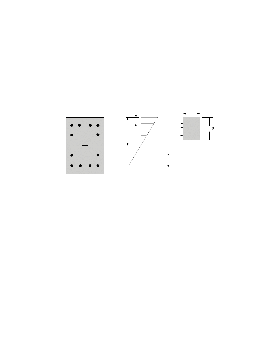
The stress in the steel is given by the product of the steel strain and the steel modu-
lus of elasticity,
e
s
s
E , and is limited to the yield stress of the steel, f
y
(CSA
8.5.3.2). The area associated with each reinforcing bar is assumed to be placed at
the actual location of the center of the bar and the algorithm does not assume any
further simplifications in the manner in which the area of steel is distributed over
the cross section of the column (such as an equivalent steel tube or cylinder). See
Figure V-1.
The concrete compression stress block is assumed to be rectangular, with a stress
value of
a
1
f
c
¢
(CSA 10.1.7). See Figure V-1. The depth of the stress block is
b
1
c,
where
a
1
=
-
¢
0.85 0.0015 f
c
,
a
1
³ 0.67 .
(CSA 10.1.7)
b
1
=
-
¢
0.97
0.0025 f
c
,
b
1
³ 0.67 .
(CSA 10.1.7)
The limit of f
c
¢
is taken to be 80 MPa for Ordinary moment resisting frames and 55
MPa for Nominal and Ductile moment resisting frames:
f
c
¢
£ 80 MPa (Ordinary)
(CSA 8.6.1.1)
f
c
¢
£ 55 MPa (Nominal and Ductile)
(CSA 21.2.3.1)
76
Column Design
SAP2000 Concrete Design Manual
c
d'
C
a =
c
1
2
s
C
1
s
C
ε
c
= 0.0035
ε
s
4
ε
s
3
ε
s
2
ε
s
1
T
s
4
T
s
3
(i) Concrete Section
(ii) Strain Diagram
(iii) Stress Diagram
α
1 c
f'
Figure V-1
Idealization of Stress and Strain Distribution in a Column Section

The limit of f
y
is taken to be 500 MPa for all frames:
f
y
£ 500 MPa.
(CSA 8.5.1)
The interaction algorithm provides a correction to account for the concrete area that
is displaced by the reinforcement in the compression zone.
The effects of the strength reduction factors are included in the generation of the in-
teraction surfaces. The maximum compressive axial load is limited to P
r,max
, where
the maximum factored axial load resistance is given by
P
=
f
A - A
f
A
c
c
g
st
s
y
st
r,max
0.80 [
(
) +
]
j a
j
1
¢
(tied column), (CSA 10.10.4)
P
=
f
A - A
f A
c
c
g
st
s
y
st
r,max
0.85 [
(
) +
]
j a
j
1
¢
(spiral column). (CSA 10.10.4)
Check Column Capacity
The column capacity is checked for each loading combination at each check station
of each column. In checking a particular column for a particular loading combina-
tion at a particular location, the following steps are involved:
• Determine the factored moments and forces from the analysis load cases and
the specified load combination factors to give P
f
, M
fx
, and M
fy
.
• Determine the moment magnification factors for the column moments.
• Apply the moment magnification factors to the factored loads obtained in the
first step. Determine whether the point, defined by the resulting axial load and
biaxial moment set, lies within the interaction volume.
The following three sections describe in detail the algorithms associated with the
above-mentioned steps.
Determine Factored Moments and Forces
The factored loads for a particular load combination are obtained by applying the
corresponding load factors to all the load conditions, giving P
f
, M
fx
, and M
fy
. The
computed moments are further amplified by using “Moment Magnification Fac-
tors” to allow for “Lateral Drift Effect” and “Member Stability Effect”.
Determine Moment Magnification Factors
The moment magnification factors are applied in two different stages. First the mo-
ments are separated into their “sway” and “non-sway” components. The sway com-
ponents are amplified for lateral drift effect (CSA 10.16). Although according to
Column Design
77
Chapter V Design for CSA-A23.3-94
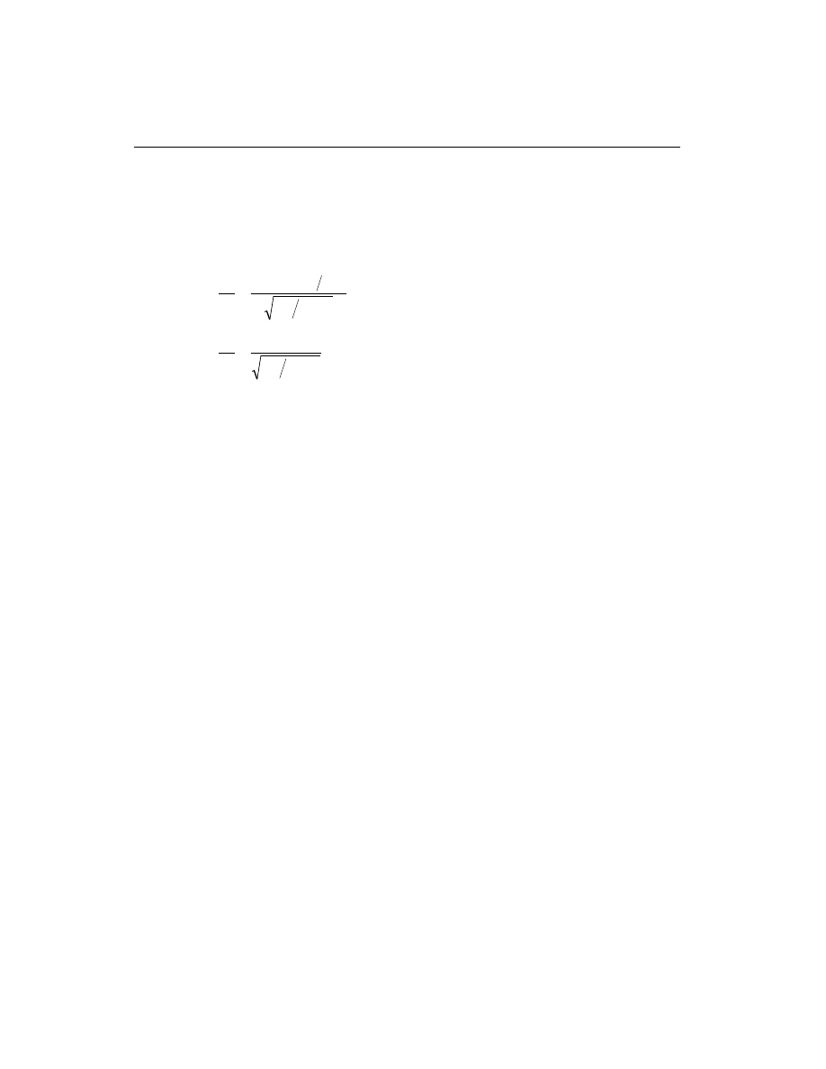
the code, this amplification is significant for “unbraced” frames only and may be
avoided for “braced” frames, SAP2000 treats all frames uniformly to amplify non-
sway components of moments. These amplified moments are further amplified for
individual member stability effect. According to the code, the individual member
stability effect is only significant if
kL
r
M
M
P
f A
f
c
g
³
-
¢
25 10
1
2
, for braced frames, and
(CSA 10.15.2)
kL
r
P
f A
f
c
g
³
¢
35
,
for unbraced frames.
(CSA 10.16.4)
However, SAP2000 considers individual member stability effect for all compres-
sion column elements.
Lateral Drift Effect
For all frames, the moment magnification factor for lateral drift effect is applied
only to the “sway” moment in SAP2000.
M
M
M
ns
s
s
=
+ d
(CSA 10.16.2)
The moment obtained from analysis is separated into two components: the sway
(
)
M
s
and the nonsway (
)
M
ns
components. The non-sway or braced components
which are identified by “ns” subscripts are predominantly caused by gravity load.
The sway components are identified by “s” subscripts. The sway moments are pre-
dominantly caused by lateral loads, and are related to the cause of side sway.
The moment magnification factors in the major and minor directions can, in gen-
eral, be different. The moment magnification factors for moments causing
sidesway,
d
d
sx
sy
and
, can be taken as 1.0 if a P-
D analysis is carried out (CSA
10.16.3.1). The program assumes that a P-
D analysis has been performed in
SAP2000 and, therefore, moment magnification factors for moments causing
sidesway are taken as unity. For the P-
D analysis the load should correspond to a
load combination of (1.25 DL + 1.50 LL)/
j
m
(CSA 10.16.5), where
j
m
is the
strength reduction factor for stability and is equal to 0.75 (CSA 10.15.3). See also
White and Hajjar (1991).
The user is reminded of the special analysis requirements, especially those related
to the value of EI used in analysis (CSA 10.14.1). SAP2000 analysis uses EI of
gross cross-sectional area in conjunction with a multiplication factor. The multipli-
78
Column Design
SAP2000 Concrete Design Manual

cation factors are defined in a section-by-section basis, so that effect of axial force
and cracking can be modeled in a first order analysis.
If the program assumptions are not satisfactory for a particular member, the user
can explicitly specify values of
d
sx
and
d
sy
.
Member Stability Effects
All compression members are designed using the factored axial load, P
f
, from the
analysis and a magnified factored moment, M
c
. The magnified moment is com-
puted as,
M
M
M
c
b
=
³
d
2
2
,
(CSA 10.15.3)
where M
2
is the column maximum end moment obtained from elastic analysis af-
ter considering minimum eccentricity and lateral drift effect, and M
c
is the maxi-
mum moment occurring either at the end or at an interior point within the span of
the column. The moment magnification factor,
d
b
, for moments not causing
sidesway associated with the major or minor direction of the column is given by
d
j
b
m
f
m
c
C
-
P
P
=
³
1
1.0 , where
(CSA 10.15.3)
j
m
= 0.75 ,
(CSA 10.15.3)
P =
EI
kL
c
p
2
2
(
)
,
(CSA 10.15.3)
k is conservatively taken as 1, however the user can override the value,
EI is associated with a particular column direction given by
EI =
E I
c
g
0.25
, and
(CSA 10.15.3)
C
=
+
M
M
m
a
b
0.6
0.4
0.4
³
,
(CSA 10.15.3.1)
M
a
and M
b
are the moments at the ends of the column, and M
b
is numeri-
cally larger than M
a
. M
M
a
b
is positive for single curvature bending and
negative for double curvature bending. The above expression of C
m
is
valid if there is no transverse load applied between the supports. If trans-
verse load is present on the span, or the length is overwritten, or for any
Column Design
79
Chapter V Design for CSA-A23.3-94

other case, C
m
=1 (CSA 10.15.3.2) . C
m
can be overwritten by the user on
an element by element basis.
The pre-magnified factored moments are increased, if required, to obtain minimum
eccentricities, such that C M P
m
f
is at least (
)
15
+ 0.03h mm about each axis sepa-
rately, where h is the dimension of the column in mm unit in the corresponding di-
rection (CSA 10.15.3).
C M
P
h
m
f
³
+
15 0.03
(CSA 10.15.3)
The moment magnification factor,
d
b
, must be a positive number and greater than
one. Therefore P
f
must be less than
j
m
c
P . If P
f
is found to be greater than or equal
to
j
m
c
P , a failure condition is declared.
d
b
is taken as 1 for tension members.
The above calculations use the unsupported length of the column. The two unsup-
ported lengths are l
22
and l
33
corresponding to instability in the minor and major di-
rections of the element, respectively. See Figure II-4. These are the lengths between
the support points of the element in the corresponding directions.
If the program assumptions are not satisfactory for a particular member, the user
can explicitly specify values of
d
d
s
b
and
.
Determine Capacity Ratio
As a measure of the stress condition of the column, a capacity ratio is calculated.
The capacity ratio is basically a factor which gives an indication of the stress condi-
tion of the column with respect to the capacity of the column.
Before entering the interaction diagram to check the column capacity, the moment
magnification factors are applied to the factored loads to obtain P
f
, M
fx
, and M
fy
.
The point (P
f
, M
fx
, M
fy
) is then placed in the interaction space shown as point L in
Figure II-3. If the point lies within the interaction volume, the column capacity is
adequate; however, if the point lies outside the interaction volume, the column is
overstressed.
This capacity ratio is achieved by plotting the point L and determining the location
of point C. The point C is defined as the point where the line OL (if extended out-
wards) will intersect the failure surface. This point is determined by three-
dimensional linear interpolation between the points that define the failure surface.
See Figure II-3. The capacity ratio, CR, is given by the ratio
OL
OC
.
80
Column Design
SAP2000 Concrete Design Manual

• If OL = OC (or CR=1) the point lies on the interaction surface and the column is
stressed to capacity.
• If OL < OC (or CR<1) the point lies within the interaction volume and the col-
umn capacity is adequate.
• If OL > OC (or CR>1) the point lies outside the interaction volume and the col-
umn is overstressed.
The maximum of all the values of CR calculated from each load combination is re-
ported for each check station of the column along with the controlling P
f
, M
fx
, and
M
fy
set and associated load combination number.
If the reinforcing area is not defined, SAP2000 computes the reinforcement that
will give an interaction ratio of unity.
Design Column Shear Reinforcement
The shear reinforcement is designed for each loading combination in the major and
minor directions of the column. In designing the shear reinforcing for a particular
column for a particular loading combination due to shear forces in a particular di-
rection, the following steps are involved:
• Determine the factored forces acting on the section, M
f
, P
f
and V
f
. Note that
M
f
and P
f
are needed for the calculation of v
c
.
• Determine the shear stress, v
c
, that can be resisted by concrete alone.
• Calculate the reinforcement steel required to carry the balance.
For Ductile and Nominal moment resisting concrete frames, the shear design of the
columns is also based upon the probable and nominal moment capacities, respec-
tively, of the members in addition to the factored moments (CSA 21.7.2.2,
21.9.2.3). Effects of the axial forces on the column moment capacities are included
in the formulation.
The following three sections describe in detail the algorithms associated with the
above-mentioned steps.
Determine Section Forces
• In the design of the column shear reinforcement of an Ordinary moment re-
sisting concrete frame, the forces for a particular load combination, namely,
the column axial force, P
f
, the column moment, M
f
, and the column shear
force, V
f
, in a particular direction are obtained by factoring the SAP2000
analysis load cases with the corresponding load combination factors.
Column Design
81
Chapter V Design for CSA-A23.3-94

• In the shear design of Ductile moment resisting frames (seismic design) the
following are checked in addition to the requirement for the Ordinary moment
resisting frames. In the design of Ductile moment resisting concrete frames, the
design shear force, V
f
, in a particular direction is also calculated from the
probable moment capacities of the column associated with the factored axial
force acting on the column (CSA 21.7.2.2).
For each load combination, the factored axial load, P
f
, is calculated. Then, the
positive and negative moment capacities, M
f
+
and M
f
-
, of the column in a par-
ticular direction under the influence of the axial force P
f
are calculated using
the uniaxial interaction diagram in the corresponding direction. The design
shear force, V
f
, is then given by
V
V + V
f
p
D+ L
=
(CSA 21.7.2.2)
where, V
p
is the shear force obtained by applying the calculated probable ulti-
mate moment capacities at the two ends of the column acting in two opposite
directions. Therefore, V
p
is the maximum of V
P
1
and V
P
2
, where
V
=
M
+ M
L
P
I
-
J
+
1
, and
V
=
M
+ M
L
P
I
+
J
-
2
, where
M
I
+
, M
I
-
=
Positive and negative moment capacities at end I of the
column using a steel yield stress value of
af
y
and
no
j factors (j
j
s
c
=
=1.0),
M
J
+
, M
J
-
=
Positive and negative moment capacities at end J of the
column using a steel yield stress value of
af
y
and
no
j factors (j
j
s
c
=
=1.0),
and
L
=
Clear span of column.
For Ductile moment resisting frames
a is taken as 1.25 (CSA 21.1). V
D
L
+
is
the contribution of shear force from the in-span distribution of gravity loads.
For most of the columns, it is zero.
• In the design of Nominal moment resisting frames (seismic), the shear capac-
ity of the column is also checked for the nominal shear due to the nominal
(j
j
s
c
=
=1.0) moment capacities and the factored gravity load (CSA
21.9.2.3), in addition to the design checks required for Ordinary moment resist-
ing frames. The procedure for calculating nominal moment capacity is the
82
Column Design
SAP2000 Concrete Design Manual
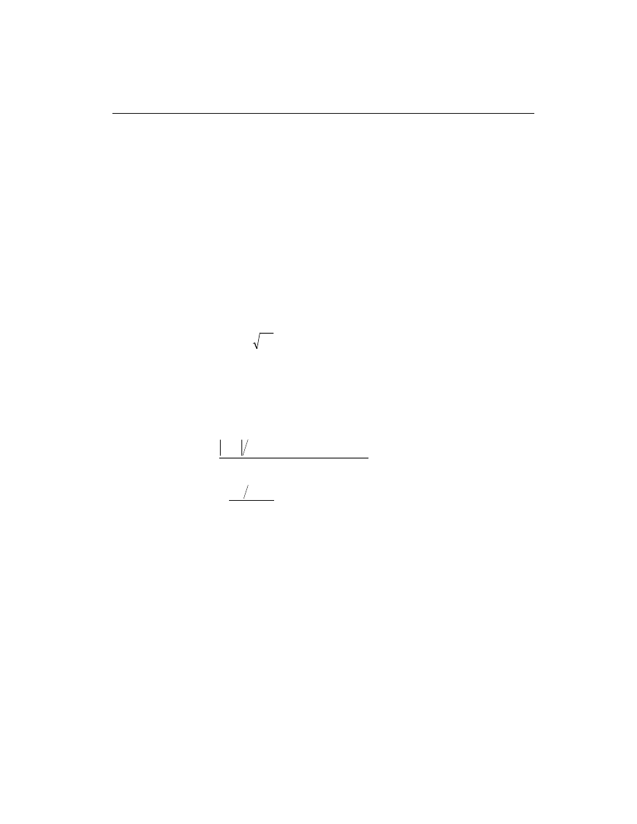
same as that for computing the probable moment capacity for Ductile moment
resisting frames, except that
a is taken equal to 1 (CSA 21.0) rather than 1.25.
The design shear strength is enforced not to be greater than the factored shear
force with the seismic load doubled (CSA 21.9.2.3, 21.9.1). See also Table V-2
for details.
Determine Concrete Shear Capacity
Given the design force set M
f
, P
f
andV
f
, the shear capacity provided by the con-
crete alone, v
c
, is calculated using the “General Method” or “Compression Field
Theory” as follows (CSA 11.4):
• For designing Ordinary and Nominal moment resisting concrete frames, v
c
is set to:
v =
f
c
c
1.3
lb
¢
,
(CSA 11.4.3.1)
where,
b is a factor indicating the ability of diagonally cracked concrete to re-
sist shear. It is a function of stress condition and its average value is 0.2 usually
with a range of 0.1 to 0.4 (CSA 11.4.4). It is computed from CSA Table 11-1
through an iterative procedure. In computing the
bfactor, the following two pa-
rameters are used:
e
q
x
f
v
f
f
s
s
M
d
N
V
E A
=
+
+
0.5
0.5
cot
,
0
0.002
£
£
e
x
(CSA 11.4.6)
v
V
b d
f
ratio
f
w
v
c
c
=
¢
lj
(CSA 11.4.5)
In the above equations d
v
, the distance between the resultants of the tensile and
compressive forces, is conservatively taken to be 0.9d.
d
d
v
= 0.9
(CSA 11.0)
Here
q is an angle of inclination of diagonal compressive stresses. It is a func-
tion of the current stress condition and its approximate value is 34 degrees with
a range of 27 degrees to 45 degrees (CSA 11.4.4). In a similar procedure to cal-
culate the
b factor, q is also computed from CSA Table 11-1 using the parame-
ters
e
x
and v
ratio
through an iterative procedure.
The shear strength factor,
l, is taken to be 1, assuming normal density concrete
(CSA 11.0, 8.6.5).
Column Design
83
Chapter V Design for CSA-A23.3-94
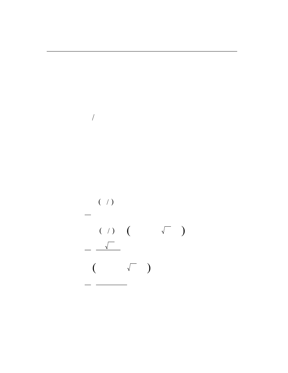
• For designing Ductile moment resisting concrete frames, v
c
is computed
based on the assumption that
e
x
= 0.002 (CSA 21.7.3.1b, 11.4.3.1 ). Otherwise
the procedure for computing v
c
is the same as that for Ordinary and Nominal
moment resisting frames.
Determine Required Shear Reinforcement
• The average shear stress is computed for a rectangular section as,
v = V
b d
f
w
v
(
) .
(CSA 11.4.5)
In the above equation d
v
, the distance between the resultants of the tensile and
compressive forces, is conservatively taken to be 0.9d for rectangular sections.
d
d
v
= 0.9
(CSA 11.0)
For other types of sections b d
w
v
is replaced by 0.9 times A
cv
, the effective
shear area, which is shown in Figure V-2.
• The average shear stress, v, is limited to a maximum limit, v
max
, given by
v
f
c
max
=
¢
0.25
.
(CSA 11.4.3)
• The shear reinforcement per unit spacing is computed as follows:
If v
v
c
£ j
c
2 ,
A
s
v
= 0 ,
(CSA 11.2.8.1)
else if
j
j
j
q
c
c
s
v
v
v
f
c
c
c
2
< £
+
¢
0.06
cot
,
A
s
f b
f
v
c
w
yh
=
¢
0.06
,
(CSA 11.2.8.4)
else if
j
j
q
j
c
s
c
max
v
f
v
v
c
c
+
< £
¢
0.06
cot
,
A
s
v
v
b
f
v
c
w
yh
=
-
(
)
cot
j
j
q
c
s
,
(CSA 11.4.3.2)
else if v
v
> j
c
max
,
a failure condition is declared.
(CSA 11.3.4)
84
Column Design
SAP2000 Concrete Design Manual
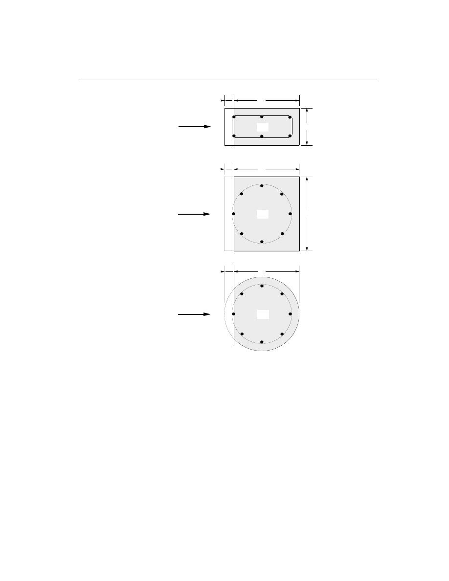
The limit of f
c
¢
is taken to be 80 MPa for Ordinary moment resisting frames and 55
MPa for Nominal and Ductile moment resisting frames:
f
c
¢
£ 80 MPa (Ordinary)
(CSA 8.6.1.1)
f
c
¢
£ 55 MPa (Nominal and Ductile)
(CSA 21.2.3.1)
The limit of f
yh
is taken to be 500 MPa for all frames:
f
yh
£ 500 MPa.
(CSA 8.5.1)
Column Design
85
Chapter V Design for CSA-A23.3-94
SQUARE WITH CIRCULAR REBAR
DIRECTION
OF SHEAR
FORCE
DIRECTION
OF SHEAR
FORCE
DIRECTION
OF SHEAR
FORCE
d
b
d'
RECTANGULAR
Acv
d'
d
b
Acv
d'
CIRCULAR
d
Acv
Figure V-2
Shear Stress Area, A
cv

The maximum of all the calculated A
s
v
values, obtained from each load combina-
tion, is reported for the major and minor directions of the column along with the
controlling shear force and associated load combination number.
For all columns and at any station, the minimum area of transverse circular hoop re-
inforcement is imposed as follows:
A
s
A
A
f
f
h
v
g
core
c
yh
core
³
-
é
ë
ê
ù
û
ú
¢
0.45
1
4
(CSA 10.9.4)
In potential plastic hinge locations, as described later, of Ductile moment resisting
frames, the minimum area of circular hoops and transverse stirrups is imposed as
follows:
A
s
f
f
h
v
c
yh
core
³
¢
0.12
4
(Hoops)
(CSA 21.4.4.2)
A
s
A
A
f
f
h
v
g
core
c
yh
core
³
-
é
ë
ê
ù
û
ú
¢
0.45
1
4
(Hoops)
(CSA 21.4.4.2, 10.9.4)
A
s
f
f
h
v
c
yh
core
³
¢
0.09
(Stirrups)
(CSA 21.4.4.2)
A
s
A
A
f
f
h
v
g
core
c
yh
core
³
-
é
ë
ê
ù
û
ú
¢
0.30
1
(Stirrups)
(CSA 21.4.4.2)
For the definition of the potential plastic hinge, it is assumed in the current version
of the program that any beam and column segment near the joint is a potential plas-
tic hinge. The length of the plastic hinge, L
hinge
, in a column is taken as follows:
L
h b l
hinge
= max , ,
,
6 450 mm
(CSA 21.4.4.5)
The column shear reinforcement requirements reported by the program are based
purely upon the above considerations. Any other minimum stirrup requirements to
satisfy spacing and/or volumetric requirements must be investigated independently
of the program by the user.
86
Column Design
SAP2000 Concrete Design Manual

Beam Design
In the design of concrete beams, SAP2000 calculates and reports the required areas
of steel for flexure and shear based upon the beam moments, shears, load combina-
tion factors and other criteria described below. The reinforcement requirements are
calculated at a user defined number of check stations along the beam span.
All the beams are only designed for major direction flexure and shear. Effects
due to any axial forces, minor direction bending, and torsion that may exist in
the beams must be investigated independently by the user.
The beam design procedure involves the following steps:
• Design beam flexural reinforcement
• Design beam shear reinforcement
Design Beam Flexural Reinforcement
The beam top and bottom flexural steel is designed at a user defined number of de-
sign stations along the beam span. In designing the flexural reinforcement for the
major moment of a particular beam for a particular section, the following steps are
involved:
• Determine the maximum factored moments
• Determine the reinforcing steel
Determine Factored Moments
In the design of flexural reinforcement of Ductile, Nominal, or Ordinary moment
resisting concrete frame beams, the factored moments for each load combination at
a particular beam station are obtained by factoring the corresponding moments for
different load cases with the corresponding load factors. The beam section is then
designed for the maximum positive M
f
+
and maximum negative M
f
-
factored mo-
ments obtained from all of the load combinations
.
Positive beam moments produce bottom steel. In such cases the beam may be de-
signed as a Rectangular- or T-beam. Negative beam moments produce top steel. In
such cases the beam is always designed as a rectangular section.
Beam Design
87
Chapter V Design for CSA-A23.3-94
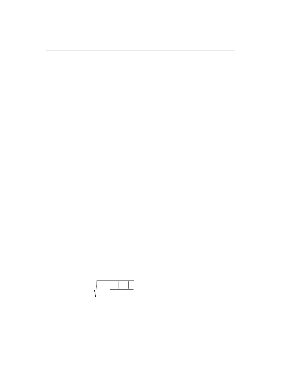
Determine Required Flexural Reinforcement
In the flexural reinforcement design process, the program calculates both the ten-
sion and compression reinforcement. Compression reinforcement is added when
the applied design moment exceeds the maximum moment capacity of a singly re-
inforced section. The user has the option of avoiding the compression reinforce-
ment by increasing the effective depth, the width, or the grade of concrete.
The design procedure is based on the simplified rectangular stress block as shown
in Figure V-3 (CSA 10.1.7). Furthermore it is assumed that the compression carried
by concrete is less than that which can be carried at the balanced condition (CSA
10.1.4). When the applied moment exceeds the moment capacity at the balanced
condition, the area of compression reinforcement is calculated on the assumption
that the additional moment will be carried by compression and additional tension
reinforcement.
In designing the beam flexural reinforcement, the limit of f
c
¢
is taken to be 80 MPa
for Ordinary moment resisting frames and 55 MPa for Nominal and Ductile mo-
ment resisting frames:
f
c
¢
£ 80 MPa (Ordinary)
(CSA 8.6.1.1)
f
c
¢
£ 55 MPa (Nominal and Ductile)
(CSA 21.2.3.1)
The limit of f
y
is taken to be 500 MPa for all frames:
f
y
£ 500 MPa.
(CSA 8.5.1)
The design procedure used by SAP2000 for both rectangular and flanged sections
(L- and T-beams) is summarized below. It is assumed that the design ultimate axial
force in a beam is negligible, hence all the beams are designed for major direction
flexure and shear only.
Design for Flexure of a Rectangular Beam
In designing for a factored negative or positive moment, M
f
, (i.e. designing top or
bottom steel) the depth of the compression block is given by a, as shown in Figure
V-3, where,
a
d
d
M
f
b
f
c
c
= -
-
¢
2
1
2
a
j
,
(CSA 10.1)
where the value of
j
c
is 0.60 (CSA 8.4.2) in the above and following equations.
Also
a
1
,
b
1
, and c
b
are calculated as follows:
88
Beam Design
SAP2000 Concrete Design Manual
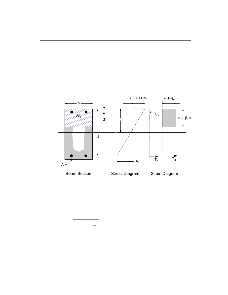
a
1
=
f
c
0.85
0.0015
0.67
-
³
¢
,
(CSA 10.1.7)
b
1
=
f
c
0.97
0.0025
0.67
-
³
¢
, and
(CSA 10.1.7)
c =
+ f
d
b
y
700
700
.
(CSA 10.5.2)
The balanced depth of the compression block is given by
a
c
b
b
= b
1
.
(CSA 10.1.7)
• If a
a
b
£
(CSA 10.5.2), the area of tensile steel reinforcement is then given
by
A
M
f
d
a
s
f
s
y
=
-
æ
è
ç
ö
ø
÷
j
2
.
This steel is to be placed at the bottom if M
f
is positive, or at the top if M
f
is
negative.
Beam Design
89
Chapter V Design for CSA-A23.3-94
Figure V-3
Design of a Rectangular Beam Section
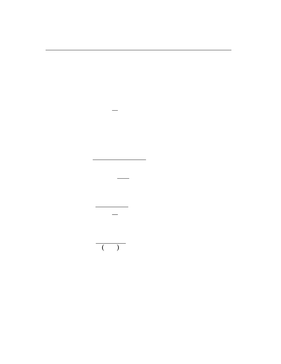
• If a
a
b
>
(CSA 10.5.2), compression reinforcement is required and is calcu-
lated as follows:
– The factored compressive force developed in the concrete alone is given by
C
f ba
c
c
b
=
¢
j a
1
, and
(CSA 10.1.7)
the factored moment resisted by the concrete and bottom steel is
M
C d
a
fc
b
=
-
æ
è
ç
ö
ø
÷
2
.
– The moment resisted by compression steel and tensile steel is
M
M
M
fs
f
fc
=
-
.
– So the required compression steel is given by
A
M
f
f
d
d
s
fs
s
s
c
c
¢
¢
¢
=
-
- ¢
(
)(
)
j
j a
1
, where
f
E
c
d
c
f
s
s
y
¢
=
- ¢
é
ëê
ù
ûú
£
0.0035
.
(CSA 10.1.2 and CSA 10.1.3)
– The required tensile steel for balancing the compression in concrete is
A
M
f
d
a
s
fc
y
b
s
1
2
=
-
æ
è
ç
ö
ø
÷ j
, and
the tensile steel for balancing the compression in steel is
A
M
f
d
d
s
fs
y
s
2
=
- ¢ j
.
– Therefore, the total tensile reinforcement, A
A
A
s
s
s
=
+
1
2
, and total com-
pression reinforcement is A
s
¢
. A
s
is to be placed at the bottom and A
s
¢
is to be
placed at the top if M
f
is positive, and vice versa.
90
Beam Design
SAP2000 Concrete Design Manual

Design for Flexure of a T-Beam
(i) Flanged Beam Under Negative Moment
In designing for a factored negative moment, M
f
, (i.e. designing top steel), the
contribution of the flange to the strength of the beam is ignored. The design proce-
dure is therefore identical to the one used for rectangular beams except that in the
corresponding equations b is replaced by b
w
.
(ii) Flanged Beam Under Positive Moment
If M
f
> 0, the depth of the compression block is given by (see Figure V-4).
a
d
d
M
f
b
f
c
c
f
= -
-
¢
2
1
2
a
j
.
(CSA 10.1)
where the value of
j
c
is 0.60 (CSA 8.4.2) in the above and following equations. See
Figure V-4. Also
a
1
,
b
1
, and c
b
are calculated as follows:
a
1
=
f
c
0.85
0.0015
0.67
-
³
¢
,
(CSA 10.1.7)
b
1
=
f
c
0.97
0.0025
0.67
-
³
¢
, and
(CSA 10.1.7)
c =
+ f
d
b
y
700
700
.
(CSA 10.5.2)
The depth of the compression block under balanced condition is given by
a
c
b
b
= b
1
.
(CSA 10.1.7)
• If a
d
s
£ , the subsequent calculations for A
s
are exactly the same as previously
done for the rectangular section design. However, in this case the width of the
beam is taken as b
f
. Whether compression reinforcement is required depends
on whether a
a
b
> .
• If a
d
s
> , calculation for A
s
is done in two parts. The first part is for balancing
the compressive force from the flange, C
f
, and the second part is for balancing
the compressive force from the web, C
w
. As shown in Figure V-4,
C
f
b
b
d
f
c
f
w
s
=
-
¢
a
1
(
)
.
(CSA 10.1.7)
Therefore, A =
C
f
s
f
c
y
s
1
j
j
and the portion of M
f
that is resisted by the flange is
Beam Design
91
Chapter V Design for CSA-A23.3-94
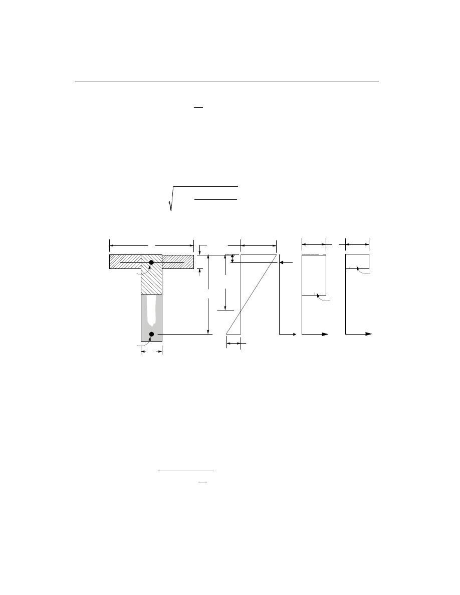
M
= C
d
d
ff
f
s
c
-
æ
è
ç
ö
ø
÷
2
j .
Therefore, the balance of the moment, M
f
to be carried by the web is given by
M
= M
M
fw
f
ff
-
.
The web is a rectangular section of dimensions b
w
and d, for which the depth of
the compression block is recalculated as
a
d
d
M
f
b
fw
c
c
w
1
2
1
2
= -
-
¢
a
j
.
(CSA 10.1)
• If a
a
b
1
£
(CSA 10.5.2), the area of tensile steel reinforcement is then
given by
A
M
f
d
a
s
fw
s
y
2
1
2
=
-
æ
è
ç
ö
ø
÷
j
, and
92
Beam Design
SAP2000 Concrete Design Manual
c
b
f
d
A
s
= 0.0035
ε
ε
s
d
s
b
w
A
s
'
C
s
T
s
d'
f
s
'
C
f
T
f
C
w
T
w
Beam Section
Stress Diagram
Strain Diagram
α φ
1 c
c
f '
α φ
1 c
c
f '
Figure V-4
Design of a T-Beam Section

A
A
A
s
s
s
=
+
1
2
.
This steel is to be placed at the bottom of the T-beam.
• If a
a
b
1
>
(CSA 10.5.2), compression reinforcement is required and is cal-
culated as follows:
– The factored compressive force in the concrete web alone is given by
C
f ba
c
c
b
=
¢
j a
1
, and
(CSA 10.1.7)
the factored moment resisted by the concrete web and tensile steel is
M
C d
a
fc
b
=
-
æ
è
ç
ö
ø
÷
2
.
– The moment resisted by compression steel and tensile steel is
M
M
M
fs
fw
fc
=
-
.
– Therefore, the compression steel is computed as
A
M
f
f
d
d
s
fs
s
s
c
c
¢
¢
¢
=
-
- ¢
(
)(
)
j
j a
1
, where
f
E
c
d
c
f
s
s
y
¢
=
- ¢
é
ëê
ù
ûú
£
0.0035
.
(CSA 10.1.2 and CSA 10.1.3)
– The tensile steel for balancing compression in web concrete is
A
M
f
d
a
s
fc
y
b
s
2
2
=
-
æ
è
ç
ö
ø
÷ j
, and
the tensile steel for balancing compression in steel is
A
M
f
d
d
s
fs
y
s
3
=
- ¢
(
)
j
.
Total tensile reinforcement, A
A
A
A
s
s
s
s
=
+
+
1
2
3
, and total compression rein-
forcement is A
s
¢
. A
s
is to be placed at the bottom and A
s
¢
is to be placed at the top.
Beam Design
93
Chapter V Design for CSA-A23.3-94
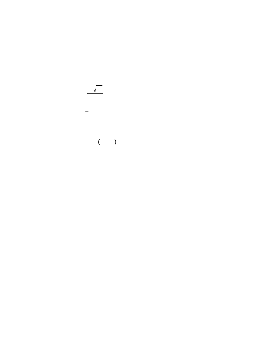
Minimum and Maximum Tensile Reinforcement
The minimum flexural tensile steel required for a beam section is given by the mini-
mum of the two limits:
A
f
f
b h
s
c
y
w
³
¢
0.2
, or
(CSA 10.5.1.2)
A
A
s
s required
³
4
3
(
)
.
(CSA 10.5.1.3)
In addition, the minimum flexural tensile steel provided in a T-section with flange
under tension is given by the limit:
A
b
b
d
s
w
s
³
-
0.004
.
(CSA 10.5.3.1)
An upper limit of 0.04 times the gross web area on both the tension reinforcement
and the compression reinforcement is arbitrarily imposed as follows:
A
b d
b d
s
w
£ ìí
î
0.04
Rectangular beam
0.04
T -beam
A
b d
b d
s
w
¢
£ ìí
î
0.04
Rectangular beam
0.04
T -beam
Special Consideration for Seismic Design
For Ductile moment resisting concrete frames (seismic design), the beam design
satisfies the following additional conditions (see also Table V-2 for comprehensive
listing):
• The minimum longitudinal reinforcement shall be provided at both the top and
the bottom. Any of the top and bottom reinforcement shall not be less than
A
s min
(
)
.
A
f
b d
y
w
s(min)
³
1.4
(CSA 21.3.2.1)
• The beam flexural steel is limited to a maximum given by
A
b d
s
w
£ 0.025
.
(CSA 21.3.2.1)
94
Beam Design
SAP2000 Concrete Design Manual

• At any end (support) of the beam, the beam positive moment capacity (i.e. as-
sociated with the bottom steel) would not be less than ½ of the beam negative
moment capacity (i.e. associated with the top steel) at that end (CSA 21.3.2.2).
• Neither the negative moment capacity nor the positive moment capacity at any
of the sections within the beam would be less than 1/4 of the maximum of posi-
tive or negative moment capacities of any of the beam end (support) stations
(CSA 21.3.2.2).
For Nominal moment resisting concrete frames (seismic design), the beam design
would satisfy the following conditions:
• At any support of the beam, the beam positive moment capacity would not be
less than 1/3 of the beam negative moment capacity at that end (CSA
21.9.2.1.1).
• Neither the negative moment capacity nor the positive moment capacity at any
of the sections within the beam would be less than 1/5 of the maximum of posi-
tive or negative moment capacities of any of the beam end (support) stations
(CSA 21.9.2.1.1).
Design Beam Shear Reinforcement
The shear reinforcement is designed for each load combination at a user defined
number of stations along the beam span. In designing the shear reinforcement for a
particular beam for a particular loading combination at a particular station due to
the beam major shear, the following steps are involved:
• Determine the factored forces acting on the section, M
f
and V
f
. Note that M
f
is needed for the calculation of v
c
.
• Determine the shear stress, v
c
, that can be resisted by concrete alone.
• Calculate the reinforcement steel required to carry the balance.
For Ductile and Nominal moment resisting frames, the shear design of the beams is
also based on the probable and nominal moment capacities of the members, respec-
tively (CSA 21.7.2.1, 21.9.2.3).
The following three sections describe in detail the algorithms associated with the
above-mentioned steps.
Beam Design
95
Chapter V Design for CSA-A23.3-94
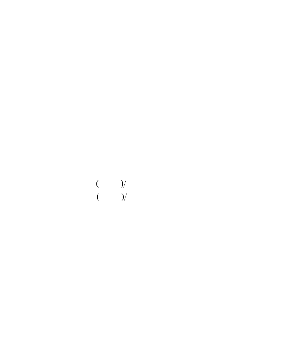
Determine Shear Force and Moment
• In the design of the beam shear reinforcement of an Ordinary moment resist-
ing concrete frame, the shear forces and moments for a particular load combi-
nation at a particular beam section are obtained by factoring the associated
shear forces and moments with the corresponding load combination factors.
• In the design of Ductile moment resisting concrete frames (seismic design),
the shear capacity of the beam is also checked for the probable shear due to the
probable moment capacities and the factored gravity load, in addition to the de-
sign checks required for Ordinary moment resisting frames. The procedure for
calculating the design shear force in a beam from probable moment capacities
is the same as that described for a column in section “Column Design” on page
82. See also Table V-2 for more details. The design shear forceV
f
is then given
by
V
V + V
f
p
D+ L
=
(CSA 21.7.2.1)
where, V
p
is the shear force obtained by applying the calculated probable ulti-
mate moment capacities at the two ends of the beams acting in two opposite di-
rections. Therefore, V
p
is the maximum of V
P
1
and V
P
2
, where
V
=
M
+ M
L
P
I
-
J
+
1
, and
V
=
M
+ M
L
P
I
+
J
-
2
, where
M
I
+
= Moment capacity at end I, with bottom steel in tension, using a steel
yield stress value of
af
y
and no
j factors (j
j
s
c
=
=1.0),
M
J
+
= Moment capacity at end J, with bottom steel in tension, using a steel
yield stress value of
af
y
and no
j factors (j
j
s
c
=
=1.0),
M
I
-
= Moment capacity at end I, with top steel in tension, using a steel yield
stress value of
af
y
and no
j factors (j
j
s
c
=
=1.0),
M
J
-
= Moment capacity at end J, with top steel in tension, using a steel yield
stress value of
af
y
and no
j factors (j
j
s
c
=
=1.0), and
L
= Clear span of beam.
The overstrength factor
a is always taken as 1.25 for Ductile moment resisting
frames (CSA 21.1).V
D
L
+
is the contribution of shear force from the in-span dis-
tribution of gravity loads.
96
Beam Design
SAP2000 Concrete Design Manual
• In the design of Nominal moment resisting frames (seismic), the shear capac-
ity of the beam is also checked for the nominal shear due to the nominal
(j
j
s
c
=
=1.0) moment capacities and the factored gravity load (CSA
21.9.2.3), in addition to the design checks required for Ordinary moment resist-
ing frames. The procedure for calculating nominal moment capacity is the
same as that for computing the probable moment capacity for Ductile moment
resisting frames, except that
a is taken equal to 1 (CSA 21.1) rather than 1.25.
The design shear strength is enforced not to be greater than the factored shear
force with the seismic load doubled (CSA 21.9.2.3, 21.9.1). See also Table V-2
for details.
Determine Concrete Shear Capacity
Given the design force set M
f
and V
f
, the shear capacity provided by the concrete
alone, v
c
, is calculated using the “General Method” or “Compression Field The-
ory” as follows (CSA 11.4):
• For designing Ordinary and Nominal moment resisting concrete frames, v
c
is set to:
v =
f
c
c
1.3
lb
¢
,
(CSA 11.4.3.1)
where,
b is a factor indicating the ability of diagonally cracked concrete to re-
sist shear. It is a function of the stress condition and its average value is 0.2 usu-
ally with a range of 0.1 to 0.4 (CSA 11.4.4). It is computed from CSA Table
11-1 through an iterative procedure. In computing the
b factor, the following
two parameters are used:
e
q
x
f
v
f
s
s
M
d
V
E A
=
+ 0.5
cot
,
0
£
£
e
x
0.002
(CSA 11.4.6)
v
V
b d
f
ratio
f
w
v
c
c
=
¢
lj
(CSA 11.4.5)
In the above equations d
v
, the distance between the resultants of the tensile and
compressive forces, is conservatively taken to be 0.9d.
d
d
v
= 0.9
(CSA 11.0)
Here
q is an angle of inclination of diagonal compressive stresses. It is a func-
tion of the current stress condition and its approximate value is 34 degrees with
a range of 27 degrees to 45 degrees (CSA 11.4.4). In a similar procedure to cal-
Beam Design
97
Chapter V Design for CSA-A23.3-94
culate the
b factor, q is also computed from CSA Table 11-1 using the parame-
ters
e
x
and v
ratio
through an iterative procedure.
The shear strength factor,
l, is taken to be 1, assuming normal density concrete
(CSA 11.0, 8.6.5).
• For designing Ductile moment resisting concrete beams, v
c
is taken as zero,
b is taken as zero, and q is taken as 45 degrees (CSA 21.7.3.1a, 11.4.3.1 ).
Determine Required Shear Reinforcement
• The average shear stress is computed for a rectangular section as,
v =
V
b d
f
w
v
.
(CSA 11.4.5)
In the above equation d
v
, the distance between the resultants of the tensile and
compressive forces, is conservatively taken to be 0.9d.
d
d
v
= 0.9
(CSA 11.0)
For other types of sections b d
w
v
is replaced by 0.9 times A
cv
, the effective
shear area, which is shown in Figure V-2.
• The average shear stress, v, is limited to a maximum limit, v
max
, given by
v
f
c
max
=
¢
0.25
.
(CSA 11.4.3)
• The shear reinforcement per unit spacing is computed as follows:
If v
v
c
£ j
c
2 ,
A
s
v
= 0 ,
(CSA 11.2.8.1)
else if
j
j
j
q
c
c
s
v
v
v
f
c
c
c
2
< £
+
¢
0.06
cot
,
A
s
f b
f
v
c
w
yh
=
¢
0.06
,
(CSA 11.2.8.4)
98
Beam Design
SAP2000 Concrete Design Manual

else if
j
j
q
j
c
s
c
max
v
f
v
v
c
c
+
< £
¢
0.06
cot
,
A
s
v
v
b
f
v
c
w
yh
=
-
(
)
cot
j
j
q
c
s
,
(CSA 11.4.3.2)
else if v
v
> j
c
max
,
a failure condition is declared.
(CSA 11.3.4)
The limit of f
c
¢
is taken to be 80 MPa for Ordinary moment resisting frames and 55
MPa for Nominal and Ductile moment resisting frames:
f
c
¢
£ 80 MPa (Ordinary)
(CSA 8.6.1.1)
f
c
¢
£ 55 MPa (Nominal and Ductile)
(CSA 21.2.3.1)
The limit of f
yh
is taken to be 500 MPa for all frames:
f
yh
£ 500 MPa.
(CSA 8.5.1)
The maximum of all the calculated A
s
v
values, obtained from each load combina-
tion, is reported for the major directions of the beam along with the controlling
shear force and associated load combination number.
The beam shear reinforcement requirements reported by the program are based
purely upon the above considerations. Any other minimum stirrup requirements to
satisfy spacing and/or volumetric requirements must be investigated independently
of the program by the user.
Beam Design
99
Chapter V Design for CSA-A23.3-94
100
Beam Design
SAP2000 Concrete Design Manual
Type of
Check/
Design
Ordinary Moment
Resisting Frames
(non-Seismic)
Nominal Moment Resisting
Frames
(Seismic)
Ductile Moment
Resisting Frames
(Seismic)
Strength of
materials
f
c
¢
£ 80 MPa
f
y
£ 500 MPa
f
c
¢
£ 55 MPa
f
y
£ 500 MPa
f
c
¢
£ 55 MPa
f
y
£ 500 MPa
Column
Check
(interaction)
NLD
a
Combinations
NLD
a
Combinations
NLD
a
Combinations
Column
Design
(Interaction)
NLD
a
Combinations
1% <
ρ
< 8%
NLD
a
Combinations
1% <
ρ
< 8%
NLD
a
Combinations
1% <
ρ
< 6%
α
= 1.0
Column
Shears
NLD
a
Combinations
Minimum hoop
Modified NLD
a
Combinations
or Nominal Capacity Shear (V
p
)
ϕ
= 1.0 and
α
= 1.0
Minimum hoop reinforcement
NLD
a
Combinations and
Probable Capacity Shear (V
p
)
ϕ
= 1.0 and
α
= 1.25
Strength based on
e
x
= 0.002
Minimum hoop reinforcement
Special reinforcement in hinge
Beam
Design
Flexure
NLD
a
Combinations
r £ 0.04
r ³
¢
0.2
f
f
c
y
NLD
a
Combinations
r £ 0.04
r ³
¢
0.2
f
f
c
y
NLD
a
Combinations
r £ 0.025
r ³
¢
0.2
f
f
c
y
,
r ³ 14
.
f
y
Beam Min.
Moment
Override
Check
No Requirement
M
M
uEND
+
uEND
-
³
1
3
{
}
M
M
M
uSPAN
+
u
+
u
END
³
-
1
5
max
,
{
}
M
M
M
uSPAN
u
+
u
END
-
-
³
1
5
max
,
M
M
uEND
+
uEND
-
³
1
2
{
}
M
M
M
uSPAN
+
u
+
u
END
³
-
1
4
max
,
{
}
M
M
M
uSPAN
u
+
u
END
-
-
³
1
4
max
,
Beam Design
Shear
NLD
a
Combinations
Modified NLD
a
Combinations
or Nominal Capacity Shear (V
p
)
with
α
= 1.0 and
ϕ
= 1.0
plus V
D L
+
NLD
a
Combinations and
Probable Capacity Shear (V
p
)
with
α
= 1.25 and
ϕ
= 1.0
plus V
D+L
Strength based on
b = 0 ,
q = 45
o
a
NLD = Number of specified loading
Table V-2
Comparison of Ordinary, Ductile, and Nominal Moment Resisting Frame Design

C h a p t e r VI
Design for BS 8110-85 R1989
This chapter describes in detail the various aspects of the concrete design procedure
that is used by SAP2000 when the user selects the British limit state design code BS
8110 R1989 (BSI 1989). Various notations used in this chapter are listed in Table
VI-1.
The design is based on user-specified loading combinations. But the program pro-
vides a set of default load combinations that should satisfy requirements for the de-
sign of most building type structures.
English as well as SI and MKS metric units can be used for input. But the code is
based on Newton-Millimeter-Second units. For simplicity, all equations and de-
scriptions presented in this chapter correspond to Newton-Millimeter-Second
units unless otherwise noted.
Design Load Combinations
The design loading combinations define the various factored combinations of the
load cases for which the structure is to be checked. The design loading combina-
tions are obtained by multiplying the characteristic loads by appropriate partial fac-
tors of safety,
g
f
(BS 2.4.1.3). If a structure is subjected to dead load (DL) and live
load (LL) only, the design will need only one loading combination, namely 1.4 DL
+ 1.6 LL. However, in addition to the dead load and live load, if the structure is sub-
Design Load Combinations
101
102
Design Load Combinations
SAP2000 Concrete Design Manual
A
cv
Area of section for shear resistance, mm
2
A
s
Area of tension reinforcement, mm
2
A
s
¢
Area of compression reinforcement, mm
2
A
sc
Total area of column longitudinal reinforcement, mm
2
A
sv
Total cross-sectional area of links at the neutral axis, mm
2
a
Depth of compression block, mm
b
Width or effective width of the section in the compression zone, mm
b
¢
Shorter section dimension, mm
Shorter effective depth of biaxially bent column, mm
b
f
Width or effective width of flange, mm
b
w
Average web width of a flanged beam, mm
C
Compression force, N
d
Effective depth of tension reinforcement, mm
d
¢
Depth to center of compression reinforcement, mm
E
c
Modulus of elasticity of concrete, MPa
E
s
Modulus of elasticity of reinforcement, assumed as 200000 MPA
(BS 2.4.2.3)
e
min
Minimum or nominal eccentricity, mm
f
cu
Characteristic cube strength at 28 days, MPA
f
s
¢
Compressive stress in a beam compression steel, MPA
f
y
Characteristic strength of reinforcement, MPA
f
yv
Characteristic strength of link reinforcement, MPA (< 460 MPA)
h
Overall depth of a section in the plane of bending, mm
h
f
Flange thickness, mm
K
¢
Maximum
M
bd f
u
cu
2
for a singly reinforced concrete section taken as 0.156
by assuming that moment redistribution is limited to 10%
k
1
Shear strength enhancement factor
k
2
Concrete shear strength factor, f
cu
25
1 3
/
l
e
Effective height of a column, mm
Table VI-1
List of Symbols Used in the BS code

Design Load Combinations
103
Chapter VI Design for BS 8110-85 R1989
l
0
Clear height between end restraints, mm
M
Design moment at a section, MPA
M
M
1
2
,
Smaller and larger end moments in a slender column, N-mm
M
add
Maximum additional moment column, N-mm
M
i
Initial moment at the point of maximum additional moment, N-mm
M
M
x
y
,
Applied moments about the major and minor axes of a column, N-mm
N
Ultimate axial load, N
s
v
Spacing of links, mm
T
Tension force, N
V
Shear force at ultimate design load, N
v
Shear stress, MPA
v
c
Design ultimate shear stress resistance of a concrete beam, MPA
v
c
¢
Design concrete shear stress corrected for axial forces, MPA
v
v
x
y
,
Design ultimate shear stress of a concrete section, MPA
x
Neutral axis depth, mm
x
bal
Depth of neutral axis in a balanced section, mm
z
Lever arm, mm
b
Effective length factor
b
b
Moment redistribution factor in a member
g
f
Partial safety factor for load
g
m
Partial safety factor for material strength
e
c
Concrete strain
e
s
Strain in tension steel
e
s
¢
Strain in compression steel
Table VI-1
List of Symbols Used in the BS code (continued)

jected to wind (WL) and/or earthquake (EL) loads, and considering that those loads
are subject to reversals, the following load combinations for ultimate limit state
might have to be considered (BS 2.4.3):
1.4 DL
1.4 DL + 1.6 LL
(BS 2.4.3)
1.0 DL
± 1.4 WL
1.4 DL
± 1.4 WL
1.2 DL + 1.2 LL
± 1.2 WL
(BS 2.4.3)
1.0 DL
± 1.4 EL
1.4 DL
± 1.4 EL
1.2 DL + 1.2 LL
± 1.2 EL
These are the default load combinations. In addition to the above load combina-
tions, the code requires that all buildings should be capable of resisting a notional
design ultimate horizontal load applied at each floor or roof level. The notional load
should be equal to 0.015 times the dead load (BS 3.1.4.2). It is recommended that
the user define additional load cases for considering the notional load in SAP2000.
Live load reduction factors, as allowed by some design codes, can be applied to the
member forces of the live load case on a member-by-member basis to reduce the
contribution of the live load to the factored loading.
Design Strength
The design strength for concrete and steel are obtained by dividing the characteris-
tic strength of the material by a partial factor of safety,
g
m
. The values of
g
m
used in
the program are listed below (BS 2.4.4.1).
g
m
=
1.15, for reinforcement,
1.50, for concrete in flexure and axial load, and
1.25, for shear strength without shear reinforcement.
ì
í
ï
îï
(BS 2.4.4.1)
Column Design
The user may define the geometry of the reinforcing bar configuration of each con-
crete column section. If the area of reinforcing is provided by the user, the program
checks the column capacity. However, if the area of reinforcing is not provided by
the user, the program calculates the amount of reinforcing required for the column.
104
Design Strength
SAP2000 Concrete Design Manual

The design procedure for the reinforced concrete columns of the structure involves
the following steps:
• Generate axial force/biaxial moment interaction surfaces for all of the different
concrete section types of the model. A typical biaxial interaction surface is
shown in Figure II-1. When the steel is undefined, the program generates the
interaction surfaces for the range of allowable reinforcement from 0.4 to 6 per-
cent (BS 3.12.5.3 and BS 3.12.6.2).
• Calculate the capacity ratio or the required reinforcing area for the factored ax-
ial force and biaxial (or uniaxial) bending moments obtained from each loading
combination at each station of the column. The target capacity ratio is taken as
one when calculating the required reinforcing area.
• Design the column shear reinforcement.
The following three subsections describe in detail the algorithms associated with
the above-mentioned steps.
Generation of Biaxial Interaction Surfaces
The column capacity interaction volume is numerically described by a series of dis-
crete points that are generated on the three-dimensional interaction failure surface.
In addition to axial compression and biaxial bending, the formulation allows for ax-
ial tension and biaxial bending considerations (BS 3.8.4.1). A typical interaction
diagram is shown in Figure II-1.
The coordinates of these points are determined by rotating a plane of linear strain in
three dimensions on the section of the column (BS 3.4.4.1). See Figure II-2. The
linear strain diagram limits the maximum concrete strain,
e
c
, at the extremity of the
section, to 0.0035 (BS 3.4.4.1).
The formulation is based consistently upon the basic principles of ultimate strength
design and allows for any doubly symmetric rectangular, square, or circular column
section (BS 3.8.4).
The stress in the steel is given by the product of the steel strain and the steel modu-
lus of elasticity,
e
s
s
E and is limited to the design strength the steel, f
y
1.15
(0.87 f
y
). The area associated with each reinforcing bar is placed at the actual loca-
tion of the center of the bar and the algorithm does not assume any simplifications
in the manner in which the area of steel is distributed over the cross section of the
column (such as an equivalent steel tube or cylinder). See Figure VI-1.
Column Design
105
Chapter VI Design for BS 8110-85 R1989

The concrete compression stress block is assumed to be rectangular, with a stress
value of 0.67
0.45
f
f
cu
m
cu
g =
(BS 3.4.4.1). See Figure VI-1. The interaction algo-
rithm provides corrections to account for the concrete area that is displaced by the
reinforcement in the compression zone.
Check Column Capacity
The column capacity is checked for each loading combination at each output station
of each column. In checking a particular column for a particular loading combina-
tion at a particular location, the following steps are involved:
• Determine the factored moments and forces from the analysis load cases and
the specified load combination factors to give N V V
M
M
x
y
x
y
,
,
,
, and
.
• Determine the additional moments due to slender column effect. Compute mo-
ments due to minimum eccentricity.
• Determine total design moments by adding the corresponding additional mo-
ments to the factored moments obtained from the analysis. Determine whether
the point, defined by the resulting axial load and biaxial moment set, lies within
the interaction volume.
106
Column Design
SAP2000 Concrete Design Manual
d'
C
3
s
T
4
s
T
(iii) STRESS
DIAGRAM
(ii) STRAIN
DIAGRAM
(i) CONCRETE
SECTION
2
s
C
1
s
C
ε
c
= 0.0035
ε
s
1
ε
s
2
ε
s
3
ε
s
4
x
a = 0.9 x
0.67 f /
cu
m
γ
Figure VI-1
Idealized Stress and Strain Distribution in a Column Section

The following three subsections describe in detail the algorithms associated with
the above-mentioned steps.
Determine Factored Moments and Forces
Each load combination is defined with a set of load factors corresponding to the
load cases. The factored loads for a particular load combination are obtained by ap-
plying the corresponding load factors to the load cases, giving N V V
x
y
,
,
, M
x
and
M
y
.
Determine Additional Moments
The determination of additional moments depends on whether the frame is
“braced” or “unbraced” against side-sway (BS 3.8.1.5). For “unbraced” columns
additional moment is automatically considered in the P-
D analysis. But for
“braced” columns, further calculation is required for stability of individual column
members.
Braced Column
The additional moment in a braced column in a particular plane is the product of the
axial load and the lateral deflection of the column in that plane (BS 3.8.3),
M
= N a
add
u
,
(BS 3.8.3.1)
where, a
u
is the deflection at the ultimate limit state which is obtained from
a
Kh
u
e
=
b
and
(BS 3.8.3.1)
b
e
e
l
b
=
1
2000
2
¢
æ
è
ç
ö
ø
÷ .
(BS 3.8.3.1)
In the above equations,
• l
e
is the effective length in the plane under consideration. It is obtained from
l =
l
e
b
0
,
(BS 3.8.1.6.1)
where
bis the effective length factor, and l
0
the unsupported length correspond-
ing to instability in the major or minor direction of the element, l
l
x
y
or
in
Figure II-4. In calculating the value of the effective length, the
b factor is con-
servatively taken as 1. However, SAP2000 allows the user to override this de-
fault value.
• b
¢ is the dimension of the column in the plane of bending considered,
Column Design
107
Chapter VI Design for BS 8110-85 R1989

• h is also the dimension of the column in the plane of bending considered, and
• K is the correction factor to the deflection to take care of the influence of the
axial force and K is conservatively taken as 1.
SAP2000 then calculates the total design moments by combining the factored mo-
ments obtained from analysis and the additional moments. If M
1
and M
2
(
)
M
M
2
1
>
are the initial end moments in a column member in a particular plane,
then the maximum design moment for the column is taken as the greatest of the fol-
lowing:
M
2
(BS 3.8.3.2)
M + M
add
1
(BS 3.8.3.2)
M + M
/
i
add
2
(BS 3.8.3.2)
N e
min
(BS 3.8.3.2)
where,
M
i
is the initial moment in a column due to design ultimate loads at the point of
maximum additional moment and is given by
M
M +
M
M
i
=
³
0.4
0.6
0.4
1
2
2
.
(BS 3.8.3.2)
M
1
and M
2
are the smaller and the larger end moments respectively. Both mo-
ments are assumed to be positive if the column is in single curvature. If the col-
umn is in double curvature, M
1
is assumed to be negative.
e
min
is the minimum eccentricity which is taken as 0.05 times the overall di-
mension of the column in the plane of bending considered but not more than 20
mm (BS 3.8.2.4).
e
h
min
=
£
20
20 mm
(BS 3.8.2.4)
Unbraced Column
In the case of the unbraced column, it is assumed that the SAP2000 analysis in-
cludes P-
D effects so that the analysis results include the effects of the additional
moments. Therefore, no additional computation is required. That means moment
magnification factors for moments causing sidesway are taken as unity. However,
it is recommended that for P-
D analysis a factor be used to obtain a P equivalent to
1.2 DL + 1.2 LL (White and Hajjar 1991).
108
Column Design
SAP2000 Concrete Design Manual

Also, the minimum eccentricity requirements are satisfied so the design moment
should at least be
M
N e
u
³
min
,
(BS 3.8.3.2)
where, e
min
is the minimum eccentricity which is described in the previous section.
In biaxial bending the algorithm ensures that the eccentricity exceeds the minimum
about both the axes simultaneously.
Determine Capacity Ratio
As a measure of the stress condition of the column, a capacity ratio is calculated.
The capacity ratio is basically a factor that gives an indication of the stress condi-
tion of the column with respect to the capacity of the column.
Before entering the interaction diagram to check the column capacity, the design
forces N M
M
x
y
,
and
,
are obtained according to the previous subsections. The
point (N M M
x
y
,
,
) is then placed in the interaction space shown as point L in Figure
II-3. If the point lies within the interaction volume, the column capacity is ade-
quate; however, if the point lies outside the interaction volume, the column is over-
stressed.
This capacity ratio is achieved by plotting the point L and determining the location
of point C. The point C is defined as the point where the line OL (if extended out-
wards) will intersect the failure surface. This point is determined by three-
dimensional linear interpolation between the points that define the failure surface.
See Figure II-3. The capacity ratio, CR, is given by the ratio
OL
OC
.
• If OL = OC (or CR=1) the point lies on the interaction surface and the column is
stressed to capacity.
• If OL < OC (or CR<1) the point lies within the interaction volume and the col-
umn capacity is adequate.
• If OL > OC (or CR>1) the point lies outside the interaction volume and the col-
umn is overstressed.
The maximum of all the values of CR calculated from each load combination is re-
ported for each check station of the column along with the controlling
N M
M
x
y
,
, and
set and associated load combination number.
If the reinforcing area is not defined, SAP2000 computes the reinforcement that
will give an interaction ratio of unity.
Column Design
109
Chapter VI Design for BS 8110-85 R1989

Design Column Shear Reinforcement
The shear reinforcement is designed for each loading combination in the major and
minor directions of the column. In designing the shear reinforcement for a particu-
lar column for a particular loading combination due to shear forces in a particular
direction, the following steps are involved (BS 3.8.4.6):
• Calculate the design shear stress from
v =
V
A
, A
bd
cv
cv
=
, where
(BS 3.4.5.2)
v
f
cu
£ 0.8
, and
(BS 3.4.5.12)
v
£ 5 N/mm
2
.
(BS 3.4.5.12)
If v exceeds either 0.8
f
cu
or 5 N/mm
2
, the section area should be increased.
• Calculate the design concrete shear stress from (BS 3.8.4.6)
v
= v +
N
A
Vd
M
c
c
c
¢
0.75
, with
(BS 3.4.5.12)
v =
k k
A
bd
d
c
m
s
0.79
1
2
100
400
1
3
1
4
g
æ
è
ç
ö
ø
÷ æ
è
ç
ö
ø
÷ ,
(BS 3.4.5.4)
where
,
k
1
is the enhancement factor for support compression and taken conserva-
tively as 1,
(BS 3.4.5.8)
k
f
cu
2
1
3
= æ
è
ç
ö
ø
÷
25
,
(BS 3.4.5.4)
g
m
= 1.25 ,
(BS 2.4.4.1)
0.15
3
£
£
100 A
bd
s
,
(BS 3.4.5.4)
400
1
d
³ ,
(BS 3.4.5.4)
Vd
M
£ 1,
(BS 3.4.5.12)
110
Column Design
SAP2000 Concrete Design Manual

f
cu
£ 40 N/mm
2
, and
(BS 3.4.5.4)
A
s
is the area of tensile steel.
• If v
v
c
£ ¢ +0.4 , provide minimum links defined by
A
s
b
f
sv
v
yv
³
0.4
0.87
,
(BS 3.4.5.3)
else if v > v
c
¢ +0.4 , provide links given by
A
s
v - v
b
f
sv
v
c
yv
³
¢
(
)
0.87
,
(BS 3.4.5.3)
where f
yv
can not be greater than 460 MPA (BS 3.4.5.1).
Beam Design
In the design of concrete beams, SAP2000 calculates and reports the required areas
of steel for flexure and shear based upon the beam moments, and shears, load com-
bination factors, and other criteria described below. The reinforcement require-
ments are calculated at a user defined number of check stations along the beam
span.
All the beams are only designed for major direction flexure and shear. Effects
due to any axial forces, minor direction bending, and torsion that may exist in
the beams must be investigated independently by the user.
The beam design procedure involves the following steps:
• Design beam flexural reinforcement
• Design beam shear reinforcement
Design Beam Flexural Reinforcement
The beam top and bottom flexural steel is designed at a user defined number of
check stations along the beam span. In designing the flexural reinforcement for the
major moment for a particular beam at a particular section, the following steps are
involved:
• Determine the maximum factored moments
• Determine the reinforcing steel
Beam Design
111
Chapter VI Design for BS 8110-85 R1989

Determine Factored Moments
In the design of flexural reinforcement of concrete frame beams, the factored mo-
ments for each load combination at a particular beam station are obtained by factor-
ing the corresponding moments for different load cases with the corresponding load
factors.
The beam section is then designed for the maximum positive and maximum nega-
tive factored moments obtained from all of the load combinations at that section.
Negative beam moments produce top steel. In such cases the beam is always de-
signed as a rectangular section. Positive beam moments produce bottom steel. In
such cases, the beam may be designed as a rectangular section, or T-Beam effects
may be included.
Determine Required Flexural Reinforcement
In the flexural reinforcement design process, the program calculates both the ten-
sion and compression reinforcement. Compression reinforcement is added when
the applied design moment exceeds the maximum moment capacity of a singly re-
inforced section. The user has the option of avoiding the compression reinforce-
ment by increasing the effective depth, the width, or the grade of concrete.
The design procedure is based on the simplified rectangular stress block as shown
in Figure VI-2 (BS 3.4.4.1). Furthermore it is assumed that moment redistribution
in the member does not exceed 10% (i.e.
b
b
³ 0.9) (BS 3.4.4.4). The code also
places a limitation on the neutral axis depth, x d
£ 0.5, to safeguard against non-
ductile failures (BS 3.4.4.4). In addition, the area of compression reinforcement is
calculated on the assumption that the neutral axis depth remains at the maximum
permitted value.
The design procedure used by SAP2000, for both rectangular and flanged sections
(L- and T-beams) is summarized below. It is assumed that the design ultimate axial
force does not exceed 0.1 f A
cu
g
(BS 3.4..4.1), hence all the beams are designed for
major direction flexure and shear only.
Design of a Rectangular beam
For rectangular beams, the moment capacity as a singly reinforced beam, M
single
, is
obtained first for a section. The reinforcing steel area is determined based on
whether M is greater than, less than, or equal to M
single
. See Figure VI-2.
112
Beam Design
SAP2000 Concrete Design Manual
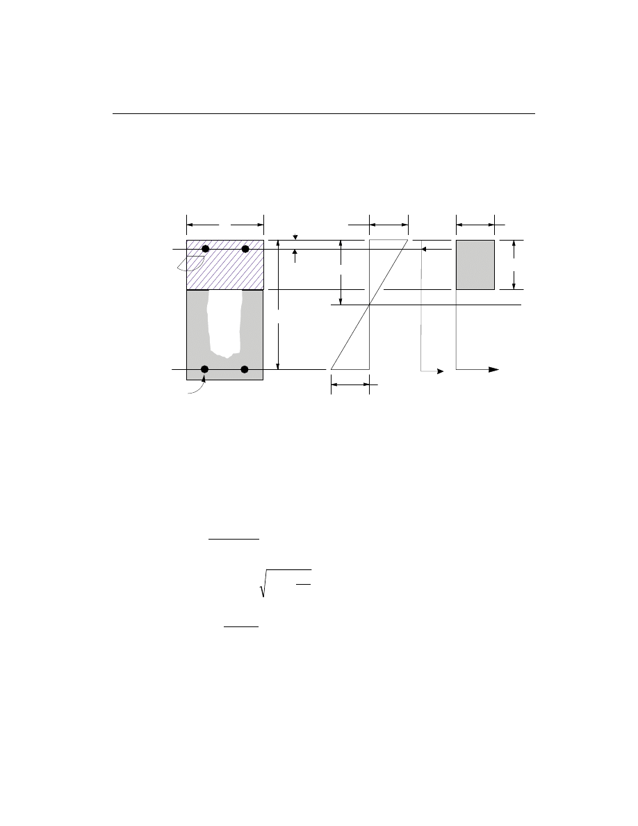
• Calculate the ultimate moment of resistance of the section as singly reinforced.
M
= K f bd
single
cu
¢
2
, where
(BS 3.4.4.4)
K =
¢
0.156 .
• If M
M
single
£
the area of tension reinforcement, A
s
, is obtained from
A =
M
f
z
s
y
(
)
0.87
, where
(BS 3.4.4.4)
z = d
+
-
K
d
0.5
0.25
0.9
0.95
ì
í
î
ü
ý
þ
£
, and
K =
M
f bd
cu
2
.
This is the top steel if the section is under negative moment and the bottom
steel if the section is under positive moment.
Beam Design
113
Chapter VI Design for BS 8110-85 R1989
c
b
d
A
s
(i) BEAM
SECTION
(ii) STRAIN
DIAGRAM
(iii) STRESS
DIAGRAM
ε
s
A'
s
d'
C
s
T
s
T
c
f
s
'
a=0.9x
ε
= 0.0035
0.67f /
cu
m
γ
Figure VI-2
Design of Rectangular Beam Section

• If M
M
single
>
, the area of compression reinforcement, A
s
¢
, is given by
A =
M
M
f
d - d
s
single
s
¢
¢
-
¢
(
)
,
where d
¢ is the depth of the compression steel from the concrete compression
face, and
f =
f
if
d
d
-
f
s
y
y
¢
¢ £ é
ë
0.87
1
2
1
800
ê
ù
û
ú ,
f
-
d
d
if
d
d
>
-
f
s
¢
=
¢
é
ëê
ù
ûú
¢
700 1
2
1
2
1
y
800
é
ë
ê
ù
û
ú .
This is the bottom steel if the section is under negative moment. From equilib-
rium, the area of tension reinforcement is calculated as
A =
M
f
z
+
M
M
f
d - d
s
y
single
y
single
(
)
0.87
(
)
-
¢
, where
(BS 3.4.4.4)
z = d
+
-
K
d
0.5
0.25
0.9
0.776 887
¢
ì
í
î
ü
ý
þ
=
.
Design as a T-Beam
(i)
Flanged beam under negative moment
The contribution of the flange to the strength of the beam is ignored. The design
procedure is therefore identical to the one used for rectangular beams except that in
the corresponding equations b is replaced by b
w
. See Figure VI-3.
(ii)
Flanged beam under positive moment
With the flange in compression, the program analyzes the section by considering
alternative locations of the neutral axis. Initially the neutral axis is assumed to be lo-
cated in the flange. Based on this assumption, the program calculates the exact
depth of the neutral axis. If the stress block does not extend beyond the flange thick-
ness the section is designed as a rectangular beam of width b
f
. If the stress block
extends beyond the flange width, then the contribution of the web to the flexural
strength of the beam is taken into account. See Figure VI-3.
114
Beam Design
SAP2000 Concrete Design Manual

Assuming the neutral axis to lie in the flange, the normalized moment is computed
as
K =
M
f b d
cu
f
2
.
Then the moment arm is computed as
z = d
+
K
d
0.5
0.25
0.9
0.95
-
ì
í
î
ü
ý
þ
£
,
the depth of neutral axis is computed as
x =
d - z
1
0.45
(
) , and
the depth of compression block is given by
a
x
= 0.9 .
• If a
h
f
£
, the subsequent calculations for A
s
are exactly the same as previ-
ously defined for the rectangular section design. However, in this case the
width of the compression flange, b
f
, is taken as the width of the beam, b, for
analysis. Whether compression reinforcement is required depends on whether
K
K
> ¢.
• If a > h
f
, calculation for A
s
is done in two parts. The first part is for balancing
the compressive force from the flange, C
f
, and the second part is for balancing
the compressive force from the web, C
w
, as shown in Figure VI-3.
In this case, the ultimate resistance moment of the flange is given by
M
=
f
b
b
h
d
h
f
cu
f
w
f
f
0.45
(
)
(
0.5
)
-
-
,
the balance of moment taken by the web is computed as
M
= M
M
w
f
-
, and
the normalized moment resisted by the web is given by
K
=
M
f b d
w
w
cu
w
2
.
Beam Design
115
Chapter VI Design for BS 8110-85 R1989
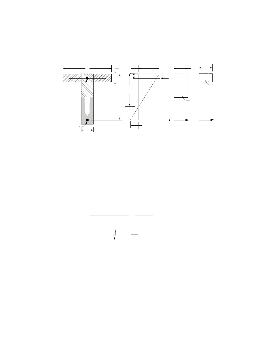
– If K
w
£ 0.156, the beam is designed as a singly reinforced concrete beam.
The area of steel is calculated as the sum of two parts, one to balance compres-
sion in the flange and one to balance compression in the web.
A =
M
f
d
h
+
M
f
z
s
f
y
f
w
y
0.87
0.5
0.87
(
)
-
, where
z = d
+
K
d
w
0.5
0.25
0.9
0.95
-
ì
í
î
ü
ý
þ
£
.
– If K
> K
w
¢, compression reinforcement is required and is calculated as fol-
lows:
The ultimate moment of resistance of the web only is given by
M
= K f b d
uw
cu
w
¢
2
.
The compression reinforcement is required to resist a moment of magnitude
M
M
w
uw
-
. The compression reinforcement is computed as
116
Beam Design
SAP2000 Concrete Design Manual
x
b
f
d
A
s
(i) BEAM
SECTION
(ii) STRAIN
DIAGRAM
(iii) STRESS
DIAGRAM
ε
s
h
f
C
f
T
f
C
w
T
w
b
w
A
s
'
C
s
T
s
d'
f
s
'
ε
= 0.0035
0.67 f /
cu
m
γ
0.67 f /
cu
m
γ
Figure VI-3
Design of a T-Beam Section

A =
M
M
f
d
d
s
w
uw
s
¢
¢
-
- ¢
(
)
,
where, d
¢ is the depth of the compression steel from the concrete compression
face, and
f
f ,
if
d
d
f
s
y
y
¢
=
¢ £
-
é
ë
0.87
1
2
1
800
ê
ù
û
ú , and
f =
d
d
, if
d
d
>
f
s
y
¢
-
¢
é
ëê
ù
ûú
¢
-
700 1
2
1
2
1
800
é
ë
ê
ù
û
ú .
The area of tension reinforcement is obtained from equilibrium
A =
f
M
d
h
M
d
M
M
d
d
s
y
f
f
uw
w
uw
1
0.87
0.5
+
0.777
+
-
-
- ¢
é
ë
ê
ê
ù
û
ú
ú
.
Design Beam Shear Reinforcement
The shear reinforcement is designed for each loading combination in the major and
minor directions of the column. In designing the shear reinforcement for a particu-
lar beam for a particular loading combination due to shear forces in a particular di-
rection, the following steps are involved (BS 3.4.5):
• Calculate the design shear stress as
v =
V
A
, A
bd
cv
cv
=
, where
(BS 3.4.5.2)
v
f
cu
£ 0.8
, and
(BS 3.4.5.2)
v
£ 5 N/mm
2
.
(BS 3.4.5.2)
• Calculate the design concrete shear stress from
v =
k k
A
bd
d
c
m
s
0.79
1
2
100
400
1
3
1
4
g
æ
è
ç
ö
ø
÷ æ
è
ç
ö
ø
÷ ,
(BS 3.4.5.4)
where
,
k
1
is the enhancement factor for support compression, and is conserva-
tively taken as 1,
(BS 3.4.5.8)
Beam Design
117
Chapter VI Design for BS 8110-85 R1989
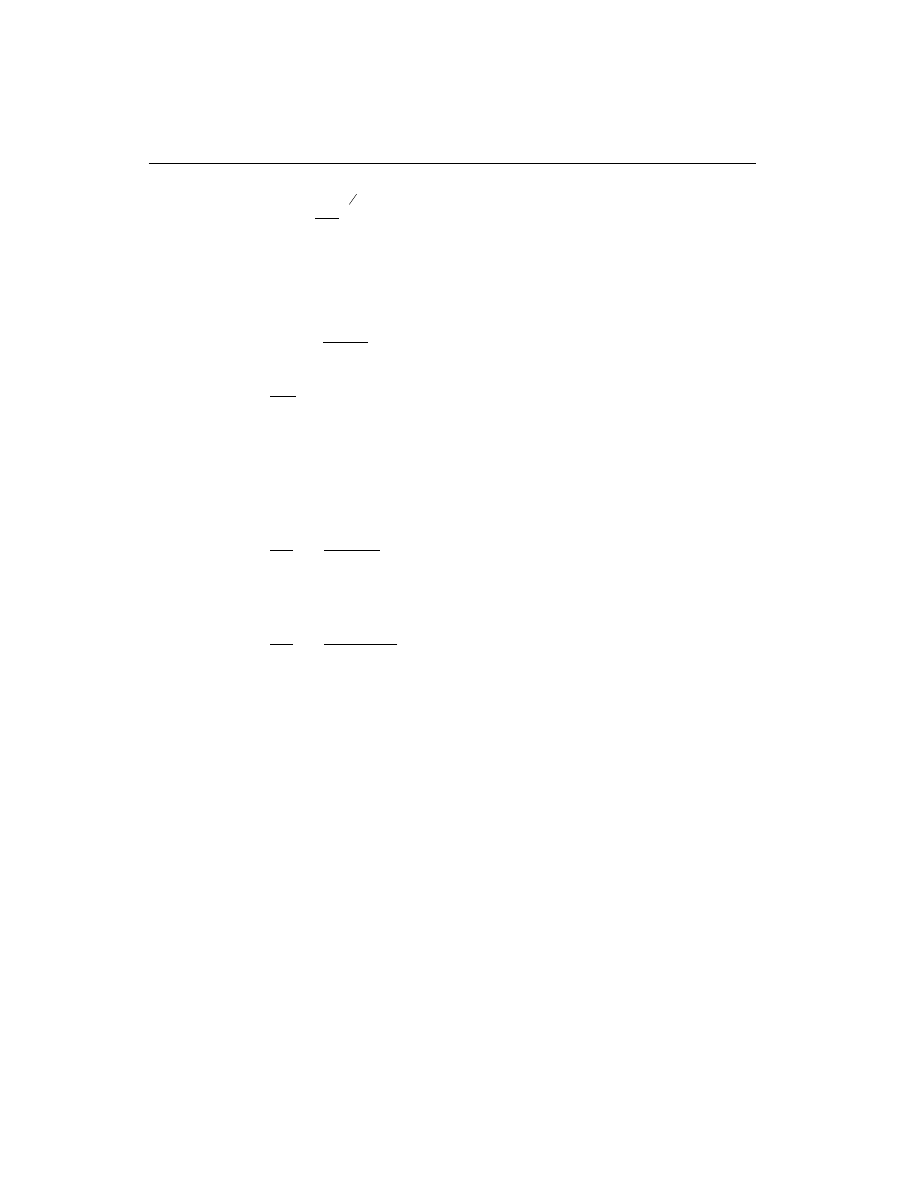
k
f
cu
2
1
3
1
= æ
è
ç
ö
ø
÷ ³
25
, and
(BS 3.4.5.4)
g
m
= 1.25 .
(BS 2.4.4.1)
However, the following limitations also apply:
0.15
£
£
100
3
A
bd
s
,
(BS 3.4.5.4)
400
1
d
³ , and
(BS 3.4.5.4)
f
cu
£ 40 N/mm
2
(for calculation purpose only).
(BS 3.4.5.4)
A
s
is the area of tensile steel.
• If v
v +
c
£
0.4, provide minimum links defined by
A
s
b
f
sv
v
yv
³
0.4
0.87
,
(BS 3.4.5.3)
else if v > v +
c
0.4, provide links given by
A
s
v
v
b
f
sv
v
c
yv
³
-
(
)
0.87
,
(BS 3.4.5.3)
where f
yv
can not be greater than 460 MPA (BS 3.4.5.1).
118
Beam Design
SAP2000 Concrete Design Manual

C h a p t e r VII
Design for Eurocode 2
This chapter describes in detail the various aspects of the concrete design procedure
that is used by SAP2000 when the user selects the 1992 Eurocode 2 (CEN 1992).
Various notations used in this chapter are listed in Table VII-1.
The design is based on user-specified loading combinations. However, the program
provides a set of default load combinations that should satisfy requirements for the
design of most building type structures.
English as well as SI and MKS metric units can be used for input. But the code is
based on Newton-Millimeter-Second units. For simplicity, all equations and de-
scriptions presented in this chapter correspond to Newton-Millimeter-Second
units unless otherwise noted.
Design Load Combinations
The design loading combinations define the various factored combinations of the
load cases for which the structure is to be checked. The design loading combina-
tions are obtained by multiplying the characteristic loads by appropriate partial fac-
tors of safety. If a structure is subjected to dead load (DL) and live load (LL) only,
the design will need only one loading combination, namely 1.35 DL + 1.5 LL.
Design Load Combinations
119
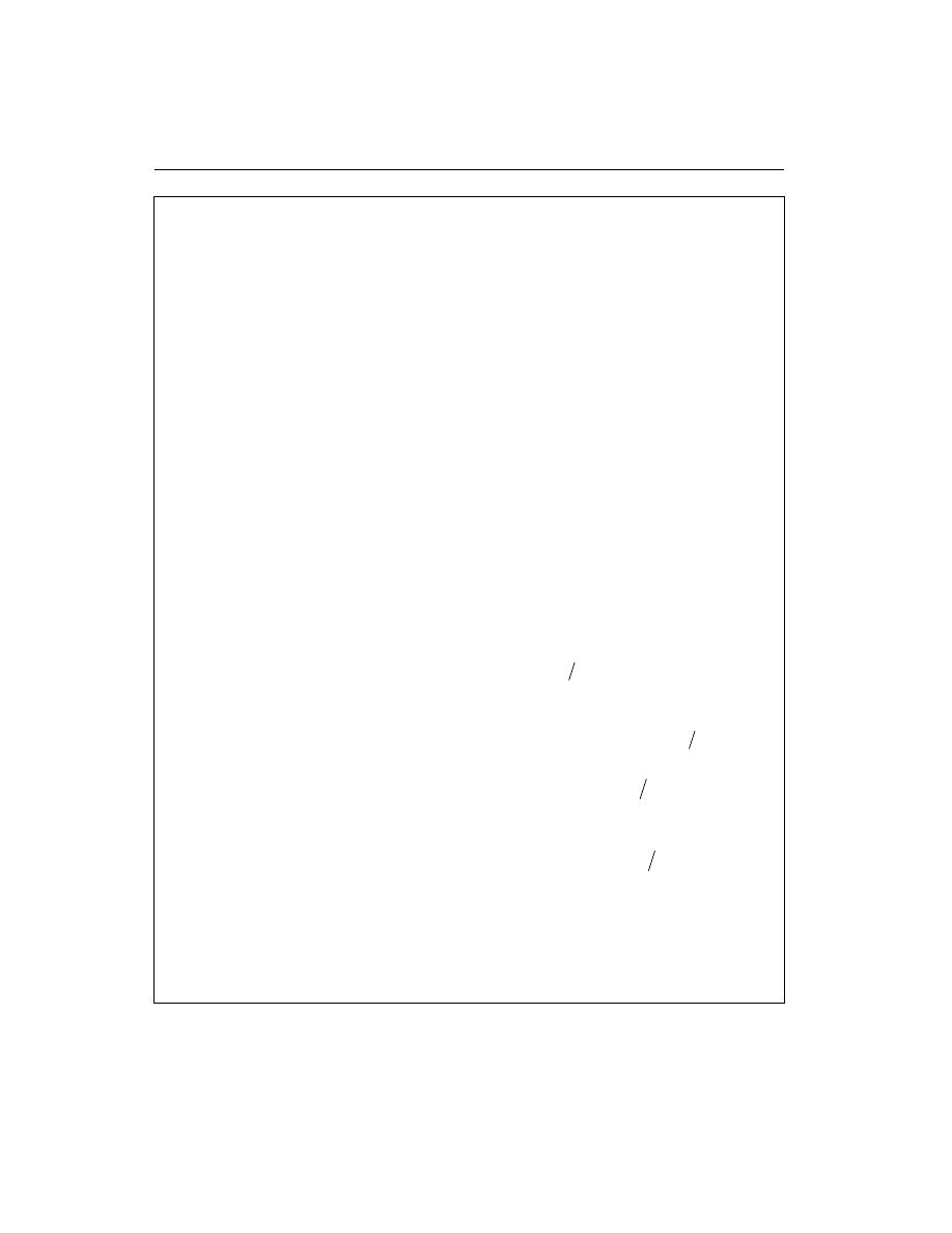
120
Design Load Combinations
SAP2000 Concrete Design Manual
A
c
Gross cross-sectional area of a frame member, mm
2
A
cv
Area of section for shear resistance, mm
2
A
s
Area of tension reinforcement in a beam, mm
2
Area of total longitudinal reinforcement in a column, mm
2
A
s
¢
Area of compression reinforcement, mm
2
A
sw
Total cross-sectional area of links at the neutral axis, mm
2
a
Depth of compression block, mm
b
Width or effective width of the section in the compression zone, mm
b
f
Width or effective width of flange, mm
b
w
Average web width of a flanged beam, mm
d
Effective depth of tension reinforcement, mm
d
¢
Effective depth of compression reinforcement, mm
E
c
Modulus of elasticity of concrete, MPA
E
s
Modulus of elasticity of reinforcement, assumed as 200000 MPa
(EC2 4.2.2.3.2)
e
Eccentricity of axial load in a column, mm
e
min
Minimum or nominal eccentricity, mm
e
tot
Total eccentricity for a braced column, mm
f
cd
Design concrete compressive strength = f
ck
c
g , MPA
f
f
ck
c
,
¢
Characteristic compressive cylinder strength of concrete at 28 days,
MPA
f
cwd
Design concrete compressive strength for shear design = f
cwk
c
g , MPa
f
f
cwk
cs
,
¢
Characteristic compressive cylinder strength for shear design, MPA
f
yd
Design tensile yield strength of reinforcing steel = f
yk
s
g , MPA
f
f
yk
y
,
Characteristic tensile yield strength of reinforcement, MPA
f
s
¢
Stress in a beam compression steel, MPA
f
ywd
Design tensile strength of shear reinforcing steel = f
ywk
s
g , MPA
f
f
ywk
ys
,
Characteristic tensile strength of shear reinforcement, MPA
h
Overall depth of a section in the plane of bending, mm
h
f
Flange thickness, mm
l
0
Effective height of a column, mm
l
col
Clear height between end restraints, mm
Table VII-1
List of Symbols Used in the Eurocode 2
Design Load Combinations
121
Chapter VII Design for Eurocode 2
M
Design moment at a section, N-mm
M
M
1
2
,
Smaller and larger end moments in a slender column, N-mm
M
M
x
y
,
Applied moments about the major and minor axes of a column, N-mm
M
Rd
Design moment of resistance of a section N-mm
M
Sd
Moment at a section obtained from analysis, N-mm
m
Normalized design moment, M bd
f
cd
2
a
N
Ultimate axial load, N
s
v
Spacing of links, mm
V
Rd 1
Design shear resistance from concrete alone, N
V
Rd 2
Design limiting shear resistance of a cross-section, N
V
Sd
Shear force at ultimate design load, N
V V
x
y
,
Shear force at ultimate design load in two directions, N
V
wd
Shear force from reinforcement, N
a
Concrete strength reduction factor for sustained loading
b
Effective length factor,
Enhancement factor of shear resistance for concentrated load
g
f
Partial safety factor for load
g
c
Partial safety factor for concrete strength, 1.5 by default
g
m
Partial safety factor for material strength
g
s
Partial safety factor for steel strength, 1.15 by default
d
Redistribution factor
e
c
Concrete strain
e
s
Strain in tension steel
e
s
¢
Strain in compression steel
n
Effectiveness factor for shear resistance without concrete crushing,
Out of plumbness factor
r
Tension reinforcement ratio, A bd
s
s
cp
Effective average compressive stress in concrete column, MPA
w
Normalized tensile steel ratio, A f
f
bd
s
yd
cd
a
w¢
Normalized compression steel ratio, A f
f
bd
s
yd
cd
¢
a
w
lim
Normalized limiting tensile steel ratio
Table VII-1
List of Symbols Used in the Eurocode 2 (continued)

However, in addition to the dead load and live load, if the structure is subjected to
wind (WL) and earthquake (EL) forces, and considering that wind and earthquake
forces are subject to reversals, the following load combinations might have to be
considered (EC2 2.3.3):
1.35 DL
1.35 DL + 1.50 LL
(EC2 2.3.3)
1.35 DL
± 1.50 WL
1.00 DL
± 1.50 WL
1.35 DL + 1.35 LL
± 1.35 WL
(EC2 2.3.3)
1.00 DL
± 1.00 EL
1.00 DL + 1.5*0.3 LL
± 1.0 EL
(EC2 2.3.3)
These are the default load combinations. These default loading combinations are
produced for persistent and transient design situations (EC2 2.2.1.2) by combining
load due to dead, live, wind, and earthquake loads according to the simplified for-
mula (EC2 2.3.3.1) for ultimate limit states.
In addition to the above load combinations, the code requires that all buildings
should be capable of resisting a notional design ultimate horizontal load applied at
each floor or roof level (EC2 2.5.1.3). It is recommended that the user define addi-
tional load cases for considering the notional load in SAP2000.
Live load reduction factors, as allowed by some design codes, can be applied to the
member forces of the live load condition on a member-by-member basis to reduce
the contribution of the live load to the factored loading.
Design Strength
The design strength for concrete and steel are obtained by dividing the characteris-
tic strength of the materials by a corresponding partial factor of safety as shown be-
low.
f
f
cd
ck
c
=
g ,
(EC2 2.3.3.2)
f
f
cwd
cwk
c
=
g ,
(EC2 2.3.3.2)
f
f
yd
yk
s
=
g ,
(EC2 2.3.3.2)
f
f
ywd
ywk
s
=
g , where
(EC2 2.3.3.2)
122
Design Strength
SAP2000 Concrete Design Manual

g
s
= Partial safety factor for steel = 1.15, and
(EC2 2.3.3.2)
g
c
= Partial safety factor for concrete = 1.5.
(EC2 2.3.3.2)
Column Design
The user may define the geometry of the reinforcing bar configuration of each con-
crete column section. If the area of reinforcing is provided by the user, the program
checks the column capacity. However, if the area of reinforcing is not provided by
the user, the program calculates the amount of reinforcing required for the column.
The design procedure for the reinforced concrete columns of the structure involves
the following steps:
• Generate axial force/biaxial moment interaction surfaces for all of the different
concrete sections types of the model (EC2 4.3.1.2). A typical biaxial interaction
surface is shown in Figure II-1. When the steel is undefined, the program gen-
erates the interaction surfaces for the range of allowable reinforcement. The
minimum reinforcement is taken to be
A
N
f
A
s min
Sd
yd
c
,
max
=
ì
í
ï
îï
0.15
0.003
(EC2 5.4.1.2.1)
and the maximum reinforcement is taken to be 8 percent (EC2 5.4.1.2.1).
• Calculate the capacity ratio or the required reinforcing area for the factored ax-
ial force and biaxial (or uniaxial) bending moments obtained from each loading
combination at each station of the column. The target capacity ratio is taken as
one when calculating the required reinforcing area.
• Design the column shear reinforcing.
The following three sections describe in detail the algorithms associated with the
above-mentioned steps.
Generation of Biaxial Interaction Surfaces
The column capacity interaction volume is numerically described by a series of dis-
crete points that are generated on the three-dimensional interaction failure surface.
In addition to axial compression and biaxial bending, the formulation allows for ax-
ial tension and biaxial bending considerations as shown in Figure II-1. The coordi-
Column Design
123
Chapter VII Design for Eurocode 2
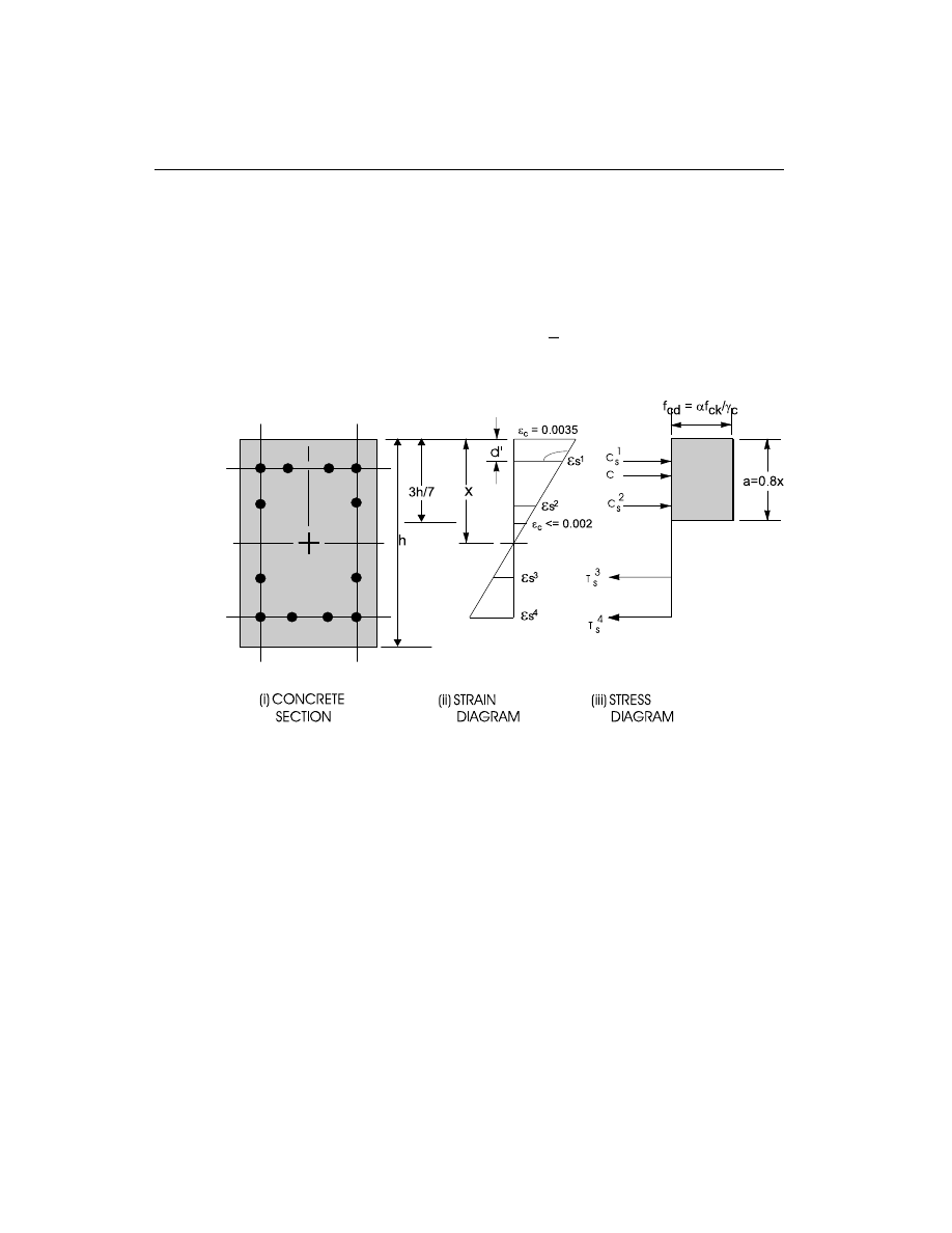
nates of these points are determined by rotating a plane of linear strain in three di-
mensions on the section of the column. See Figure II-2.
The formulation is based consistently upon the basic principles of ultimate strength
design and allows for any doubly symmetric rectangular, square, or circular column
section. The linear strain diagram limits the maximum concrete strain,
e
c
, at the ex-
tremity of the section to 0.0035 and at a depth of
3
7
d from the most compressed face
to 0.0020 (EC2 4.3.1.2). See Figure VII-1.
The stress in the steel is given by the product of the steel strain and the steel modu-
lus of elasticity,
e
s
s
E , and is limited to the design yield strength the steel, f
yd
(EC2
4.2.3.3.3). The area associated with each reinforcing bar is placed at the actual loca-
tion of the center of the bar and the algorithm does not assume any simplifications
in the manner in which the area of steel is distributed over the cross section of the
column (such as an equivalent steel tube or cylinder).
The concrete compression stress block is assumed to be rectangular, with a stress
value of
af
cd
, where f
cd
is the design value of concrete cylinder compressive
strength and
a is the reduction factor to account for sustained compression. a is
generally assumed to be 0.80 (EC2 4.2.1.3). See Figure VII-1. The interaction algo-
124
Column Design
SAP2000 Concrete Design Manual
Figure VII-1
Idealized Stress and Strain Distribution in a Column Section

rithm provides corrections to account for the concrete area that is displaced by the
reinforcement in the compression zone.
Check Column Capacity
The column capacity is checked for each loading combination of each column. In
checking a particular column for a particular loading combination at a particular lo-
cation, the following steps are involved:
• Determine the factored moments and forces from the analysis load cases and
the specified load combination factors to give N, V
x
, V
y
, M
x
, and M
y
.
• Determine the code total moments due to slender column effect. Compute mo-
ments due to minimum eccentricity.
• Check the column capacity ratio or compute the reinforcement for the column
for resisting the factored moments, the code total moments, and the moments
from minimum eccentricity.
The following three subsections describe in detail the algorithms associated with
the above-mentioned steps.
Determine Factored Moments and Forces
Each load combination is defined with a set of load factors corresponding to the
load cases. The factored loads for a particular load combination are obtained by ap-
plying the corresponding load factors to the load cases, giving N, V
x
, V
y
, M
x
, and
M
y
.
Determine Code Total Moments
The determination of code total moments depends on whether the frame is “braced”
or “unbraced” against side-sway.
Braced Column
Eurocode specifies that for braced columns the total moment should be computed
from a set of eccentricities, such that
e
e
e
e
tot
a
=
+
+
0
2
, where
(EC2 4.3.5.6.2)
e
M
N
M
N
M
N
M
M
0
1
2
2
1
2
=
+
³
£
0.4
0.6
0.4
where
,
, (EC2 4.3.5.6.2)
Column Design
125
Chapter VII Design for Eurocode 2

e
l
a
=
n
0
2
,
(EC2 4.3.5.4)
n is taken as 1/100, however the user can override this value (EC2 2.5.1.3),
l
0
is the effective length of a column in a given plane and is obtained from
l
l
col
0
=
b
,
(EC2 4.3.5.3.5)
where
b is the effective length factor depending on the end conditions and
resistance against side-sway,
b is conservatively taken as 1 for braced
frames, and l
col
is the unsupported length corresponding to instability in
the major or minor direction of the element, l
l
x
y
and
in Figure II-4.
e
k k l f
E d
yd
s
2
1
2 0
2
=
4.5
,
(EC2 4.3.5.6.3)
k
1
0
15
20
15
35
1
35
=
£
-
< £
>
ì
í
ï
î
ï
for
,
, for
,
for
,
l
l
l
l
0.75
l b
= l r
G
0
,
r
G
= the radius of gyration about the axis of bending, and
k
N
N
N
N
ud
sd
ud
bal
2
1
=
-
-
£ , k
2
is taken as 1.0.
However, the minimum eccentricity requirement is satisfied such that
M
N
Rd
Sd
>
e
min
, where
(EC2 4.3.5.5.3)
M
Rd
= Design moment resistance of the section,
N
Sd
= The axial force obtained from analysis, and
e
min
is the minimum eccentricity which is taken as 0.05 times the overall di-
mension of the column in the plane of bending and is given by
e
h
min
= 20 .
(EC2 4.3.5.5.3)
Finally the design moments are computed from the maximum of the three,
M
N
e
N
e
M
Rd
Rd
tot
Rd
factored
= max(
)
,
,
min
.
(EC2 4.3.5.6)
126
Column Design
SAP2000 Concrete Design Manual

In biaxial bending, the program calculates the design moments at any station about
two axes.
Unbraced Column
In the case of the unbraced column, it is assumed that the SAP2000 analysis in-
cludes P-
D effects so that the analysis results include the effects of the additional
moments. Therefore, any additional computation is not required. That means, the
moment magnification factors for moments causing sidesway are taken as unity.
However, it is recommended that a factor be used to obtain a axial force P equiva-
lent to 1.35 DL + 1.35 LL for P-
D analysis (White and Hajjar 1991).
In addition, the minimum eccentricity requirement needs to be satisfied so that the
design moment should at least be
M
Rd
³ N e
min
,
(EC2 4.3.5.5.3)
where, e
min
is the minimum eccentricity which is described in the previous section.
In biaxial bending the algorithm ensures that the eccentricity exceeds the minimum
about both the axes simultaneously.
Determine Capacity Ratio
As a measure of the stress condition of the column, a capacity ratio is calculated.
The capacity ratio is basically a factor that gives an indication of the stress condi-
tion of the column with respect to the capacity of the column.
Before entering the interaction diagram to check the column capacity, the design
forces N M
M
x
y
,
and
,
are obtained according to the previous subsections. The
point (N M M
x
y
,
,
) is then placed in the interaction space shown as point L in Figure
II-3. If the point lies within the interaction volume, the column capacity is ade-
quate; however, if the point lies outside the interaction volume, the column is over-
stressed.
This capacity ratio is achieved by plotting the point L and determining the location
of point C. The point C is defined as the point where the line OL (if extended out-
wards) will intersect the failure surface. This point is determined by three-
dimensional linear interpolation between the points that define the failure surface.
See Figure II-3. The capacity ratio, CR, is given by the ratio
OL
OC
.
• If OL = OC (or CR=1) the point lies on the interaction surface and the column is
stressed to capacity.
Column Design
127
Chapter VII Design for Eurocode 2

• If OL < OC (or CR<1) the point lies within the interaction volume and the col-
umn capacity is adequate.
• If OL > OC (or CR>1) the point lies outside the interaction volume and the col-
umn is overstressed.
The maximum of all the values of CR calculated from each load combination is re-
ported for each check station of the column along with the controlling
N M
M
x
y
,
, and
set and associated load combination number.
If the reinforcing area is not defined, SAP2000 computes the reinforcement that
will give an interaction ratio of unity.
Design Column Shear Reinforcement
The shear reinforcement is designed for each loading combination in the major and
minor directions of the column. The assumptions in designing the shear reinforce-
ment are as follows:
• The column sections are assumed to be prismatic. The effect of any variation of
width in the column section on the concrete shear capacity is neglected.
• The effect on the concrete shear capacity of any concentrated or distributed
load in the span of the column between two beams is ignored. Also, the effect of
the direct support on the columns provided by the beams is ignored.
• All shear reinforcement is provided through shear reinforcements which are
perpendicular to the longitudinal reinforcement.
• The effect of any torsion is neglected for the design of shear reinforcement.
In designing the shear reinforcement for a particular column for a particular loading
combination due to shear forces in a particular direction, the following steps of the
standard method are involved (EC2 4.3.2.1):
• Obtain the design value of the applied shear forceV
Sd
from the SAP2000 analy-
sis results.
V
V
V
Sd
=
2
3
or
• Calculate the design shear resistance of the member without shear reinforce-
ment.
V
k
A
Rd
Rd
cp
cv
1
1
=
+
+
b t
r
s
(
)
1.2
40
0.15
, where
(EC2 4.3.2.3(1))
128
Column Design
SAP2000 Concrete Design Manual

b = enhancement factor for shear resistance for members with
concentrated loads located near the face of the support.
b is taken as 1.
(EC2 4.3.2.1(9))
t
Rd
=
0.25
0.05
f
ctk
c
g
, basic design shear strength of concrete, (EC2 4.3.2.3)
f
f
ctk
ctm
0 05
.
= 0.7
,
(EC2 3.1.2.3)
f
f
ctm
cwk
= 0.3
2
3
,
(EC2 3.1.2.3)
k
= strength magnification factor for curtailment of
longitudinal reinforcement and depth of the section,
and is considered to be 1,
(EC2 4.3.2.3)
r
1
= tension reinforcement ratio =
A
A
s
cv
1
£ 0.02 ,
(EC2 4.3.2.3)
A
s1
= area of tension reinforcement, taken as half of total
longitudinal reinforcement, A
s
2, in a column,
(EC2 4.3.2.3)
s
cp
= average stress in concrete due to axial force =
N
A
Sd
c
, (EC2 4.3.2.3)
N
Sd
= the design value of the applied axial force in section,
N
Sd
is taken as positive for compression and
negative for tension, and
(EC2 4.3.2.3)
A
c
= the total gross area of concrete cross-section,
(EC2 4.3.2.3)
A
cv
= the total area of concrete cross-section, it is taken
as A
cv
which is shown in Figure VII-2. For a rectangular
section A
cv
equals b d
w
.
• Calculate the maximum design shear force that can be carried without crushing
of the notional concrete compressive struts, V
Rd
red
2 ,
.
V
V
f
Rd
red
Rd
cp eff
cd
2
2
1
,
,
=
-
æ
è
çç
ö
ø
÷÷
1.67
s
, where
(EC2 4.3.2.2(4))
0
2
2
£
£
V
V
Rd
red
Rd
,
,
(EC2 4.3.2.2(4))
V
f
A
Rd
cwd
cv
2
1
2
= n
0.9
,
(EC2 4.3.2.3(3))
Column Design
129
Chapter VII Design for Eurocode 2
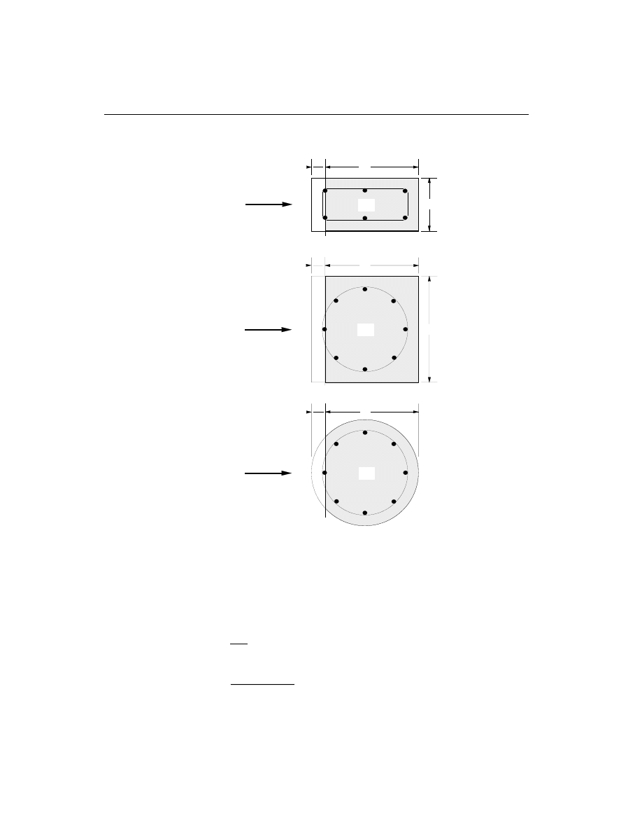
n = 0.7
200
0.5
-
³
f
ck
, the effectiveness factor,
(EC2 4.3.2.3)
s
cp eff
Sd
yd
s
c
N
f
A
A
,
=
-
2
, effective average stress in concrete, (EC2 4.3.2.2)
130
Column Design
SAP2000 Concrete Design Manual
SQUARE WITH CIRCULAR REBAR
DIRECTION
OF SHEAR
FORCE
DIRECTION
OF SHEAR
FORCE
DIRECTION
OF SHEAR
FORCE
d
b
d'
RECTANGULAR
Acv
d'
d
b
Acv
d'
CIRCULAR
d
Acv
Figure VII-2
Shear Stress Area, A
cv
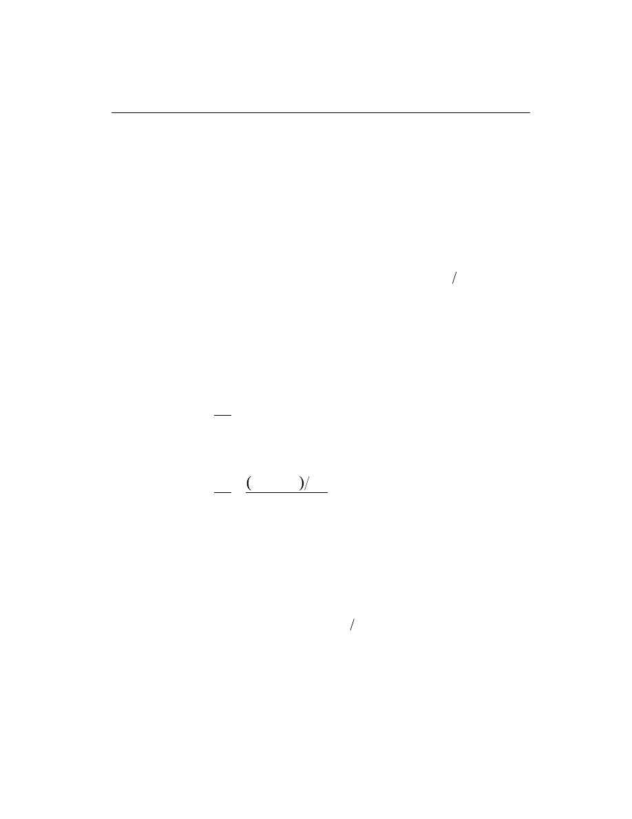
N
Sd
= the design axial force, it is taken positive for compression
and negative for tension,
(EC2 4.3.2.2(4))
f
yd
= the design yield stress of compression steel,
(EC2 4.3.2.2(4))
f
yd
£ 400 MPa,
(EC2 4.3.2.2(4))
A
s 2
is the area of reinforcement in the compression zone, A
s 2
is
taken as half of total longitudinal reinforcement, A
s
2,
in a column, and
(EC2 4.3.2.2(4))
A
c
is the gross total area of concrete cross-section.
• The shear reinforcement per unit spacing is computed following the Standard
method as follows (EC2 4.3.2.4.3):
If V
V
Sd
Rd
£
1
,
A
s
sw
= 0 ,
(EC2 4.3.2.4.3)
else if V
V
V
Rd
Sd
Rd
red
1
2
<
<
.
,
A
s
V
V
A
f
b
sw
Sd
Rd
cv
ywd
w
=
-
1
0.9
, where
(EC2 4.3.2.4.3)
f
ywd
is the design yield strength of the shear reinforcement.
else if V
V
Sd
Rd
red
³
2.
,
a failure condition is declared.
(EC2 4.3.2.2(4))
The maximum of all the calculated A
s
sw
values, obtained from each load com-
bination, is reported for the major and minor directions of the column along
with the controlling shear force and associated load combination number.
Column Design
131
Chapter VII Design for Eurocode 2
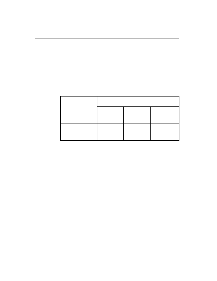
• For all columns and at any station, the minimum area of shear reinforcement is
imposed as follows:
A
s
b
sw
w
w
³ r
(EC2 5.4.2.2(5))
In the above equation
r
w
is the shear reinforcement ratio. It is taken based on
the concrete compression strength for shear use f
cs
¢
which is the same as f
cwk
and the shear rebar yield strength f
ys
which is the same as f
ywk
.
r
w
is deter-
mined from the following table (EC2 Table 5.5).
Beam Design
In the design of concrete beams, SAP2000 calculates and reports the required areas
of steel for flexure and shear based upon the beam moments, shears, load combina-
tion factors, and other criteria described below. The reinforcement requirements
are calculated at a user defined number of check stations along the beam span.
All the beams are only designed for major direction flexure and shear. Effects
due to any axial forces, minor direction bending, and torsion that may exist in
the beams must be investigated independently by the user.
The beam design procedure involves the following steps:
• Design beam flexural reinforcement
• Design beam shear reinforcement
132
Beam Design
SAP2000 Concrete Design Manual
Concrete Strength
(MPA)
Steel Strength (MPA)
f
ywk
£ 220
220
400
<
£
f
ywk
f
ywk
> 400
f
cwk
£ 20
0.0016
0.0009
0.0007
20
<
£
f
cwk
35
0.0024
0.0013
0.0011
f
cwk
> 35
0.0030
0.0016
0.0013
Table VII.2
Minimum shear reenforcement ratio,
r
w

Design Beam Flexural Reinforcement
The beam top and bottom flexural steel is designed at the design stations along the
beam span. In designing the flexural reinforcement for a particular beam for a par-
ticular section, for the beam major moment, the following steps are involved:
• Determine the maximum factored moments
• Determine the reinforcing steel
Determine Factored Moments
In the design of flexural reinforcement, the factored moments for each load combi-
nation at a particular beam station are obtained by factoring the corresponding mo-
ments for different load cases with the corresponding load factors. The beam sec-
tion is then designed for the maximum positive M
u
+
and maximum negative M
u
-
factored moments obtained from all of the load combinations
.
Negative beam moments produce top steel. In such cases the beam is always de-
signed as a rectangular section. Positive beam moments produce bottom steel. In
such cases, the beam may be designed as a rectangular section, or T-Beam effects
may be included.
Determine Required Flexural Reinforcement
In the flexural reinforcement design process, the program calculates both the ten-
sion and compression reinforcement. Compression reinforcement is added when
the applied design moment exceeds the maximum moment capacity of a singly re-
inforced section. The user has the option of avoiding the compression reinforce-
ment by increasing the effective depth, the width, or the grade of concrete.
The design procedure is based on the simplified rectangular stress block as shown
in Figure VII-3 (EC2 4.3.1.2). Furthermore, it is assumed that moment redistribu-
tion in the member does not exceed the code specified limiting value. The code also
places a limitation on the neutral axis depth, to safeguard against non-ductile fail-
ures (EC2 2.5.3.4.2). When the applied moment exceeds M
u
, the area of compres-
sion reinforcement is calculated on the assumption that the neutral axis depth re-
mains at the maximum permitted value.
The design procedure used by SAP2000, for both rectangular and flanged sections
(L- and T-beams) is summarized below. It is assumed that the design ultimate axial
force does not exceed 0.08 f
A
ck
g
(EC2 4.3.1.2), hence all the beams are designed
for major direction flexure and shear only.
Beam Design
133
Chapter VII Design for Eurocode 2

Design as a Rectangular Beam
For rectangular beams, the normalized moment, m, and the normalized section ca-
pacity as a singly reinforced beam, m
lim
, are obtained first. The reinforcing steel
area is determined based on whether m is greater than, less than, or equal to m
lim
.
• Calculate the normalized design moment, m.
m
M
bd
f
cd
=
2
a
, where
a is the reduction factor to account for sustained compression. a is generally
assumed to be 0.80 for assumed rectangular stress block, (EC2 4.2.1.3). See
also page 124 for
a . The concrete compression stress block is assumed to be
rectangular, with a stress value of
af
cd
, where f
cd
is the design concrete
strength and is equal to
f
ck
c
g
. See Figure VII-3.
• Calculate the normalized concrete moment capacity as a singly reinforced
beam, m
lim
.
m
x
d
x
d
lim
lim
lim
= æ
è
ç
ö
ø
÷
-
æ
è
ç
ö
ø
÷
é
ëê
ù
ûú
1 0.4
,
where the limiting value of the ratio,
x
d
, of the neutral axis depth at the ultimate
limit state after redistribution to the effective depth, is expressed as a function
of the ratio of the redistributed moment to the moment before redistribution,
d,
as follows:
x
d
f
ck
æ
è
ç
ö
ø
÷ =
-
£
lim
d 0.44
1.25
if
35
,
,
(EC2 2.5.3.4.1)
x
d
f
ck
æ
è
ç
ö
ø
÷ =
-
>
lim
d 0.56
1.25
if
35
,
,
(EC2 2.5.3.4.1)
d is assumed to be 1.
134
Beam Design
SAP2000 Concrete Design Manual
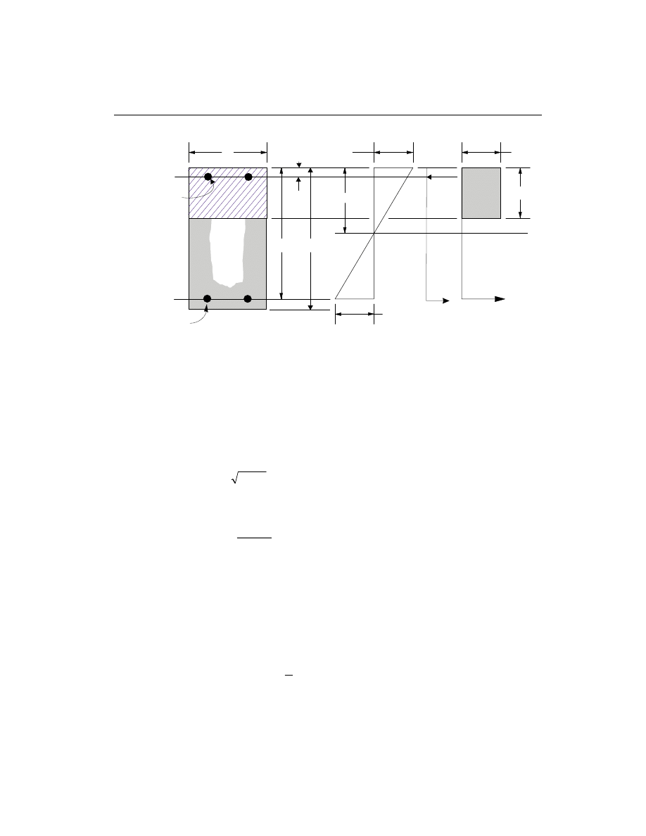
• If m
m
£
lim
, a singly reinforced beam will suffice. Calculate the normalized
steel ratio,
w= -
-
1
1 2m .
Calculate the area of tension reinforcement, A
s
, from
A
f
bd
f
s
cd
yd
=
w
a
é
ë
ê
ê
ù
û
ú
ú
.
This is the top steel if the section is under negative moment and the bottom
steel if the section is under positive moment.
• If m > m
lim
, the beam will not suffice as a singly reinforced beam. Both top and
bottom steel are required.
– Calculate the normalized steel ratios
w¢, w
lim
, and
w.
w
lim
lim
=
æ
è
ç
ö
ø
÷
0.807
x
d
,
Beam Design
135
Chapter VII Design for Eurocode 2
x
b
d
h
A
s
(i) BEAM
SECTION
(ii) STRAIN
DIAGRAM
(iii) STRESS
DIAGRAM
ε
s
A'
s
d'
Cs
T
s
T
c
f
s
'
a=0.8x
ε
= 0.0035
α γ
f /
ck
c
Figure VII-3
Design of a Rectangular Beam

w¢ =
-
- ¢
m
m
d d
lim
1
/
, and
w w
w
=
+ ¢
lim
.
– Calculate the area of compression and tension reinforcement, A
s
¢ and A
s
, as
follows:
A =
f
bd
f
s
cd
s
¢
¢
¢ é
ë
ê
ù
û
ú
w
a
, and
A
f
bd
f
s
cd
yd
=
w
a
é
ë
ê
ê
ù
û
ú
ú
where
f
E
d
d
f
s
s
c max
y
s
¢
=
-
¢
é
ëê
ù
ûú
£
e
g
,
1
2
.
Design as a T-Beam
(i) Flanged beam under negative moment
The contribution of the flange to the strength of the beam is ignored if the flange is
in the tension side. See Figure VII-4. The design procedure is therefore identical to
the one used for rectangular beams. However, the width of the web, b
w
, is taken as
the width of the beam.
(ii) Flanged beam under positive moment
With the flange in compression, the program analyzes the section by considering
alternative locations of the neutral axis. Initially the neutral axis is assumed to be lo-
cated within the flange. Based on this assumption, the program calculates the depth
of the neutral axis. If the stress block does not extend beyond the flange thickness
the section is designed as a rectangular beam of width b
f
. If the stress block extends
beyond the flange, additional calculation is required. See Figure VII-4.
• Calculate the normalized design moment, m.
m
M
b d
f
f
cd
=
2
a
, where
a is the reduction factor to account for sustained compression. a is generally
assumed to be 0.80 for assumed rectangular stress block, (EC2 4.2.1.3). See
136
Beam Design
SAP2000 Concrete Design Manual
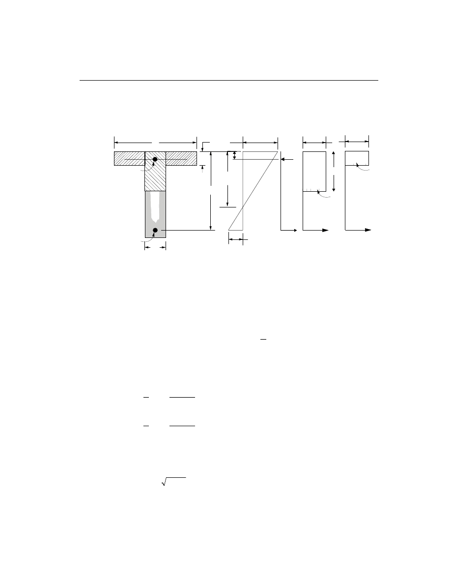
also page 124 for
a. The concrete compression stress block is assumed to be
rectangular, with a stress value of
af
cd
.
• Calculate the limiting value of the ratio,
x
d
æ
è
ç
ö
ø
÷
lim
, of the neutral axis depth at the
ultimate limit state after redistribution to the effective depth, which is ex-
pressed as a function of the ratio of the redistributed moment to the moment be-
fore redistribution,
d, as follows:
x
d
f
ck
æ
è
ç
ö
ø
÷ =
-
£
lim
d 0.44
1.25
if
35
,
,
(EC2 2.5.3.4.1)
x
d
f
ck
æ
è
ç
ö
ø
÷ =
-
>
lim
d 0.56
1.25
if
35
,
,
(EC2 2.5.3.4.1)
d is assumed to be 1.
• Calculate the normalized steel ratio,
w= -
-
1
1 2m .
Beam Design
137
Chapter VII Design for Eurocode 2
x
d
A
s
(i) BEAM
SECTION
(ii) STRAIN
DIAGRAM
(iii) STRESS
DIAGRAM
ε
s
h
f
C
f
T
f
C
w
T
w
b
w
b
f
A
s
'
C
s
T
s
d'
f
s
'
ε
= 0.0035
α
γ
f /
ck
c
α
γ
f /
ck
c
a = 0.8x
Figure VII-4
Design of a T-Beam Section
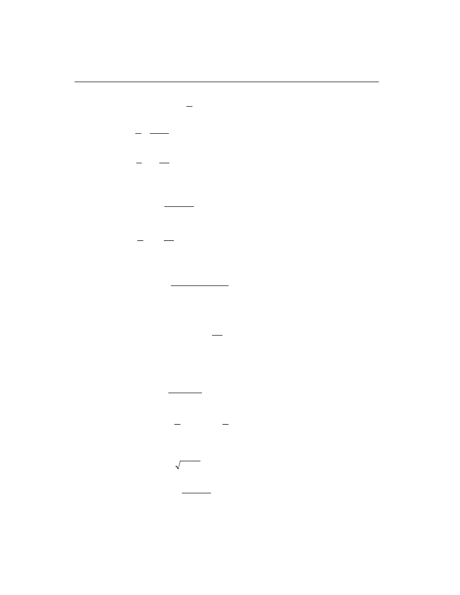
• Calculate the ratio,
x
d
, as follows:
x
d
= w
0.807
.
• If
x
d
h
d
f
æ
è
ç
ö
ø
÷ £
æ
è
çç
ö
ø
÷÷ , the neutral axis lies within the flange. Calculate the area of
tension reinforcement, A
s
, as follows:
A =
f
b d
f
s
cd
f
yd
w
a
é
ë
ê
ê
ù
û
ú
ú
.
• If
x
d
h
d
f
æ
è
ç
ö
ø
÷ >
æ
è
çç
ö
ø
÷÷ , the neutral axis lies below the flange.
Calculate steel area required for equilibrating the flange compression, A
s 2
.
A
b
b
h
f
f
s
f
w
f
cd
yd
2
=
(
)
-
a
,
and the corresponding resistive moment is given by
M
A f
d
h
s
yd
f
2
2
2
=
-
æ
è
çç
ö
ø
÷÷ .
Calculate steel area required for rectangular section of width b
r
to resist
moment, M
M
M
1
2
=
-
, as follows:
m
M
b d
f
w
cd
1
1
2
=
a
, and
m
x
d
x
d
lim
lim
lim
= æ
è
ç
ö
ø
÷
-
æ
è
ç
ö
ø
÷
é
ëê
ù
ûú
1 0.4
,
– If m
m
1
£
lim
,
w
1
1
1
1 2
= -
- m , and
A
f
b d
f
s
cd
w
yd
1
1
=
w
a
é
ë
ê
ê
ù
û
ú
ú
.
138
Beam Design
SAP2000 Concrete Design Manual

– If m > m
1
lim
,
w¢ =
-
- ¢
m
m
d d
1
1
lim
/
,
w
lim
lim
=
æ
è
ç
ö
ø
÷
0.807
x
d
,
w
w
w
1
=
+ ¢
lim
,
A =
f
bd
f
s
cd
s
¢
¢
¢ é
ë
ê
ù
û
ú
w
a
, and
A
f
b d
f
s
cd
w
yd
1
1
=
w
a
é
ë
ê
ê
ù
û
ú
ú
where
f
E
d
d
f
s
s
c max
y
s
¢
=
-
¢
é
ëê
ù
ûú
£
e
g
,
1
2
.
– Calculate total steel area required for the tension side.
A
A
A
s
s
s
=
+
1
2
Design Beam Shear Reinforcement
The shear reinforcement is designed for each loading combination at various check
stations along the beam span. The assumptions in designing the shear reinforce-
ments are as follows:
• The beam sections are assumed to be prismatic. The effect of any variation of
width in the beam section on the concrete shear capacity is neglected.
• The effect on the concrete shear capacity of any concentrated or distributed
load in the span of the beam between two columns is ignored. Also, the effect of
the direct support on the beams provided by the columns is ignored.
• All shear reinforcements are assumed to be perpendicular to the longitudinal
reinforcement.
• The effect of any torsion is neglected for the design of shear reinforcement.
In designing the shear reinforcement for a particular beam for a particular loading
combination due to shear forces in a particular direction, the following steps of the
standard method are involved (EC2 4.3.2.1).
Beam Design
139
Chapter VII Design for Eurocode 2

• Obtain the design value of the applied shear force V
Sd
from the SAP2000
analysis results.
V
V
Sd
=
2
• Calculate the design shear resistance of the member without shear reinforce-
ment.
V
k
b d
Rd
Rd
cp
w
1
1
=
+
+
b t
r
s
(
)
1.2
40
0.15
, where
(EC2 4.3.2.3(1))
b = enhancement factor for shear resistance for members with
concentrated loads located near the face of the support.
b is taken as 1.
(EC2 4.3.2.1(9))
t
Rd
=
0.25
0.05
f
ctk
c
g
, basic design shear strength of concrete, (EC2 4.3.2.3)
f
f
ctk
ctm
0 05
.
= 0.7
,
(EC2 3.1.2.3)
f
f
ctm
cwk
= 0.3
2
3
,
(EC2 3.1.2.3)
k
= strength magnification factor for curtailment of
longitudinal reinforcement and depth of the section,
and is considered to be 1,
(EC2 4.3.2.3)
r
1
= tension reinforcement ratio =
A
b d
s
w
1
£ 0.02 ,
(EC2 4.3.2.3)
A
s1
= area of tension reinforcement in the beam,
(EC2 4.3.2.3)
s
cp
= average stress in concrete due to axial force =
N
A
Sd
c
, (EC2 4.3.2.3)
N
Sd
= the design value of the applied axial force in section,
N
Sd
is taken as positive for compression and
negative for tension, and
(EC2 4.3.2.3)
A
c
= the total gross area of concrete cross-section,
(EC2 4.3.2.3)
• Calculate the maximum design shear force that can be carried without crushing
of the notional concrete compressive struts, V
Rd
red
2 ,
.
V
V
f
Rd
red
Rd
cp eff
cd
2
2
1
,
,
=
-
æ
è
çç
ö
ø
÷÷
1.67
s
, where
(EC2 4.3.2.2(4))
140
Beam Design
SAP2000 Concrete Design Manual
0
2
2
£
£
V
V
Rd
red
Rd
,
,
(EC2 4.3.2.2(4))
V
f
A
Rd
cwd
cv
2
1
2
= n
0.9
,
(EC2 4.3.2.3(3))
n = 0.7
200
0.5
-
³
f
ck
, the effectiveness factor,
(EC2 4.3.2.3)
s
cp eff
Sd
yd
s
c
N
f
A
A
,
=
-
2
, effective average stress in concrete, (EC2 4.3.2.2)
N
Sd
= the design axial force, it is taken positive for compression
and negative for tension,
(EC2 4.3.2.2(4))
f
yd
= the design yield stress of compression steel,
(EC2 4.3.2.2(4))
f
yd
£ 400 MPa,
(EC2 4.3.2.2(4))
A
s 2
is the area of the compression reinforcement, and
(EC2 4.3.2.2(4))
A
c
is the gross total area of concrete cross-section.
• The shear reinforcement per unit spacing is computed following the Standard
method as follows (EC2 4.3.2.4.3):
If V
V
Sd
Rd
£
1
,
A
s
sw
= 0 ,
(EC2 4.3.2.4.3)
else if V
V
V
Rd
Sd
Rd
red
1
2
<
<
.
,
A
s
V
V
A
f
b
sw
Sd
Rd
cv
ywd
w
=
-
1
0.9
, where
(EC2 4.3.2.4.3)
f
ywd
is the design yield strength of the shear reinforcement.
else if V
V
Sd
Rd
red
³
2.
,
a failure condition is declared.
(EC2 4.3.2.2(4))
The maximum of all the calculated A
s
sw
values, obtained from each load com-
bination, is reported for the major directions of the beam along with the control-
ling shear force and associated load combination number.
Beam Design
141
Chapter VII Design for Eurocode 2

• For all beams and at any station, the minimum area of shear reinforcement is
imposed as follows:
A
s
b
sw
w
w
³ r
(EC2 5.4.2.2(5))
In the above equation
r
w
is the shear reinforcement ratio. It is taken based on
the concrete compression strength for shear use f
cs
¢
which is the same as f
cwk
and the shear rebar yield strength f
ys
which is the same as f
ywk
.
r
w
is deter-
mined from Table VII.2 according to the EC2 Table 5.5.
142
Beam Design
SAP2000 Concrete Design Manual

C h a p t e r VIII
Design for NZS 3101-95
This chapter describes in detail the various aspects of the concrete design procedure
that is used by SAP2000 when the user selects the New Zealand code, NZS 3101-
95 (NZS 1995). Various notations used in this chapter are listed in Table VIII-1.
The design is based on user-specified loading combinations. But the program pro-
vides a set of default load combinations that should satisfy requirements for the de-
sign of most building type structures.
SAP2000 provides options to design or check all types of moment resisting frames
as required for regular and seismic design. For regular design, the frame should be
identified as Ordinary. For Seismic design, the frame has to be identified as either
Ductile, Limited, or Elastic to represent Ductile moment resisting frames, frames
with Limited ductility, and Elastically responding frames, respectively. The details
of the design criteria used for the different framing systems are described in the fol-
lowing sections.
English as well as SI and MKS metric units can be used for input. But the code is
based on Newton-Millimeter-Second units. For simplicity, all equations and de-
scriptions presented in this chapter correspond to Newton-Millimeter-Second
units unless otherwise noted.
143

144
SAP2000 Concrete Design Manual
A
cv
Area of concrete used to determine shear stress, sq-mm
A
g
Gross area of concrete, sq-mm
A
s
Area of tension reinforcement, sq-mm
A
s
¢
Area of compression reinforcement, sq-mm
A
s required
(
)
Area of steel required for tension reinforcement, sq-mm
A
st
Total area of column longitudinal reinforcement, sq-mm
A
v
Area of shear reinforcement, sq-mm
a
Depth of compression block, mm
a
b
Depth of compression block at balanced condition, mm
a
max
Maximum depth of compression block, mm
b
Width of member, mm
b
f
Effective width of flange (T-Beam section), mm
b
w
Width of web (T-Beam section), mm
C
m
Coefficient, dependent upon column curvature, used to
calculate moment magnification factor
c
Depth to neutral axis, mm
c
b
Depth to neutral axis at balanced conditions, mm
d
Distance from compression face to tension reinforcement, mm
d
¢
Concrete cover to center of reinforcing, mm
d
s
Thickness of slab (T-Beam section), mm
E
c
Modulus of elasticity of concrete, MPA
E
s
Modulus of elasticity of reinforcement, assumed as 200,000 MPa
(NZS 3.8.3.3)
f
c
¢
Specified compressive strength of concrete, MPA
f
y
Specified yield strength of flexural reinforcement, MPA
f
yt
Specified yield strength of shear reinforcement, MPA
h
Dimension of beam or column, mm
I
g
Moment of inertia of gross concrete section about centroidal axis,
neglecting reinforcement, mm
4
k
Effective length factor
L
Clear unsupported length, mm
Table VIII-1
List of Symbols Used in the New Zealand code

145
Chapter VIII Design for NZS 3101-95
M
1
Smaller factored end moment in a column, N-mm
M
2
Larger factored end moment in a column, N-mm
M
c
Factored moment to be used in design, N-mm
M
ns
Nonsway component of factored end moment, N-mm
M
s
Sway component of factored end moment, N-mm
M
*
Factored moment at section, N-mm
M
x
*
Factored moment at section about X-axis, N-mm
M
y
*
Factored moment at section about Y-axis, N-mm
N
b
Axial load capacity at balanced strain conditions, N
N
c
Critical buckling strength of column, N
N
max
Maximum axial load strength allowed, N
N
0
Axial load capacity at zero eccentricity, N
N
*
Factored axial load at section, N
v
b
Basic shear stress resisted by concrete, MPA
v
c
Shear stress resisted by concrete, MPA
V
c
Shear force resisted by concrete, N
V
D
L
+
Shear force from span loading, N
V
p
Shear force computed from probable moment capacity, N
V
*
Factored shear force at a section, N
V
s
Shear force at a section resisted by steel, N
a
Reinforcing steel overstrength factor
a
1
Average stress factor in equivalent stress block
b
1
Factor for obtaining depth of compression block in concrete
b
d
Absolute value of the ratio of the maximum factored axial
dead load moment to the maximum factored total load moment
d
b
Moment magnification factor for nonsway moments
d
s
Moment magnification factor for sway moments
e
c
Strain in concrete
e
s
Strain in reinforcing steel
j
b
Strength reduction factor for bending
Table VIII-1
List of Symbols Used in the New Zealand code (continued)

Design Load Combinations
The design load combinations are the various combinations of the prescribed load
cases for which the structure needs to be checked. For this code, if a structure is sub-
jected to dead load (DL), live load (LL), wind (WL), and earthquake (EL) loads,
and considering that wind and earthquake forces are reversible, then the following
load combinations may have to be considered for design of concrete frames (NZS
4203-92 2.4.3):
1.4 DL
1.2 DL + 1.6 LL
(NZS 4203-92 2.4.3.3)
1.2 DL
± 1.0 WL
0.9 DL
± 1.0 WL
1.2 DL + 0.4 LL
± 1.0 WL
(NZS 4203-92 2.4.3.3)
1.0 DL
± 1.0 EL
1.0 DL + 0.4 LL
± 1.0 EL
(NZS 4203-92 2.4.3.3)
These are also the default design load combinations in SAP2000 whenever the NZS
3101-95 code is used. The user should use other appropriate loading combinations
if roof live load is separately treated, other types of loads are present, or pattern live
loads are to be considered.
Live load reduction factors can be applied to the member forces of the live load
case on an element-by-element basis to reduce the contribution of the live load to
the factored loading.
Strength Reduction Factors
The default strength reduction factor,
j, is taken as
j
b
= 0.85 for bending and
(NZS 3.4.2.2)
j
c
= 0.85 for compression and
(NZS 3.4.2.2)
j
s
= 0.75 for shear.
(NZS 3.4.2.2)
The user can, however, overwrite them.
146
Design Load Combinations
SAP2000 Concrete Design Manual

Column Design
The user may define the geometry of the reinforcing bar configuration of each con-
crete column section. If the area of reinforcing is provided by the user, the program
checks the column capacity. However, if the area of reinforcing is not provided by
the user, the program calculates the amount of reinforcing required for the column.
The design procedure for the reinforced concrete columns of the structure involves
the following steps:
• Generate axial force/biaxial moment interaction surfaces for all of the different
concrete section types of the model. A typical biaxial interaction surface is
shown in Figure II-1. When the steel is undefined, the program generates the
interaction surfaces for the range of allowable reinforcement ratios
0.008 to
0.08 for Ordinary moment resisting frames (NZS 8.4.6.1) and 0.008 to 18 f
y
for Seismic (Ductile, Limited, and Elastic) moment resisting frames (NZS
8.5.4.2).
• Calculate the capacity ratio or the required reinforcing area for the factored ax-
ial force and biaxial (or uniaxial) bending moments obtained from each loading
combination at each station of the column. The target capacity ratio is taken as
one when calculating the required reinforcing area.
• Design the column shear reinforcement.
The following three subsections describe in detail the algorithms associated with
the above-mentioned steps.
Generation of Biaxial Interaction Surfaces
The column capacity interaction volume is numerically described by a series of dis-
crete points that are generated on the three-dimensional interaction failure surface.
In addition to axial compression and biaxial bending, the formulation allows for ax-
ial tension and biaxial bending considerations. A typical interaction diagram is
shown in Figure II-1.
The coordinates of these points of the interaction diagram are determined by rotat-
ing a plane of linear strain in three dimensions on the section of the column. See
Figure II-2. The linear strain diagram limits the maximum concrete strain,
e
c
, at the
extremity of the section, to 0.003 (NZS 8.3.1.3).
The formulation is based consistently upon the general principles of ultimate
strength design (NZS 8.3), and allows for any doubly symmetric rectangular,
square, or circular column section.
Column Design
147
Chapter VIII Design for NZS 3101-95

The stress in the steel is given by the product of the steel strain,
e
s
, and the steel
modulus of elasticity, E
s
, and is limited to the yield stress of the steel, f
y
(NZS
8.3.1.4). The area associated with each reinforcing bar is assumed to be placed at
the actual location of the center of the bar and the algorithm does not assume any
further simplifications in the manner in which the area of steel is distributed over
the cross section of the column (such as an equivalent steel tube or cylinder). See
Figure VIII-1.
The concrete compression stress block is assumed to be rectangular, with a stress
value of
a
1
f
c
¢
(NZS 8.3.1.7) and a depth of the stress block of
b
1
c, where
a
1
=
-
-
¢
0.85 0.004
55
(
)
f
c
,
(NZS 8.3.1.7)
b
1
=
-
-
¢
0.85 0.008
30
(
)
f
c
,
(NZS 8.3.1.7)
0.75
0.85
£
£
a
1
, and
(NZS 8.3.1.7)
0.65
0.85
£
£
b
1
, and
(NZS 8.3.1.7)
In designing the column longitudinal reinforcement, the following limits are im-
posed on the steel tensile strength and the concrete compressive strength:
148
Column Design
SAP2000 Concrete Design Manual
c
d'
C
a =
c
1
2
s
C
1
s
C
ε
c
= 0.003
ε
s
4
ε
s
3
ε
s
2
ε
s
1
T
s
4
T
s
3
(i) Concrete Section
(ii) Strain Diagram
(iii) Stress Diagram
α
1 c
f'
Figure VIII-1
Idealization of Stress and Strain Distribution in a Column Section

f
y
£ 500 MPA
(NZS 3.8.2.1)
f
c
¢
£ 100 MPA (Ordinary and Elastic)
(NZS 3.8.1.1)
f
c
¢
£ 70 MPa (Ductile and Limited)
(NZS 3.8.4.4)
The interaction algorithm provides correction to account for the concrete area that
is displaced by the reinforcement in the compression zone.
The effects of the strength reduction factor,
j, are included in the generation of the
interaction surfaces. The maximum compressive axial load is limited to N
max
,
where the maximum factored axial load resistance is given by:
N
=
f
A
A
f A
c
c
g
st
y
st
max
0.85
[
(
) +
]
j a
1
¢
-
(Ordinary, Elastic),
(NZS 8.4.1.5)
N
=
f
A
A
f A
c
c
g
st
y
st
max
0.70
[
(
) +
]
j a
1
¢
-
(Ductile, Limited).
(NZS 8.5.1.4)
Check Column Capacity
The column capacity is checked for each loading combination at each check station
of each column. In checking a particular column for a particular loading combina-
tion at a particular station, the following steps are involved:
• Determine the factored moments and forces from the analysis load cases and
the specified load combination factors to give N
*
, M
x
*
, and M
y
*
.
• Determine the moment magnification factors for stability.
• Determine the dynamic moment magnification effect.
• Apply the moment magnification factors to the factored loads obtained in the
first step. Determine whether the point, defined by the resulting axial load and
biaxial moment set, lies within the interaction volume.
The following three sections describe in detail the algorithms associated with the
above-mentioned steps.
Determine Factored Moments and Forces
The factored loads for a particular load combination are obtained by applying the
corresponding load factors to all the load conditions, giving N
*
, M
x
*
, and M
y
*
. The
factored moments are further increased, if required, to obtain minimum eccentrici-
ties of (
)
15
+ 0.03h mm, where h is the dimension of the column in the correspond-
ing direction (NZS 8.4.11.5). The computed moments are further amplified by us-
Column Design
149
Chapter VIII Design for NZS 3101-95

ing “Moment Magnification Factors” to allow for “Lateral Drift Effect” and “Mem-
ber Stability Effect”.
Determine Moment Magnification Factors
The moment magnification factors are applied in two different stages. First the mo-
ments are separated into their “sway” and “non-sway” components. The non-sway
components are amplified for lateral drift effect. Although this amplification may
be avoided for “braced” frames according to the code, SAP2000 treats all frames
uniformly to amplify non-sway components of moments. These amplified mo-
ments are further amplified for individual member stability effect.
Lateral Drift Effect
For all frames, the moment magnification factor for lateral drift effect is applied
only to the “sway” moment in SAP2000.
M
M
M
ns
s
s
=
+ d
The moment magnification factors for moments causing sidesway in the major and
minor directions,
d
d
sx
sy
and
, can be different. The moment magnification factors,
d
d
sx
sy
and
, can be taken as 1.0 if a P-
D analysis is carried out. The program as-
sumes that the SAP2000 analysis models P-
D effects, therefore, d
d
sx
sy
and
are
taken as 1.0.
It is suggested that the P-
D analysis be done at the factored load level (White and
Hajjar 1991). The necessary factors for a P-
D analysis for the NZS 3101-95 code
should be (1.0 DL + 0.4 LL)/
j
c
with the loading standard NZS 4203, where
j
c
is
the strength reduction factor for compression and is equal to 0.85.
The user is reminded of the special analysis requirements, especially those related
to the value of EI used in analysis (NZS 8.4.11.5). In SAP2000, the EI values are
computed based on gross cross-section areas. The user has the option to reduce the
EI values for analysis purposes using a scale factor on a section-by-section basis. If
the program assumptions are not satisfactory for a particular member, the user can
explicitly specify values of
d
sx
and
d
sy
.
Member Stability Effects
All compression members are designed using the factored axial load, N
*
, obtained
from the analysis and a magnified factored moment, M
c
. The magnified moment is
computed as,
150
Column Design
SAP2000 Concrete Design Manual

M
M
c
b
= d
2
,
(NZS 8.4.11.5)
where M
2
is the column maximum end moment obtained from elastic analysis af-
ter considering minimum eccentricity and lateral drift effect, and M
c
is the maxi-
mum moment associated with the major or minor direction of the column occurring
either at the end or at an interior point within the span of the column. The moment
magnification factor,
d
b
, for moments not causing sidesway is given by
d
j
b
m
c
c
=
C
N
N
1
-
³
*
1.0 , where
(NZS 8.4.11.5)
N =
EI
kL
c
p
2
2
(
)
,
k is conservatively taken as 1, however the user can override the value,
EI is associated with a particular column direction given by
EI =
E I
+
c
g
d
0.40
1
b
, and
(NZS 8.4.11.5)
b
d
=
Maximum factored axial dead load
Maximum factored total axial load
,
(NZS 8.1)
C
=
+
M
M
m
a
b
0.6
0.4
0.4
³
,
(NZS 8.4.11.5)
M
a
and M
b
are the moments at the ends of the column, and M
b
is numeri-
cally larger than M
a
. M
M
a
b
is positive for single curvature bending and
negative for double curvature bending. The above expression of C
m
is
valid if there is no transverse load applied between the supports. If trans-
verse load is present on the span, or the length is overwritten, or for any
other case, C
m
=1 (NZS 8.4.11.5). C
m
can be overwritten by the user on an
element by element basis.
The magnification factor,
d
b
, must be a positive number and greater than one.
Therefore N
*
must be less than
j
c
c
N . If N
*
is found to be greater than or equal to
j
c
c
N , a failure condition is declared.
The above calculations use the unsupported lengths of the column. The two unsup-
ported lengths are l
22
and l
33
corresponding to instability in the minor and major di-
Column Design
151
Chapter VIII Design for NZS 3101-95

rections of the element, respectively. See Figure II-4. These are the lengths between
the support points of the element in the corresponding directions.
Dynamic Moment Magnification
For seismic design of Ductile frames and frames with Limited ductility, the mo-
ment is further amplified for dynamic effects of higher modes as follows (NZS
8.5.1.2, NZS 8.5.1.3):
M
R
M
h V
m
b
col
*
*
=
-
j w
0
col, joint,elastic
0.3
(NZS A7.2)
where,
M
*
= the design moment for column,
M
col, joint,elastic
= the column moment at the center of the joint obtained from linear
elastic analysis,
V
col
*
= the design shear for column,
R
m
= the moment reduction factor which is taken as a function of axial force and
the dynamic magnification factor,
w, for Ductile moment resisting frames
(NZS Table A3). It is taken as 1 for frames with Limited ductility. The
user can overwrite this,
j
0
= an overstrength factor, and is taken as 1.25
j
b
(NZS A4.1.6), and the user
can overwrite this,
w = the dynamic magnification factor. It is taken as 1, and the user can overwrite
this, and
h
b
= the overall dimension of the beam at the beam-column joint.
However, in the current implementation, the reduction due to the design shear force
is taken as zero, which is based on a conservative assumption that h
b
is equal to
zero. The user can model this using end-offsets in SAP2000. In the current imple-
mentation of SAP2000, the three parameters R
m
,
j
0
, and
w can be overwritten.
Determine Capacity Ratio
As a measure of the stress condition of the column, a capacity ratio is calculated.
The capacity ratio is basically a factor that gives an indication of the stress condi-
tion of the column with respect to the capacity of the column.
152
Column Design
SAP2000 Concrete Design Manual

Before entering the interaction diagram to check the column capacity, the moment
magnification factors are applied to the factored loads to obtain N
*
, M
x
*
, and M
y
*
.
The point (N
*
, M
x
*
, M
y
*
) is then placed in the interaction space, shown as point L in
Figure II-3. If the point lies within the interaction volume, the column capacity is
adequate; however, if the point lies outside the interaction volume, the column is
overstressed.
This capacity ratio is achieved by plotting the point L and determining the location
of point C. The point C is defined as the point where the line OL (if extended out-
wards) will intersect the failure surface. This point is determined by three-
dimensional linear interpolation between the points that define the failure surface.
See Figure II-3. The capacity ratio, CR, is given by the ratio
OL
OC
.
• If OL = OC (or CR=1) the point lies on the interaction surface and the column is
stressed to capacity.
• If OL < OC (or CR<1) the point lies within the interaction volume and the col-
umn capacity is adequate.
• If OL > OC (or CR>1) the point lies outside the interaction volume and the col-
umn is overstressed.
The maximum of all the values of CR calculated from each load combination is re-
ported for each check station of the column along with the controlling N
*
, M
x
*
, and
M
y
*
set and associated load combination number.
If the reinforcing area is not defined, SAP2000 computes the reinforcement that
will give an interaction ratio of unity.
Design Column Shear Reinforcement
The shear reinforcement is designed for each loading combination in the major and
minor directions of the column. In designing the shear reinforcing for a particular
column for a particular loading combination due to shear forces in a particular di-
rection, the following steps are involved:
• Determine the factored forces acting on the section, N
*
and V
*
. Note that N
*
is needed for the calculation of v
c
.
• Determine the shear stress, v
c
, that can be resisted by concrete alone.
• Determine the reinforcing steel required to carry the balance.
Column Design
153
Chapter VIII Design for NZS 3101-95

For Seismic moment resisting Ductile frames and frames with Limited ductility,
the shear design of the columns is based on the overstrength moment capacities of
the column (NZS 4.4, 17.3.7.1).
The following three sections describe in detail the algorithms associated with the
above-mentioned steps.
Determine Section Forces
• In the design of the column shear reinforcement of an Ordinary moment re-
sisting concrete frame, the forces for a particular load combination, namely,
the column axial force, N
*
, and the column shear force, V
*
, in a particular di-
rection are obtained by factoring the SAP2000 analysis load cases with the cor-
responding load combination factors.
• In the shear design of Seismic moment resisting Ductile frames and frames
of Limited ductility (NOT Elastically responding frames) the following are
checked in addition to the requirement for the Ordinary moment resisting
frames (NZS 4.4.1.1). The design shear force, V
*
, in a particular direction is
also calculated from the overstrength moment capacities of the column associ-
ated with the factored axial force acting on the column (NZS 8.5.1.3).
For each load combination, the factored axial load, N
*
, is calculated. Then, the
positive and negative moment capacities, M
u
+
and M
u
-
, of the column in a par-
ticular direction under the influence of the axial force N
*
is calculated using the
uniaxial interaction diagram in the corresponding direction. The design shear
force, V
*
, is then given by (NZS 4.4, NZS 17.3.7.1)
V
V + V
p
D+ L
*
=
(NZS 4.4.5.7, NZS 17.3.7.1)
whereV
p
is the shear force obtained by applying the calculated overstrength ul-
timate moment capacities at the two ends of the column acting in two opposite
directions. Therefore, V
p
is the maximum of V
P
1
and V
P
2
, where
V
=
M
+ M
L
P
I
-
J
+
1
, and
V
=
M
+ M
L
P
I
+
J
-
2
,
where
154
Column Design
SAP2000 Concrete Design Manual

M
I
+
, M
I
-
=
Positive and negative moment capacities at end I of the
column using a steel yield stress value of
af
y
and no
j factors (
)
j =1.0 ,
M
J
+
, M
J
-
=
Positive and negative moment capacities at end J of the
column using a steel yield stress value of
af
y
and no
j factors (
)
j =1.0 , and
L
= Clear span of column.
For Seismic moment resisting frames,
a, is taken as 1.25 for both Ductile mo-
ment resisting frames and frames with Limited ductility (NZS A4.1.6).
j is
taken as 1 (NZS 4.4.3.3). V
D
L
+
is the contribution of shear force from the
in-span distribution of gravity loads. For most of the columns, it is zero. See
also for more details.
• For Ductile moment resisting frames, the shear capacity of the column is also
checked for additional factored loads, in addition to the checks required for ca-
pacity design and factored loads. The factored shear force is based on the speci-
fied load combinations which are regular load combinations except the earth-
quake load factor is taken to be 1.7 (NZS 4.4.5.8).
Determine Concrete Shear Capacity
The shear capacity provided by the concrete alone, v
c
, is calculated as follows:
• The basic shear strength for a rectangular section is computed as,
v =
A
b d
f
b
st
w
c
0.07 10
+
é
ë
ê
ù
û
ú
¢
(NZS 9.3.2.1)
where,
f
c
¢
£ 70 , and
(NZS 9.3.2.1)
0.08
0.2
f
v
f
c
b
c
¢
¢
£
£
.
(NZS 9.3.2.1)
For other types of sections b d
w
is replaced by A
cv
, the effective shear area,
which is shown in Figure VIII-2.
• For Ordinary and Elastically responding moment resisting frames, the concrete
shear capacity for columns is taken as follows:
Column Design
155
Chapter VIII Design for NZS 3101-95

v =
+
N
f A
v
c
c
g
b
1 12
*
¢
æ
è
ç
ç
ö
ø
÷
÷
if under axial tension,
if under flexure only,
N
v
N
+
N
f
b
c
*
*
*
,
,
<
=
¢
0
0
1
3
A
v
N
g
b
æ
è
ç
ç
ö
ø
÷
÷
>
ì
í
ï
ï
ï
î
ï
ï
ï
if under compression,
*
.
0
(NZS 9.3.2.1)
N
*
is negative for tension. In any case, v
c
is not taken less than zero.
• For Seismic moment resisting Ductile frames, the shear strength of a column
section is taken as zero if the axial force is tensile or compression is very small.
This is given as
v =
c
0 if N
f A
c
g
*
£
¢
0.10
.
(NZS 9.4.2.2)
If the axial compression is higher than the above limit, the concrete shear ca-
pacity for columns is taken as follows:
v
v
N
A f
c
b
g
c
=
-
¢
4
*
0.1 if N
f A
c
g
*
>
¢
0.10
.
(NZS 9.4.2.2)
In any case, v
c
is not taken less than zero.
• For Seismic moment resisting frames with Limited ductility, the concrete shear
capacity for columns is taken as follows (NZS 17.3.7.3 and NZS 17.3.7.4):
v =
+
N
f A
v
c
c
g
b
0.5
if under axial ten
6
*
¢
æ
è
ç
ç
ö
ø
÷
÷
sion,
0.5
if under flexure only,
0.5
N
v
N
+
b
*
*
,
,
<
=
0
0
1.5
if under compression,
N
f A
v
N
c
g
b
*
*
.
¢
æ
è
ç
ç
ö
ø
÷
÷
>
ì
í
ï
0
ï
ï
î
ï
ï
ï
(NZS 17.3.7.4)
N
*
is negative for tension. In any case, v
c
is not taken less than zero (NZS
17.3.7.4).
156
Column Design
SAP2000 Concrete Design Manual
Determine Required Shear Reinforcement
• The average shear stress is computed for a rectangular section as,
v =
V
b d
w
*
*
.
(NZS 9.3.1.1)
For other types of sections b d
w
is replaced by A
cv
, the effective shear area
which is shown in .
• The average shear stress, v
*
, is limited to a maximum limit, v
max
, which is given
for Ordinary frames and Elastically responding seismic frames as,
v
f
f
c
c
s
max
=
¢
¢
min
,
,
1.1
0.2
MPa
9
j
(NZS 9.3.1.8)
and for Ductile frames and frames with Limited ductility as,
v
f
f
c
c
s
max
=
¢
¢
min
,
,
0.85
0.16
MPa
9
j .
(NZS 9.4.4.2)
• The shear reinforcement per unit spacing is computed as follows:
If v
v
s
c
*
£ j
2 ,
A
s
v
= 0 ,
(NZS 9.3.4.1)
else if
j
j
s
c
s
c
v
v
v
2
<
£
+
*
0.35 ,
A
s
b
f
v
w
yt
=
0.35
,
f
yt
£ 500 MPa ,
(NZS 9.3.4.3)
else if
j
j
s
c
s
v
v
v
+
<
£
0.35
*
max
,
A
s
v
v
b
f
v
s
c
w
s
yt
=
-
(
)
*
j
j
, f
yt
£ 500 MPa ,
(NZS 9.3.6.3)
else if v
v
*
>
max
,
a failure condition is declared.
(NZS 9.3.1.8)
In calculating the design shear reinforcement, a limit is imposed on the f
yt
as
f
yt
£ 500Mpa.
(NZS 3.8.2.1 and NZS 9.3.6.1)
Column Design
157
Chapter VIII Design for NZS 3101-95
The maximum of all the calculated A
s
v
values, obtained from each load combina-
tion, is reported for the major and minor directions of the column along with the
controlling shear force and associated load combination number.
In designing the column shear reinforcement, the following limits are imposed on
the concrete compressive strength:
f
c
¢
£ 100 MPA (Ordinary and Elastic)
(NZS 3.8.1.1)
f
c
¢
£ 70 MPa (Ductile and Limited)
(NZS 3.8.4.4)
For all columns and at any station, the minimum area of transverse stirrup and cir-
cular hoop reinforcement is imposed as follows:
A
s
m A
A
f
f
N
f A
h
v
t
g
c
c
yt
c
c
g
core
³
-
-
ì
í
î
ü
ý
þ
¢
¢
1
r
j
3.3
0.0065
*
(Stirrups)
(NZS 8.4.7.2)
A
s
m A
A
f
f
N
f A
h
v
t
g
c
c
yt
c
c
g
core
³
-
-
ì
í
î
ü
ý
þ
¢
¢
1
4
r
j
2.4
0.0084
*
(Hoops)
(NZS 8.4.7.1)
In potential plastic hinge locations, as described later, of Seismic moment resisting
Ductile frames and frames with Limited ductility, the minimum area of transverse
stirrup and circular hoops is imposed as follows:
A
s
m A
A
f
f
N
f A
h
v
t
g
c
c
yt
c
c
g
cor
³
-
-
ì
í
î
ü
ý
þ
¢
¢
1.3
3.3
0.0060
r
j
*
e
(Stirrups)
(NZS 8.5.4.3)
A
s
m A
A
f
f
N
f A
h
v
t
g
c
c
yt
c
c
g
cor
³
-
-
ì
í
î
ü
ý
þ
¢
¢
1.3
2.4
0.0084
r
j
*
e
4
(Hoops)
(NZS 8.5.4.3)
In the above four equations for calculating minimum shear reinforcement, the fol-
lowing limits are imposed:
A
A
g
c
³ 1.2
(NZS 8.4.7 and NZS 8.5.4.3)
r
t
m
£ 0.4
(NZS 8.4.7 and NZS 8.5.4.3)
f
yt
£ 800 MPa
(NZS 8.4.7 and NZS 8.5.4.3)
For the definition of the potential plastic hinge, it is assumed in the current version
of the program that any beam and column segment near the joint is a potential plas-
158
Column Design
SAP2000 Concrete Design Manual
tic hinge. The length of the plastic hinge, L
hinge
, in a column depends on the level of
axial compression in it and it is taken as follows:
L
h
if
N
f A
h
if
N
f A
h
i
hinge
c
c
g
c
c
g
=
<
£
<
¢
¢
*
*
j
j
0.25
0.25
0.50
2
3
f
N
f A
c
c
g
*
j
¢
³
ì
í
ï
î
ï
0.50
(NZS 8.5.4.1)
The column shear reinforcement requirements reported by the program are based
purely upon the above considerations. Any other minimum stirrup requirements to
satisfy spacing and/or volumetric requirements must be investigated independently
of the program by the user.
Column Design
159
Chapter VIII Design for NZS 3101-95
SQUARE WITH CIRCULAR REBAR
DIRECTION
OF SHEAR
FORCE
DIRECTION
OF SHEAR
FORCE
DIRECTION
OF SHEAR
FORCE
d
b
d'
RECTANGULAR
Acv
d'
d
b
Acv
d'
CIRCULAR
d
Acv
Figure VIII-2
Shear Stress Area, A
cv

Beam Design
In the design of concrete beams, SAP2000 calculates and reports the required areas
of steel for flexure and shear based upon the beam moments, shears, load combina-
tion factors and other criteria described below. The reinforcement requirements are
calculated at a user defined number of check stations along the beam span.
All the beams are only designed for major direction flexure and shear. Effects
due to any axial forces, minor direction bending, and torsion that may exist in
the beams must be investigated independently by the user.
The beam design procedure involves the following steps:
• Design beam flexural reinforcement
• Design beam shear reinforcement
In designing the beam flexural and shear reinforcement, the following limits are
imposed on the steel tensile strength and the concrete compressive strength:
f
y
£ 500 MPA
(NZS 3.8.2.1)
f
c
¢
£ 100 MPA (Ordinary and Elastic)
(NZS 3.8.1.1)
f
c
¢
£ 70 MPA (Ductile and Limited)
(NZS 3.8.4.4)
Design Beam Flexural Reinforcement
The beam top and bottom flexural steel is designed at a user defined number of de-
sign stations along the beam span. In designing the flexural reinforcement for the
major moment of a particular beam for a particular section, the following steps are
involved:
• Determine the maximum factored moments
• Determine the reinforcing steel
Determine Factored Moments
In the design of flexural reinforcement of Ordinary and Seismic (Ductile, Limited,
and Elastic) moment resisting frame concrete beams, the factored moments for
each load combination at a particular beam station are obtained by factoring the
corresponding moments for different load cases with the corresponding load fac-
tors. The beam section is then designed for the maximum positive and maximum
negative factored moments obtained from all of the load combinations.
160
Beam Design
SAP2000 Concrete Design Manual
Positive beam moments produce bottom steel. In such cases the beam may be de-
signed as a Rectangular- or T-beam. Negative beam moments produce top steel. In
such cases the beam is always designed as a rectangular section.
Determine Required Flexural Reinforcement
In the flexural reinforcement design process, the program calculates both the ten-
sion and compression reinforcement. Compression reinforcement is added when
the applied design moment exceeds the maximum moment capacity of a singly re-
inforced section. The user has the option of avoiding the compression reinforce-
ment by increasing the effective depth, the width, or the grade of concrete.
The design procedure is based on the simplified rectangular stress block as shown
in (NZS 8.3.1.6). Furthermore it is assumed that the compression carried by con-
crete is 0.75 times that which can be carried at the balanced condition (NZS 8.4.2).
When the applied moment exceeds the moment capacity at the balanced condition,
the area of compression reinforcement is calculated on the assumption that the ad-
ditional moment will be carried by compression and additional tension reinforce-
ment.
The design procedure used by SAP2000, for both rectangular and flanged sections
(L- and T-beams) is summarized below. All the beams are designed only for major
direction flexure and shear.
Design for Flexure of a Rectangular Beam
In designing for a factored negative or positive moment, M
*
, (i.e. designing top or
bottom steel) the depth of the compression block, a (See Figure VIII-3), is com-
puted as,
a
d
d
M
f
b
c
b
= -
-
¢
2
1
2
*
a
j
,
(NZS 8.3.1)
where the default value of
j
b
is 0.85 (NZS 3.4.2.2) in the above and the following
equations. Also
a
1
is calculated as follows:
a
1
55
=
f
c
0.85
0.004(
)
-
-
¢
, 0.75
0.85
1
£
£
a
.
(NZS 8.3.1.7)
Also
b
1
and c
b
are calculated as follows:
b
1
30
=
f
c
0.85
0.008(
)
-
-
¢
, 0.65
0.85
1
£
£
b
, and
(NZS 8.3.1.7)
Beam Design
161
Chapter VIII Design for NZS 3101-95
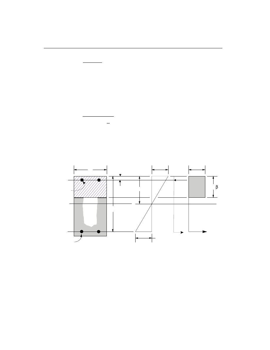
c =
+ f
d
b
y
600
600
.
(NZS 8.4.1.2)
The maximum allowed depth of the compression block is given by
a
c
b
max
= 0.75b
1
.
(NZS 8.4.2 and NZS 8.3.1.7)
• If a
a
£
max
(NZS 8.4.2), the area of tensile steel reinforcement is then given
by
A
M
f
d
a
s
b
y
=
-
æ
è
ç
ö
ø
÷
*
j
2
.
This steel is to be placed at the bottom if M
*
is positive, or at the top if M
*
is
negative.
162
Beam Design
SAP2000 Concrete Design Manual
c
b
d
A
s
a =
c
1
ε
s
A'
s
d'
C
s
T
s
T
c
Strain Diagram
Stress Diagram
Beam Section
α
1 c
f'
ε
= 0.003
Figure VIII-3
Design of a Rectangular Beam Section

• If a
a
>
max
(NZS 8.4.2), compression reinforcement is required (NZS 8.4.1.3)
and is calculated as follows:
– The compressive force developed in the concrete alone is given by
C
f ba
c
=
¢
a
1
max
, and
(NZS 8.3.1.7)
the moment resisted by the concrete and bottom steel is
M
C d
a
c
b
*
=
-
æ
è
ç
ö
ø
÷
max
2
j .
– The moment resisted by compression steel and tensile steel is
M
M
M
s
c
*
*
*
=
-
.
– So the required compression steel is given by
A
M
f
f
d
d
s
s
s
c
b
¢
¢
¢
=
-
- ¢
*
(
)(
)
a
j
1
, where
f
E
c
d
c
f
s
s
y
¢
=
- ¢
é
ëê
ù
ûú
£
0.003
.
(NZS 8.3.1.2 and NZS 8.3.1.3)
– The required tensile steel for balancing the compression in concrete is
A
M
f
d
a
s
c
y
b
1
2
=
-
*
(
)
max
j
, and
the tensile steel for balancing the compression in steel is
A
M
f
d
d
s
s
y
b
2
=
- ¢
*
(
)
j
.
– Therefore, the total tensile reinforcement, A
A
A
s
s
s
=
+
1
2
, and total com-
pression reinforcement is A
s
¢
. A
s
is to be placed at the bottom and A
s
¢
is to be
placed at the top if M
*
is positive, and vice versa.
Beam Design
163
Chapter VIII Design for NZS 3101-95
Design for Flexure of a T-Beam
(i) Flanged Beam Under Negative Moment
In designing for a factored negative moment, M
*
£ 0, (i.e. designing top steel), the
calculation of the steel area is exactly the same as above, i.e., no T-Beam data is to
be used.
(ii) Flanged Beam Under Positive Moment
If M
*
> 0, the depth of the compression block is given by (see Figure VIII-4).
a
d
d
M
f
b
c
b
f
= -
-
¢
2
1
2
*
a
j
,
(NZS 8.3.1)
The maximum allowed depth of the compression block is given by
a
c
b
max
= 0.75 b
1
.
(NZS 8.4.2 and NZS 8.3.1.7)
• If a
d
s
£
(NZS 8.4.2), the subsequent calculations for A
s
are exactly the same
as previously done for the rectangular section design. However, in this case the
width of the beam is taken as b
f
. Whether compression reinforcement is re-
quired depends on whether a
a
>
max
.
• If a
d
s
>
(NZS 8.4.2), calculation for A
s
is done in two parts. The first part is for
balancing the compressive force from the flange, C
f
, and the second part is for
balancing the compressive force from the web, C
w
. As shown in ,
C
f
b
b
d
f
c
f
w
s
=
-
¢
a
1
(
)
.
(NZS 8.3.1.7)
Therefore, A =
C
f
s
f
y
1
and the portion of M
*
that is resisted by the flange is
given by
M
= C
d
d
f
f
s
b
*
-
æ
è
ç
ö
ø
÷
2
j .
Therefore, the balance of the moment, M
*
to be carried by the web is given by
M
= M
M
w
f
*
*
*
-
.
The web is a rectangular section of dimensions b
w
and d, for which the depth of
the compression block is recalculated as
164
Beam Design
SAP2000 Concrete Design Manual
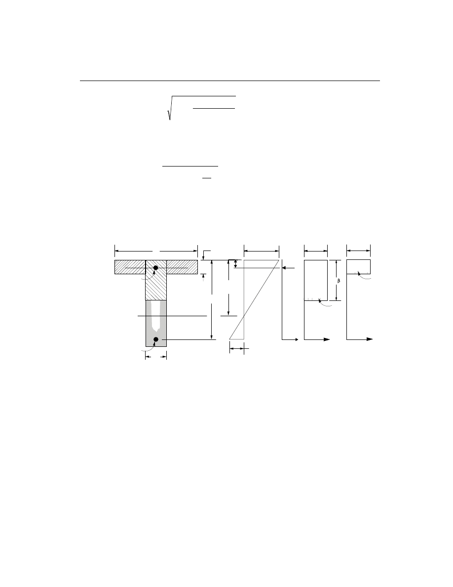
a
d
d
M
f
b
w
c
b
w
1
2
1
2
= -
-
¢
*
a
j
.
(NZS 8.3.1)
• If a
a
1
£
max
(NZS 8.4.2), the area of tensile steel reinforcement is then
given by
A
M
f
d
a
s
w
b
y
2
1
2
=
-
æ
è
ç
ö
ø
÷
*
j
, and
A
A
A
s
s
s
=
+
1
2
.
This steel is to be placed at the bottom of the T-beam.
• If a
a
1
>
max
(NZS 8.4.2), compression reinforcement is required and is cal-
culated as follows:
– The compressive force in the concrete web alone is given by
C
f ba
w
c
=
¢
a
1
max
, and
(NZS 8.3.1.7)
Beam Design
165
Chapter VIII Design for NZS 3101-95
c
b
f
d
A
s
ε
s
d
s
C
f
T
f
C
w
T
w
b
w
A
s
'
C
s
T
s
d'
f
s
'
Beam Section
Stress Diagram
Strain Diagram
a =
c
1
ε
= 0.003
α
1 c
f'
α
1 c
f'
Figure VIII-4
Design of a T-Beam Section
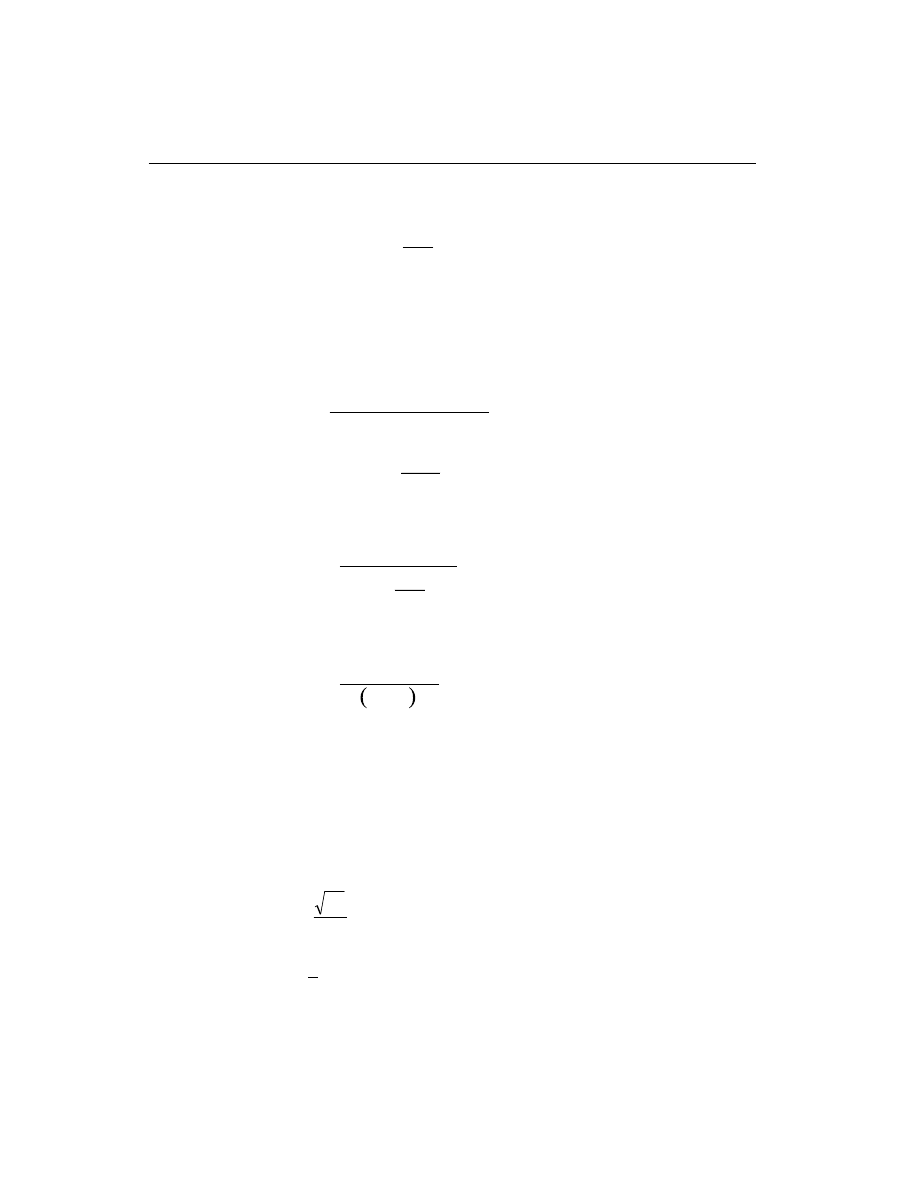
the moment resisted by the concrete web and tensile steel is
M
C
d
a
c
w
b
*
=
-
æ
è
ç
ö
ø
÷
max
2
j .
– The moment resisted by compression steel and tensile steel is
M
M
M
s
w
c
*
*
*
=
-
.
– Therefore, the compression steel is computed as
A
M
f
f
d
d
s
s
s
c
b
¢
¢
¢
=
-
- ¢
*
(
)(
)
a
j
1
, where
f
E
c
d
c
f
s
s
y
¢
=
- ¢
é
ëê
ù
ûú
£
0.003
.
(NZS 8.3.1.2 and NZS 8.3.1.3)
– The tensile steel for balancing compression in web concrete is
A
M
f
d
a
s
c
y
b
2
2
=
-
æ
è
ç
ö
ø
÷
*
max
j
, and
the tensile steel for balancing compression in steel is
A
M
f
d
d
s
s
y
b
3
=
- ¢
*
j
.
– Total tensile reinforcement, A
A
A
A
s
s
s
s
=
+
+
1
2
3
, and total compres-
sion reinforcement is A
s
¢
. A
s
is to be placed at the bottom and A
s
¢
is to be
placed at the top.
Minimum and Maximum Tensile Reinforcement
The minimum flexural tensile steel provided in a rectangular section in an Ordinary
and Elastic moment resisting frame is given by the minimum of the two limits:
A
f
f
b d
s
c
y
w
³
¢
4
, or
(NZS 8.4.3.1)
A
A
s
s required
³
4
3
(
)
.
(NZS 8.4.3.3)
166
Beam Design
SAP2000 Concrete Design Manual

An upper limit of 0.04 times the gross web area on both the tension reinforcement
and the compression reinforcement is imposed upon request as follows:
A
b d
b d
s
w
£ ìí
î
0.04
Rectangular beam
0.04
T -beam
A
b d
b d
s
w
¢
£ ìí
î
0.04
Rectangular beam
0.04
T -beam
Additional Consideration for Seismic Design
For Seismic moment resisting concrete Ductile frames and frames with Limited
ductility (not Elastically responding structures), the following additional condi-
tions are enforced for beam design (NZS 8.5.3.2 and NZS 17.3.5.4). See Table
VIII-2 for comprehensive listing.
• The minimum tensile longitudinal reinforcement shall be provided at both at
the top and bottom for both Ductile frames and frames with Limited ductility.
Any of the top and bottom reinforcement shall not be less than A
s min
(
)
if tensile
reinforcement is required.
A
f
f
b d
c
y
w
s(min)
³
¢
4
.
(NZS 8.5.3.2)
• The beam flexural tensile steel is limited to a maximum given by
A
b d
s
w
£ 0.025
and
(NZS 8.5.3.2, NZS 17.3.5.4)
A
f
f
b d
s
c
y
w
£
+
¢
10
6
.
(NZS 8.5.3.2, NZS 17.3.5.4)
• At any section of a beam within a potential plastic hinge region for Ductile mo-
ment resisting frames, as defined later on page 171, the compression reinforce-
ment area, A
s
¢
, shall not be less than1 2 of the tension reinforcement area, A
s
, at
the same section (NZS 8.5.3.2). At any section of a beam within a potential
plastic hinge region for moment resisting frames with Limited ductility, the
compression reinforcement area shall not be less than 3 8 of the tension rein-
forcement area at the same section (NZS 17.3.5.4).
• At least1 4 of the larger of the top flexural reinforcement required at either end
of the beam in a Ductile frame or in a frame with Limited ductility shall be con-
tinued throughout its length (NZS 8.5.3.2, 17.3.5.4).
Beam Design
167
Chapter VIII Design for NZS 3101-95

Design Beam Shear Reinforcement
The shear reinforcement is designed for each load combination at a user defined
number of stations along the beam span. In designing the shear reinforcement for a
particular beam for a particular loading combination at a particular station due to
the beam major shear, the following steps are involved:
• Determine the factored shear force, V
*
.
• Determine the shear stress, v
c
, that can be resisted by the concrete.
• Determine the reinforcing steel required to carry the balance.
For Seismic moment resisting frames, the shear design of the beams is also based
on the overstrength moment capacities of the members.
The following three sections describe in detail the algorithms associated with the
above-mentioned steps.
Determine Shear Force and Moment
• In the design of the beam shear reinforcement of an Ordinary moment resist-
ing concrete frame, the shear forces and moments for a particular load combi-
nation at a particular beam section are obtained by factoring the associated
shear forces and moments with the corresponding load combination factors.
• In the shear design of Seismic moment resisting Ductile frames and frames
of Limited ductility (NOT Elastically responding frames), however, the shear
force,V
*
, is calculated from the overstrength moment capacities of each end of
the beam, and the gravity shear forces (NZS 4.4.1.1). The procedure for calcu-
lating the design shear force in a beam from overstrength moment capacity is
the same as that described for a column in section “Column Design” on page
154 (NZS 8.5.1.3). See also for more details.
The design shear force, V
*
, is then given by (NZS 4.4, NZS 17.3.7.1)
V
V + V
p
D+ L
*
=
(NZS 4.4, NZS 17.3.7.1)
where, V
p
is the shear force obtained by applying the calculated overstrength
moment capacities at the two ends of the beams acting in two opposite direc-
tions. Therefore, V
p
is the maximum of V
P
1
and V
P
2
, where
V
=
M
+ M
L
P
I
-
J
+
1
, and
168
Beam Design
SAP2000 Concrete Design Manual

V
=
M
+ M
L
P
I
+
J
-
2
,
where
M
I
+
= Moment capacity at end I, with bottom steel in tension, using a steel
yield stress value of
af
y
and no
j factors (
)
j =1.0 ,
M
J
+
= Moment capacity at end J, with bottom steel in tension, using a steel
yield stress value of
af
y
and no
j factors (
)
j =1.0 ,
M
I
-
= Moment capacity at end I, with top steel in tension, using a steel yield
stress value of
af
y
and no
j factors (
)
j =1.0 ,
M
J
-
= Moment capacity at end J, with top steel in tension, using a steel yield
stress value of
af
y
and no
j factors (
)
j =1.0 , and
L = Clear span of beam.
For Seismic moment resisting frames,
a, is taken as 1.25 for both Ductile mo-
ment resisting frames and frames with Limited ductility (NZS A4.1.6).
j is
taken as 1 (NZS 4.4.3.3). V
D
L
+
is the contribution of shear force from the load
in-span distribution of gravity loads.
Determine Concrete Shear Capacity
The shear capacity provided by the concrete alone, v
c
, is calculated as follows:
• The basic shear strength for a rectangular section is computed as,
v =
A
b d
f
b
s
w
c
0.07
+
é
ë
ê
ù
û
ú
¢
10
(NZS 9.3.2.1)
where,
f
c
¢
£ 70 , and
(NZS 9.3.2.1)
0.08
0.2
f
v
f
c
b
c
¢
¢
£
£
.
(NZS 9.3.2.1)
• For Ordinary and Elastically responding moment resisting frames, the concrete
shear capacity for beams is taken as follows:
v = v
c
b
.
(NZS 9.3.2.1)
Beam Design
169
Chapter VIII Design for NZS 3101-95
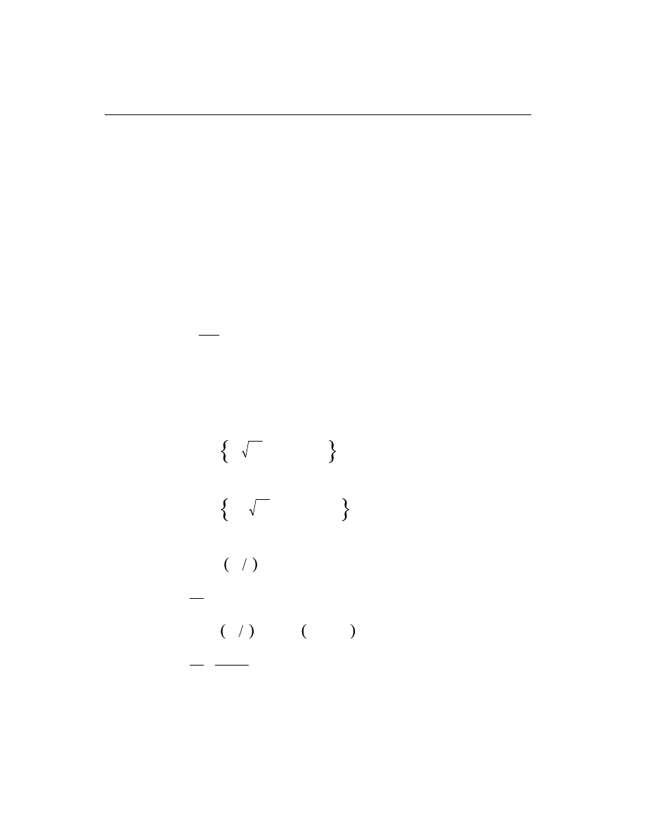
• For Seismic moment resisting Ductile frames, the shear strength of a beam sec-
tion is taken as zero since the axial force is considered to be very small or ten-
sile. This is given as
v =
c
0 .
(NZS 9.4.2.1)
• For Seismic moment resisting frames with Limited ductility, the concrete shear
capacity for the beam is taken as follows:
v =
v
c
b
0.5
.
(NZS 17.3.7.3)
Determine Required Shear Reinforcement
• The average shear stress is computed for a rectangular beam section as,
v =
V
b d
w
*
*
.
(NZS 9.3.1.1)
For other types of sections b d
w
is replaced by A
cv
, the effective shear area
which is shown in Figure VIII-2.
• The average shear stress, v
*
, is limited to a maximum limit, v
max
, which is given
for Ordinary frames and Elastically responding seismic frames as,
v
f
f
c
c
s
max
=
¢
¢
min
,
,
1.1
0.2
MPa
9
j
(NZS 9.3.1.8)
and for Ductile frames and frames with Limited ductility as,
v
f
f
c
c
s
max
=
¢
¢
min
,
,
0.85
0.16
MPa
9
j .
(NZS 9.4.4.2)
• The shear reinforcement per unit spacing is computed as follows:
If v
v
s
c
*
£ j
2 ,
A
s
v
= 0 ,
(NZS 9.3.4.1)
else if
j
j
s
c
s
c
v
v
v
2
<
£
+
*
0.35 ,
A
s
b
f
v
w
yt
=
0.35
,
f
yt
£ 500 MPa
(NZS 9.3.4.3)
170
Beam Design
SAP2000 Concrete Design Manual

else if
j
j
s
c
s
v
v
v
+
<
£
0.35
*
max
,
A
s
v
v
b
f
v
s
c
w
s
yt
=
-
(
)
*
j
j
,
f
yt
£ 500 MPa
(NZS 9.3.6.3)
else if v
v
*
>
max
,
a failure condition is declared.
(NZS 9.3.1.8)
In calculating the design shear reinforcement, a limit is imposed on the f
yt
as
f
yt
£ 500Mpa.
(NZS 3.8.2.1 and NZS 9.3.6.1)
The maximum of all the calculated A
s
v
values, obtained from each load combina-
tion, is reported for the beam along with the controlling shear force and associated
load combination number.
For all beams and at any station, the minimum area of transverse stirrup reinforce-
ment is imposed as follows:
A
s
m A
A
f
f
N
f A
h
v
t
g
c
c
yt
c
c
g
core
³
-
-
ì
í
î
ü
ý
þ
¢
¢
1
r
j
3.3
0.0065
*
(NZS 8.4.7.2)
In potential plastic hinge locations, as described later, of Seismic moment resisting
Ductile frames and frames with Limited ductility, the minimum area of transverse
stirrup is imposed as follows:
A
s
m A
A
f
f
N
f A
h
v
t
g
c
c
yt
c
c
g
cor
³
-
-
ì
í
î
ü
ý
þ
¢
¢
1.3
3.3
0.0060
r
j
*
e
(NZS 8.5.4.3)
In the above two equations for calculating the minimum shear reinforcement, the
following limits are imposed:
A
A
g
c
³ 1.2
(NZS 8.4.7 and NZS 8.5.4.3)
r
t
m
£ 0.4
(NZS 8.4.7 and NZS 8.5.4.3)
f
yt
£ 800 MPa
(NZS 8.4.7 and NZS 8.5.4.3)
For the definition of the potential plastic hinge, it is assumed in the current version
of the program that any beam and column segment near the joint is a potential plas-
tic hinge. The length of the plastic hinge, L
hinge
, in a beam is taken as follows:
Beam Design
171
Chapter VIII Design for NZS 3101-95

L
h
hinge
= 2
(NZS 8.5.3.1)
The column shear reinforcement requirements reported by the program are based
purely upon the above considerations. Any other minimum stirrup requirements to
satisfy spacing and/or volumetric requirements must be investigated independently
of the program by the user.
172
Beam Design
SAP2000 Concrete Design Manual
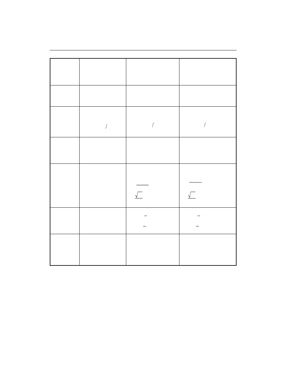
Beam Design
173
Chapter VIII Design for NZS 3101-95
Type of
Check/
Design
Ordinary (non-Seismic)
or Elastically
Responding
(Seismic)
Moment Resisting Frames
with Limited ductility or
Elastically responding
(Seismic)
Ductile Moment
Resisting Frames
(Seismic)
Column
Check
(interaction)
NLD
a
Combinations
NLD
a
Combinations
R
m
= 1
NLD
a
Combinations
R
m
is from NZS Table A3
Column
Design
(Interaction)
NLD
a
Combinations
0.008 <
ρ
< 0.08
0.008 <
ρ
< 18 f
y
(Elastic only)
NLD
a
Combinations
α
= 1.0
0.008 <
ρ
< 18 f
y
R
m
= 1
NLD
a
Combinations
α
= 1.0
0.008<
ρ
< 18 f
y
R
m
is from NZS Table A3
Column
Shears
NLD
a
Combinations
Modified NLD
a
Combs
Column Capacity Shear (V
p
)
ϕ
= 1.0 and
α
= 1.25
NLD
a
Combinations and
Column Capacity Shear (V
p
)
Extra Combo with 1.7 V
E
j = 1.0 and
α
= 1.25
Beam
Design
Flexure
NLD
a
Combinations
NLD
a
Combinations
r £ 0.025
r £
+
¢
f
f
c
y
10
6
r ³
¢
f
f
c
y
4
NLD
a
Combinations
r £ 0.025
r £
+
¢
f
f
c
y
10
6
r ³
¢
f
f
c
y
4
Beam Min.
Moment
Override
Check
No Requirement
A
A
sEND
+
sEND
-
³
3
8
{ }
A
A
sSPAN
+
sEND
³
-
1
4
max
A
A
sEND
+
sEND
-
³
1
2
{ }
A
A
sSPAN
+
sEND
³
-
1
4
max
Beam Design
Shear
NLD
a
Combinations
v
v
c
b
=
NLD
a
Combinations
Beam Capacity Shear (V
p
)
with
α
= 1.25 and
ϕ
= 1.0
plus V
D L
+
v
v
c
b
= / 2
NLD
a
Combinations
Beam Capacity Shear (V
p
)
with
α
= 1.25 and
ϕ
= 1.0
plus V
D+L
v
c
= 0
a
NLD = Number of specified loading
Table VIII-2
Comparison of Ordinary and Seismic Moment Resisting Frame Design


C h a p t e r IX
Design Output
Overview
SAP2000 creates design output in three major different formats
graphical dis-
play, tabular output, and member specific detailed design information.
The graphical display of design output includes input and output design informa-
tion. Input design information includes design section labels, K-factors, live load
reduction factors, and other design parameters. The output design information in-
cludes longitudinal reinforcing, shear reinforcing, and column capacity ratios. All
graphical output can be printed.
The tabular output can be saved in a file or printed. The tabular output includes
most of the information which can be displayed. This is generated for added con-
venience to the designer.
The member specific detailed design information shows the details of the calcula-
tion from the designer’s point of view. It shows the design forces, design section di-
mensions, reinforcement, and some intermediate results for all the load combina-
tions at all the design sections of a specific frame member. For a column member, it
can also show the position of the current state of design forces on the column inter-
action diagram.
Overview
175

In the following sections, some of the typical graphical display, tabular output, and
member-specific detailed design information are described. Some of the design in-
formation is specific to the chosen concrete design codes which are available in the
program and are only described where required. The ACI 318-99 design code is de-
scribed in the latter part of this chapter. For all other codes, the design outputs are
similar.
Graphical Display of Design Output
The graphical output can be produced either as color screen display or in gray-
scaled printed form. Moreover, the active screen display can be sent directly to the
printer. The graphical display of design output includes input and output design in-
formation.
Input design information, for the ACI 318-99 code, includes
• Design section labels,
• K-factors for major and minor direction of buckling,
• Unbraced Length Ratios,
• C
m
-factors,
• Live Load Reduction Factors,
•
d
s
-factors, and
•
d
b
-factors.
The output design information which can be displayed is
• Longitudinal Reinforcing,
• Shear Reinforcing, and
• Column Capacity Ratios.
The graphical displays can be accessed from the Design menu. For example, the
longitudinal reinforcement can be displayed by selecting Display Design Info...
from the Design menu. This will pop up a dialog box called Display Design Re-
sults. Then the user should switch ON the Design Output option button (default)
and select Longitudinal Reinforcing in the drop-down box. Then clicking the OK
button will show the longitudinal reinforcing in the active window.
The graphics can be displayed in either 3D or 2D mode. The SAP2000 standard
view transformations are available for all concrete design output displays. For
switching between 3D or 2D view of graphical displays, there are several buttons
176
Graphical Display of Design Output
SAP2000 Concrete Design Manual

on the main toolbar. Alternatively, the view can be set by choosing Set 3D View...
from the View menu.
The graphical display in an active window can be printed in gray scaled black and
white from the SAP2000 program. To send the graphical output directly to the
printer, click on the Print Graphics button in the File menu. A screen capture of
the active window can also be made by following the standard procedure provided
by the Windows operating system.
Tabular Display of Design Output
The tabular design output can be sent directly either to a printer or to a file. The
printed form of tabular output is the same as that produced for the file output with
the exception that for the printed output font size is adjusted.
The tabular design output includes input and output design information which de-
pends on the design code of choice. For the ACI 318-99 code, the tabular output in-
cludes the following. All tables have formal headings and are self-explanatory, so
further description of these tables is not given.
Input design information includes the following:
• Concrete Column Property Data
– Material label,
– Column dimensions,
– Reinforcement pattern,
– Concrete cover, and
– Bar area.
• Concrete Beam Property Data
– Material label,
– Beam dimensions,
– Top and bottom concrete cover, and
– Top and bottom reinforcement areas.
• Load Combination Multipliers
– Combination name,
– Load types, and
– Load factors.
Tabular Display of Design Output
177
Chapter IX Design Output

• Concrete Design Element Information (code dependent)
– Design Section ID,
– K-factors for major and minor direction of buckling,
– Unbraced Length Ratios,
– C
m
-factors,
– Live Load Reduction Factors.
• Concrete Moment Magnification Factors (code dependent)
– Section ID,
– Element Type,
– Framing Type,
–
d
s
-factors, and
–
d
b
-factors.
The output design information includes the following:
• Column Design Information
– Section ID,
– Station location,
– Total longitudinal reinforcement and the governing load combination,
– Major shear reinforcement and the governing load combination, and
– Minor shear reinforcement and the governing load combination.
• Beam Design Information
– Section ID,
– Station location,
– Top longitudinal reinforcement and the governing load combination,
– Bottom reinforcement and the governing load combination, and
– Major shear reinforcement and the governing load combination.
The tabular output can be accessed by selecting Print Design Tables... from the
File menu. This will pop up a dialog box. Then the user can specify the design
quantities for which the results are to be tabulated. By default, the output will be
sent to the printer. If the user wants the output stream to be redirected to a file,
he/she can check the Print to File box. This will provide a default filename. The
default filename can be edited. Alternatively, a file list can be obtained by clicking
178
Tabular Display of Design Output
SAP2000 Concrete Design Manual

the File Name button to chose a file from. Then clicking the OK button will direct
the tabular output to the requested stream
the file or the printer.
Member Specific Information
The member specific design information shows the details of the calculation from
the designer’s point of view. It provides an access to the geometry and material
data, other input data, design forces, design section dimensions, reinforcement de-
tails, and some of the intermediate results for a member. The design detail informa-
tion can be displayed for a specific load combination and for a specific station of a
frame member. For a column member, it can also show the position of the current
state of design forces on the column interaction diagram.
The detailed design information can be accessed by right clicking on the desired
frame member. This will pop up a dialog box called Concrete Design Information
which includes the following tabulated information for the specific member. If the
selected member is a column, the dialog box includes
– Load combination ID,
– Station location,
– Longitudinal reinforcement area,
– Major shear reinforcement area, and
– Minor shear reinforcement area.
If the selected member is a beam, the dialog box includes
– Load combination ID,
– Station location,
– Top reinforcement area,
– Bottom reinforcement area, and
– Shear reinforcement area.
Additional information can be accessed for column members by clicking on the Re-
Design, Details, and Interaction buttons in the dialog box. For beams additional
information can be accessed by clicking on the ReDesign and Details buttons in the
dialog box.
Additional information that is available by clicking on the ReDesign button is as
follows:
Member Specific Information
179
Chapter IX Design Output

• Design Factors (code dependent)
– Effective length factors, K, for major and minor direction of buckling,
– Unbraced Length Ratios,
– C
m
-factors,
– Live Load Reduction Factors,
–
d
s
-factors, and
–
d
b
-factors.
• Element Section ID
• Element Framing Type
Additional information that is available by clicking on the Details button is given
below. The details of this information depends on whether the selected member is a
beam or a column. If the member is a column, the information includes:
• Frame, Section, Station, and Load Combination IDs,
• Section geometric information and graphical representation,
• Material properties of steel and concrete,
• Design axial force and biaxial moments,
• Minimum design moments,
• Moment factors,
• Longitudinal reinforcing areas,
• Design shear forces,
• Shear reinforcing areas, and
• Shear capacities of concrete and steel.
If the member is a beam, the information includes:
• Frame, Section, Station, and Load Combination IDs,
• Section geometric information and graphical representation,
• Material properties of steel and concrete,
• Design moments and shear forces,
• Minimum design moments,
• Top and bottom reinforcing areas,
• Shear capacities of concrete and steel, and
180
Member Specific Information
SAP2000 Concrete Design Manual

• Shear reinforcing area.
Clicking on the Interaction button displays the interaction diagram in a three di-
mensional space for the column section. The design axial force and the biaxial mo-
ments are plotted on the interaction diagram to show the state of stress in the col-
umn. The interaction diagram can be viewed in any orientation and the view can be
manipulated from the interaction dialog box. The interaction diagram can be
printed for hard-copy output.
Member Specific Information
181
Chapter IX Design Output


References
AASHTO, 1997
AASHTO LRFD Bridge Design Specifications — U.S. Units, 1997 Interim Edi-
tion, American Association of State Highway and Transportation Officials,
1997.
ACI, 1999
Building Code Requirements for Structural Concrete (ACI 318-99) and Com-
mentary (ACI 318R-99), American Concrete Institute, P.O. Box 9094,
Farmington Hills, Michigan, June 1999.
BSI, 1989
BS 8110 : Part 1, Structural Use of Concrete, Part 1, Code of Practice for De-
sign and Construction, British Standards Institution, London, UK, 1985, Issue
2, 1989.
CEN, 1992
ENV 1992-1-1, Eurocode 2: Design of Concrete Structures, Part 1, General
Rules and Rules for Buildings, European Committee for Standardization, Brus-
sels, Belgium, 1992.
CEN, 1994
ENV 1991-1, Eurocode 1: Basis of Design and Action on Structures
Part 1,
Basis of Design, European Committee for Standardization, Brussels, Belgium,
1994.
183

CSA, 1994
A23.3-94, Design of Concrete Structures, Canadian Standards Association,
Rexdale, Ontario, Canada, 1994.
CSI, 1998a
SAP2000 Getting Started, Computers and Structures, Inc., Berkeley, Califor-
nia, 1998.
CSI, 1998b
SAP2000 Quick Tutorial, Computers and Structures, Inc., Berkeley, Califor-
nia, 1998.
CSI, 1997
SAP2000 Analysis Reference, Vols. I and II, Computers and Structures, Inc.,
Berkeley, California, 1997.
ICBO, 1997
Uniform Building Code, International Conference of Building Officials, Whit-
tier, California, 1997.
NZS, 1995
New Zealand Standard NZS 3101, Concrete Structures Standard, Part 1 — The
Design of Concrete Structures, Standards New Zealand, Wellington, New Zea-
land, 1995.
NZS, 1992
New Zealand Standard NZS 4203, Code of practice for General Structural De-
sign and Design Loadings for Buildings, Standards New Zealand, Wellington,
New Zealand, 1992.
PCA, 1996
Notes on ACI 318-99, Building Code Requirements for Reinforced Concrete,
with Design Applications, Portland Cement Association, Skokie, Illinois,
1996.
184
SAP2000 Concrete Design Manual

D. W. White and J. F. Hajjar, 1991
“Application of Second-Order Elastic Analysis in LRFD: Research to Prac-
tice,” Engineering Journal, American Institute of Steel Construction, Inc., Vol.
28, No. 4, 1991.
185
Chapter X


Index
Additional moment
Balanced condition
AASHTO, 61, 63
ACI, 33, 35
BS, 113, 116
Canadian, 89, 91
Eurocode, 135, 138
New Zealand, 162, 165
AASHTO, 59
ACI, 30
British, 111
Canadian, 87
Eurocode, 132
New Zealand, 160
AASHTO, 66
ACI, 38
British, 117
Canadian, 95
Eurocode, 139
New Zealand, 168
Braced frames
British, 107
Canadian, 77
Eurocode, 125
New Zealand, 150
Code total moment
AASHTO, 50, 52
ACI, 23, 25
British, 106, 109
Canadian, 77, 80
Eurocode, 125, 127
New Zealand, 149, 152
AASHTO, 47
ACI, 21
British, 104
Canadian, 75
Eurocode, 123
New Zealand, 147
187

Canadian, 81
Eurocode, 128
New Zealand, 153
Compression reinforcement
AASHTO, 61, 63
ACI, 33, 35
British, 114, 116
Canadian, 90 - 91
Eurocode, 135, 138
New Zealand, 163, 165
Concrete shear capacity
AASHTO, 55, 67
ACI, 28, 40
British, 110, 117
Canadian, 83, 97
Eurocode, 128, 140
New Zealand, 155, 169
Design load combinations, 1, 6
AASHTO, 46
ACI, 17
British, 101
Canadian, 74
Eurocode, 119
New Zealand, 146
Design of T-beams
AASHTO, 62
ACI, 34
British, 114
Canadian, 91
Eurocode, 136
New Zealand, 164
Ductile detailing
ACI, 37
Canadian, 95
New Zealand, 167
Earthquake resisting frames
ductile, 26, 53, 66, 81 - 82, 94, 96, 143,
154 - 155, 167 - 168
elastic, 143
intermediate, 17, 37, 39
limited, 143
nominal, 71, 95, 97
ordinary, 17
shear in intermediate frames, 28, 39
shear in special frames, 27, 54, 66
special, 17, 37 - 38
Element unsupported length, 12
Factored moments and forces
AASHTO, 50, 59
ACI, 23, 31
British, 107, 112
Canadian, 77, 87
Eurocode, 125, 133
New Zealand, 149, 160
Flexural reinforcement
AASHTO, 59
ACI, 31
British, 111 - 112
Canadian, 87
Eurocode, 133
New Zealand, 160
Generation of biaxial interaction surfaces,
AASHTO, 48
ACI, 21
British, 105
Canadian, 75
Eurocode, 123
New Zealand, 147
188
SAP2000 Concrete Design Manual

Canadian, 75
Eurocode, 123
New Zealand, 147
See also P-Delta analysis
Live load reduction factor, 7, 20, 46, 74,
Maximum column reinforcement
AASHTO, 47
ACI, 21
British, 105
Canadian, 75
Eurocode, 123
New Zealand, 147
Minimum column reinforcement
AASHTO, 47
ACI, 21
British, 105
Canadian, 75
Eurocode, 123
New Zealand, 147
Minimum eccentricity
AASHTO, 50
ACI, 23
British, 108
Canadian, 77
Eurocode, 126 - 127
New Zealand, 149
Minimum tensile reinforcement
AASHTO, 65
ACI, 36
Canadian, 94
New Zealand, 166
Moment magnification
British (additional moment), 107
Canadian, 77
Eurocode (total moment), 125
New Zealand, 150
Nonsway frames
AASHTO, 51
ACI, 24
British, 107
Canadian, 77
Eurocode, 125
New Zealand, 150
details, 180
graphical, 175 - 176
interaction diagram, 181
member specific, 175, 179
tabular, 175, 177
Overstrength moment capacity, 154, 168
AASHTO, 51
ACI, 23
British, 108
Canadian, 78
Eurocode, 127
New Zealand, 150
Probable moment capacity, 26, 82
Rectangular beam design
AASHTO, 60
ACI, 32
British, 112
Canadian, 88
Eurocode, 134
New Zealand, 161
189
Index

Shear reinforcement
AASHTO, 56, 68
ACI, 30, 40
British, 110, 118
Canadian, 84, 98
New Zealand, 131, 141, 157, 170
Special considerations for seismic loads,
8, 14
AASHTO, 43, 54, 66
ACI, 17, 27, 37 - 38
Canadian, 71, 82, 96
New Zealand, 143, 154, 168
Strength reduction factors
AASHTO, 47
ACI, 20
British, 104
Canadian, 74
Eurocode, 122
New Zealand, 146
AASHTO, 5, 43
ACI, 5, 17
British, 5, 101
Canadian, 5, 71
Eurocode, 5, 119
New Zealand, 5, 143
Sway frames
AASHTO, 51
ACI, 24
British, 107
Canadian, 77
Eurocode, 125
New Zealand, 150
T-Beam design
Canadian, 91
Eurocode, 136
New Zealand, 164
Unbraced frames
AASHTO, 51
ACI, 24
British, 108
Canadian, 77
Eurocode, 127
New Zealand, 150
AASHTO, 43
ACI, 17
British, 101
Canadian, 71
Eurocode, 119
New Zealand, 143
190
SAP2000 Concrete Design Manual
Document Outline
- Ta ble of Con tents
- CHAP TER I In tro duc tion 1
- CHAP TER II De sign Al go rithms 5
- CHAP TER III De sign for ACI 318-99 17
- CHAP TER IV De sign for AASHTO LRFD 1997 43
- CHAP TER V De sign for CSA-A23.3-94 71
- CHAP TER VI De sign for BS 8110-85 R1989 101
- CHAP TER VII De sign for Eurocode 2 119
- CHAP TER VIII De sign for NZS 3101-95 143
- De sign Load Com bi na tions 146
- Strength Re duc tion Fac tors 146
- Col umn De sign 147
- Beam De sign 160
- CHAP TER IX De sign Out put 175
- Index
- Ad di tional mo ment
- Bal anced con di tion
- Beam flex ural de sign, 2, 8
- Beam shear de sign, 8
- Braced frames
- Check sta tion, 7
- Code to tal mo ment
- Col umn ca pac ity ra tio, 11
- Col umn flex ural de sign, 9
- Col umn shear de sign, 11
- Com pres sion re in force ment
- Con crete shear ca pac ity
- De sign load com bi na tions, 1, 6
- De sign of T-beams
- De tailed out put, 180
- Duc tile de tail ing
- Earth quake re sist ing frames
- El e ment un sup ported length, 12
- Fac tored mo ments and forces
- Flex ural re in force ment
- Gen er a tion of bi axial in ter ac tion sur faces, 10
- Graph i cal out put, 176
- Iden ti fi ca tion of beams, 8
- Iden ti fi ca tion of col umns, 8
- In ter ac tion di a gram, 9
- In ter ac tive en vi ron ment, 1
- Lat eral drift ef fect, 12, 78
- Live load re duc tion fac tor, 7, 20, 46, 74, 104, 122, 146
- Max i mum col umn re in force ment
- Mem ber spe cific out put, 179
- Min i mum col umn re in force ment
- Min i mum ec cen tric ity
- Min i mum ten sile re in force ment
- Mo ment mag ni fi ca tion
- Nom i nal mo ment ca pac ity, 82
- Nonsway frames
- Out put, 1
- Overstrength fac tor, 96
- Overstrength mo ment ca pac ity, 154, 168
- P-Delta anal y sis, 12
- Prob a ble mo ment ca pac ity, 26, 82
- Rect an gu lar beam de sign
- Re de sign, 179
- Shear re in force ment
- Spe cial con sid er ations for seis mic loads, 8, 14
- Strength re duc tion fac tors
- Sup ported de sign codes, 1
- Sway frames
- Tab u lar out put, 177
- T-Beam de sign
- Un braced frames
- Units, 2, 14
- Un sup ported length, 25, 52
Wyszukiwarka
Podobne podstrony:
ESMAP mini grid design manual
ESMAP mini grid design manual
[Instrukcja] GDOT Design Policy Manual Chapter 8 Roundabouts (USA)
Eurocode 2 Design of concrete structures Part 2
Eurocode 2 Design of concrete structures part1 2
HP DesignJet 430 Quick Reference Service Manual
Eurocode 2 Design of concrete structures part4
Eurocode 2 Design of concrete structures Part 1 3
[Instrukcja] GDOT Design Policy Manual Chapter 8 Roundabouts (USA)
Eurocode 2 Design of concrete structures part4
Eurocode 2 Part 3 2006 UK NA Design of concrete structures Liquid retaining and containing struc
HP DesignJet 2000CP, 2500CP Quick Reference Service Manual
HP DesignJet 430, 450C, 455CA Printers Quick Reference Service Manual, Not Orderable English
Eurocode 2 Part 1 1 2004 NA UK Design of concrete structures General rules and rules for buildin
Design Guide 06 LRFD of W Shapes Encased in Concrete
HP DesignJet 430 Quick Reference Service Manual
więcej podobnych podstron