
XXVI
Konferencja
Naukowo-Techniczna
awarie budowlane 2013
H
IRONORI
N
AMIKI
, h-namiki@kyobashi.net
Kyobashi Mentec Co., Ltd., Osaka, Japan
Y.
O
TSIKA
& S.
T
AKAHASHI
Keihan Electric Railway Co., Ltd., Osaka, Japan
BRIDGE MONITORING BY HORIZONTAL DISPLACEMENT
AT GIRDER ENDS
MONITOROWANIE MOSTÓW Z WYKORZYSTANIEM PRZEMIESZCZEŃ
POZIOMYCH NA KOŃCACH UKŁADU NOŚNEGO
Abstract Vertical deflection in response to a live load is often used as an integrated indicator when
diagnosing the soundness of girder bridge structures. Herein, we show how vertical deflection of a girder
can be calculated by measuring the horizontal displacement generated at the ends of the girder.
The horizontal displacement generated at a girder end can then be used as a new indicator in place of
measuring vertical deflection at the span center. Additionally, we show that the horizontal force acting
on aged bearings can be calculated from measured horizontal displacement at the upper and lower ends
of a girder, allowing the sliding function of such bearings to be monitored and evaluated. In the near
future, horizontal displacement at girder ends will be routinely measured in the course of bridge health
monitoring.
Streszczenie Przemieszczenia pionowe spowodowane obciążeniem użytkowym są często traktowane
jako zintegrowany wskaźnik jakości konstrukcji. W niniejszej pracy pokazano, jak można ustalić wiel-
kość przemieszczeń pionowych na podstawie pomiaru przemieszczeń poziomych występujących na koń-
cach układu nośnego. Przemieszczenia poziome występujące na końcach układu nośnego mogą być trak-
towane jako nowy wskaźnik jakości konstrukcji zamiast mierzenia przemieszczeń pionowych w środku
rozpiętości przęseł. Ponadto pokazano, że siła pozioma działająca na skrajne łożysko może być wyzna-
czona na odstawie pomiaru przemieszczeń poziomych górnej i dolnej krawędzi dźwigara, pozwalając na
monitorowanie i wyznaczanie funkcji przesuwu takich łożysk. W bliskiej przyszłości przemieszczenia
poziome na końcach dźwigarów będą rutynowo mierzone w celu monitorowania jakości mostów.
1. Introduction
Structural health monitoring techniques are systems consisting of monitoring techniques
and soundness diagnostics. For a large structure such as a bridge, important challenges include
the choice of an appropriate monitoring location, and which characteristics to monitor.
Vertical deflections in response to live loads are often used as an integrated indicator when
diagnosing structural soundness because excessive increases in deflection may be due to girder
corrosion and erosion of material, the decline of elastic coefficients over time, stiffness
degradations of main girders due to joint defects, and other pertinent causes. Vertical
deflections in a bridge are generally measured to evaluate structural soundness, but measuring
such deflections is often difficult, especially near the span center, because bridges typically
span long distances, such as across a river, which makes fixed point location problematic.
932
Namiki H. i in.: Bridge monitoring by horizontal displacement at girder ends
When trains pass along a bridge, each girder bends in response to the changing positions
of the train axles on each girder, and horizontal displacements at the girder ends occur
according to the deflection angle generated by vertical deflections. For a given bridge type,
such as simple girder or continuous girder, vertical deflections at the span center are propor-
tionately linked with horizontal displacements at the girder ends. Unlike vertical displacements
at span centers, horizontal displacements generated at the end of a girder can be easily
measured using precision displacement sensors.
In this paper, we show how the horizontal displacement generated at girder ends can be
used as a new indicator in place of using vertical deflection at the center of a span.
Additionally, we show that the horizontal force acting on a bearing can be calculated from the
horizontal displacement observed at the upper and lower position of girder ends, and describe
how the sliding function of bearings can be evaluated by monitoring horizontal displacements.
Furthermore, horizontal displacements at girder ends are observed in the field and then
compared with calculated displacements. Measurements carried out before, during, and after
the repair of girder bearings can be used to estimate their capability and performance before
and after repair work.
2. Relation between vertical and horizontal deflection
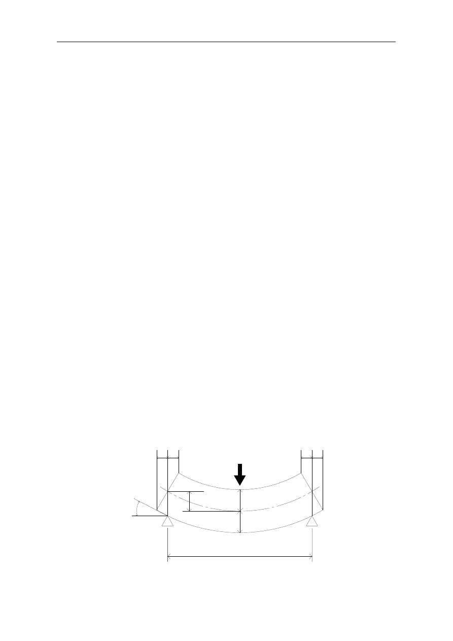
When a concentrated load W acts at the center of a girder span, as shown schematically in
Figure 1, the maximum vertical deflection
δ
v at the span center and the deflection angle i at
the girder end are obtained as shown in Eq. (1) and (2), respectively.
Note that the shear deformation of the girder is not considered in the deflection.
δ
v
= WL
3
/ 48 EI = 0.02083 WL
3
/ EI
(1)
i = WL
2
/ 16 EI = 0.06250 WL
2
/ EI
2)
where L indicates the span length of the girder, E is the elastic coefficient, and I is the area
moment of inertia. The bearings of the simple girder model are assumed to be undifferentiated
between fixed and movable, and the girder model is deformed symmetrically by loading. The
upper and lower ends of the girder are equally displaced relative to one another in opposite
directions, so the absolute values of the displacements are equal because the girder has its
neutral axis along the midpoint of its cross section. The absolute value
δ
h
is obtained as follows,
where α represents the ratio between the span length L and the height h (α = L/h).
Figure 1. Deflection at girder center and girder end
i
h
δ
L
W
v
δ
h
δ
h
δ
h
δ
Mosty i drogi
933
δ
h
= (h/2) = 1.5
δ
v
(h/L) = 1.5
δ
v
/α
(3)
The ratio between the horizontal displacement at the girder end and the vertical deflection at
the span center is inversely proportional to the ratio α. When α = 20,
δ
h is equal to
δ
v/13.3.
Thus, the horizontal displacement generated at the girder end needs to be measured with a
device that can provide precision that is roughly an order of magnitude higher than that
required for measuring vertical deflection at the center of a span.
3. Relation between neutral axis length and horizontal displacement
The neutral axis length of a girder is assumed to neither expand nor contract axially when
the girder deflects under load, and the neutral axis of a girder is assumed to lie along the middle
of its cross-section. However, when the girder is deformed, the length of the neutral axis
becomes slightly longer than the span length L because the neutral axis assumes the shape of
a deflection curve. When a concentrated load W acts at the span center of a girder, the vertical
deflection Y forms a cubic curve described by Eq. (16)
Y = W(3L
2
X–X
3
) / 48EI (0≦X≦L/2)
(4)
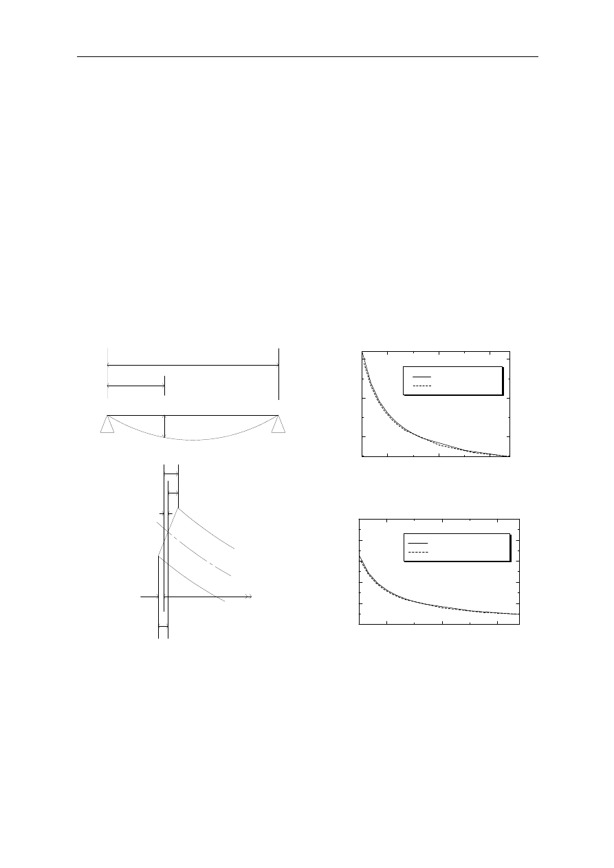
Figure 3. Change rate of girder length
Figure 2. Deflection at girder end
Figure 4. Horizontal deflections at girder. end
where X indicates the distance from the left support. The neutral axis length of a girder is
calculated by integrating the deflection curve of the girder from X = 0 to X = L, and the length
when deflected is equal to L + 2
δ
hN
.
The x-axis length of the girder is reduced by the amount 2
δ
h
N
by the bending deformation
because the neutral axis length L is constant, as shown in Figure 2. Figure 3 shows the
relationship between the ratio of the deflection
δ
v
to the span length L, and the ratio of decrease
h
δ
hN
δ
hU
δ
hL
δ
h
δ
X
L
1000
2000
3000
0.01
0.02
0.03
L/
δ
G
ir
d
e
r
L
e
n
g
th
C
h
a
n
g
e
R
a
te
Concentrated Load
Distributed Load
1000
2000
3000
1
1.02
1.04
1.06
1.08
1.1
L/
δ
-
δ
h
U
/
δ
h
L
Concentrated Load
Distributed Load

934
Namiki H. i in.: Bridge monitoring by horizontal displacement at girder ends
in the horizontal length of the neutral axis, when the span length is 20 m, the bending moment
is 7500 Nm, and h/L=1/20. The deflection at the span center is inversely proportional to the
area moment of inertia under a constant bending moment. The horizontal length of the neutral
axis decreases according to the deflection
δ
v
.
The decrease ratio of the horizontal length of the neutral axis increases when the ratio of
the deflection
δ
v
to the span length L decreases, regardless of whether the load is concentrated
or distributed. For a bridge that is easily deformed by a live load, such as a railway bridge, the
horizontal length of the neutral axis is reduced by approximately 1% when the ratio of the span
length to the deflection L/
δ
v
is 1,500. The decrease in the horizontal length of the neutral axis
affects the horizontal displacement at the girder ends, and respective horizontal displacements
δ
hU
and
δ
hL
for the upper and lower ends of a girder are as follows.
δ
hU
=
δ
h
+
δ
hN
;
δ
hL
= −
δ
h
+
δ
hN
(5)
where
δ
hN
indicates the decrease in the horizontal length of the neutral axis. The horizontal
displacements
δ
hU
and
δ
hL
are positive when the girder contracts axially. Figure 4 shows the
relationship between the ratio L/
δ
v
and the ratio −
δ
hU
/
δ
hL
. The ratio −
δ
hU
/
δ
hL
approaches a value
of 1 as the vertical deflection approaches zero. The upper end of the girder is displaced
approximately 2% more than the lower end when L/
δ
v
= 1,500. These characteristics are
essentially independent of the load type, concentrated or distributed.
4. Restraint of horizontal displacement
One consequence of the deterioration in the sliding function of a bridge bearing due to age
is that the horizontal displacement at the girder end is restrained and horizontal forces acting
upon the bearing are increased. Here, the substructure is assumed not to be deformed by
horizontal forces, i.e., the substructure is assumed to be absolutely rigid. Hereinafter, the
horizontal displacement at the girder end is estimated under this condition.
Due to deterioration in the sliding function of bearings as they age, the horizontal
displacement at girder ends may be restrained and binding forces can act on bearings so that
they rotate toward the bridge axis. Here, the binding force acting on a bearing is estimated
when a concentrated load acts at the center of a simple girder.
The bending moment M
RH
generated by binding force R
H
at the bearing is equal to R
H
(h/2).
When bending moment M
RH
acts at both ends of a girder, the deflection angle i and the
horizontal displacement
δ
M
RH
at the girder end are obtained as follows.
i = M
RH
L/2 EI
(6)
δ
M
RH
= (
h
/2) M
RH
L/2 EI
(7)
Binding force R
H
acts as a compressive force along the bridge axis and the horizontal
displacement ∆L generated by this force is obtained as follows.
∆L = (L/2) R
H
/EA
(8)
where A and E indicate the sectional area and the elastic coefficient of the girder. When both
lower ends of a girder are fixed, the horizontal displacement generated at a girder end in
response to a vertical deflection as shown in Eq. (3) is equal to the sum of
δ
M
RH
and ∆L, as
shown in Eq. (9).
Mosty i drogi
935
δ
h
= WL
2
h/32 EI =
δ
M
RH
+∆L = L h
2
R
H
(1+β/2) / 8 EI
(9)
The binding force RH is obtained from Eq. (10).
R
H
= (L/h) W / { 2(2+β) }
(10)
where the relationship between the cross-sectional area of the girder and the area moment of
inertia is defined as follows.
A = (1 / β) (8 I / h2)
(11)
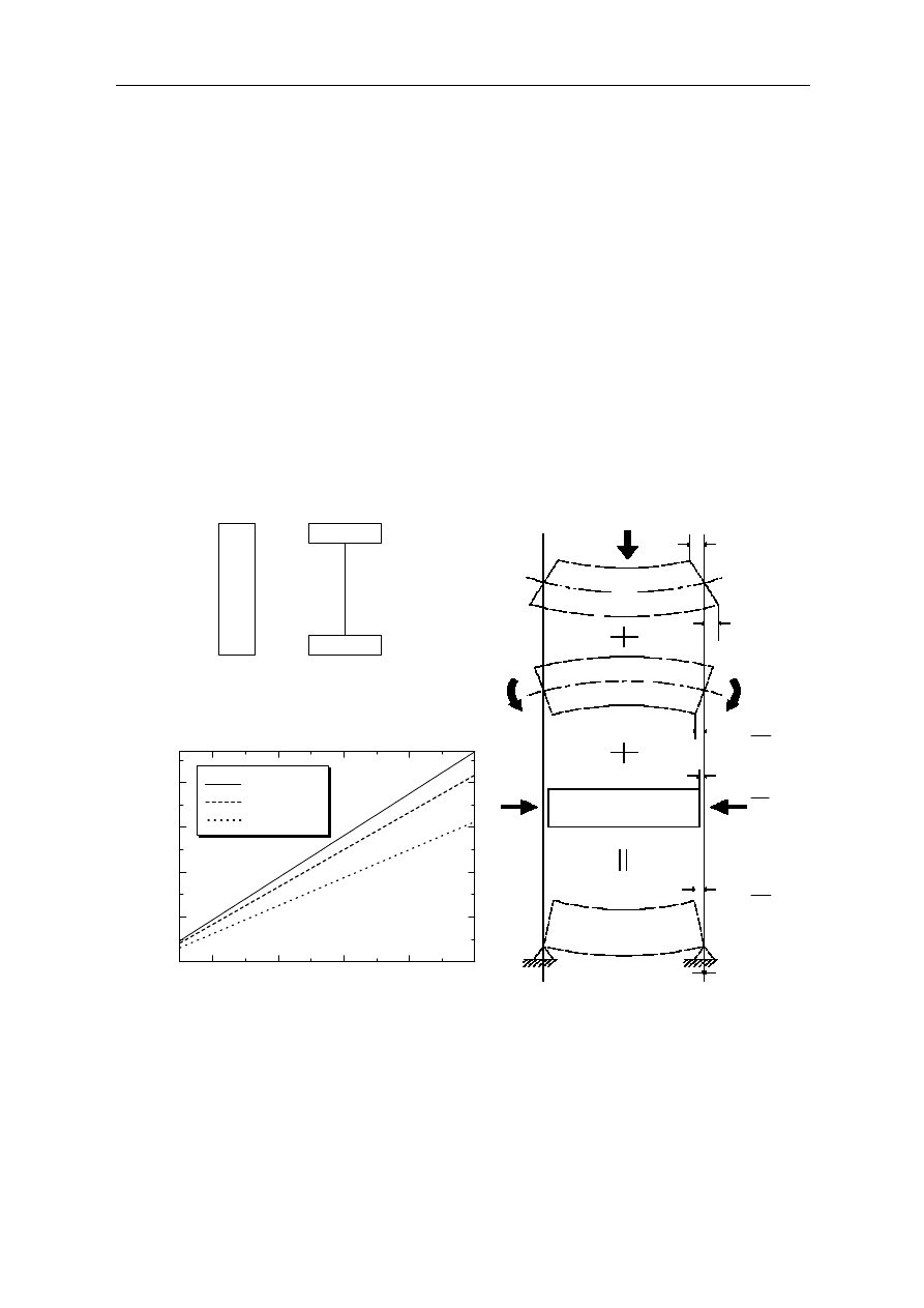
The value of β is close to 1 for the cross-section area of a typical girder. When β = 2, a
girder would have no cross-sectional area, and the girder shown in the left side of Figure 5 has
a rectangular cross-section with β = 2/3. The values of R
H
,
δ
M
RH
and ∆L are obtained using α
and β as follows.
R
H
= αW / {2(β+2)};
δ
M
RH
= 2
δ
h
/ (
β
+2); ∆L =
δ
h
β / (β+2)
(12)
Figure 5. β value
Figure 6. Girder with fixed bearings at both ends
Figure 7. Restriction force at girder end
Figure 7 shows the relationship between L/h (= α) and the binding force R
H
. The horizontal
displacement at the upper end of the girder is obtained as follows.
δ
UP
=
δ
h
−
δ
MRH
+∆L = 2 β
δ
h
/ (β+2)
(13)
β
=2/3
β
=2
h
δ
3
2
h
δ
3
2
h
δ
h
δ
3
1
10
20
30
40
50
0
2
4
6
8
L
/
h
R
H
/
W
β
= 0.6667
β
= 1
β
= 2
936
Namiki H. i in.: Bridge monitoring by horizontal displacement at girder ends
When α = 20 and β = 1, horizontal displacements
δ
MRH
= (2/3)
δ
h, and ∆
L
= (1/3)
δ
h
and
δ
UP
=
= (2/3)
δ
h
are obtained from Eq. (12) and (13), respectively. The binding force R
H
is equal to
3.333W. Thus, when a moving load of 100 kN acts over the girder, a binding force of 333 kN
acts at the bearing along the bridge axis. Given the magnitude and repetitive nature of this
loading, deterioration of such bearings and their substructures is practically inevitable.
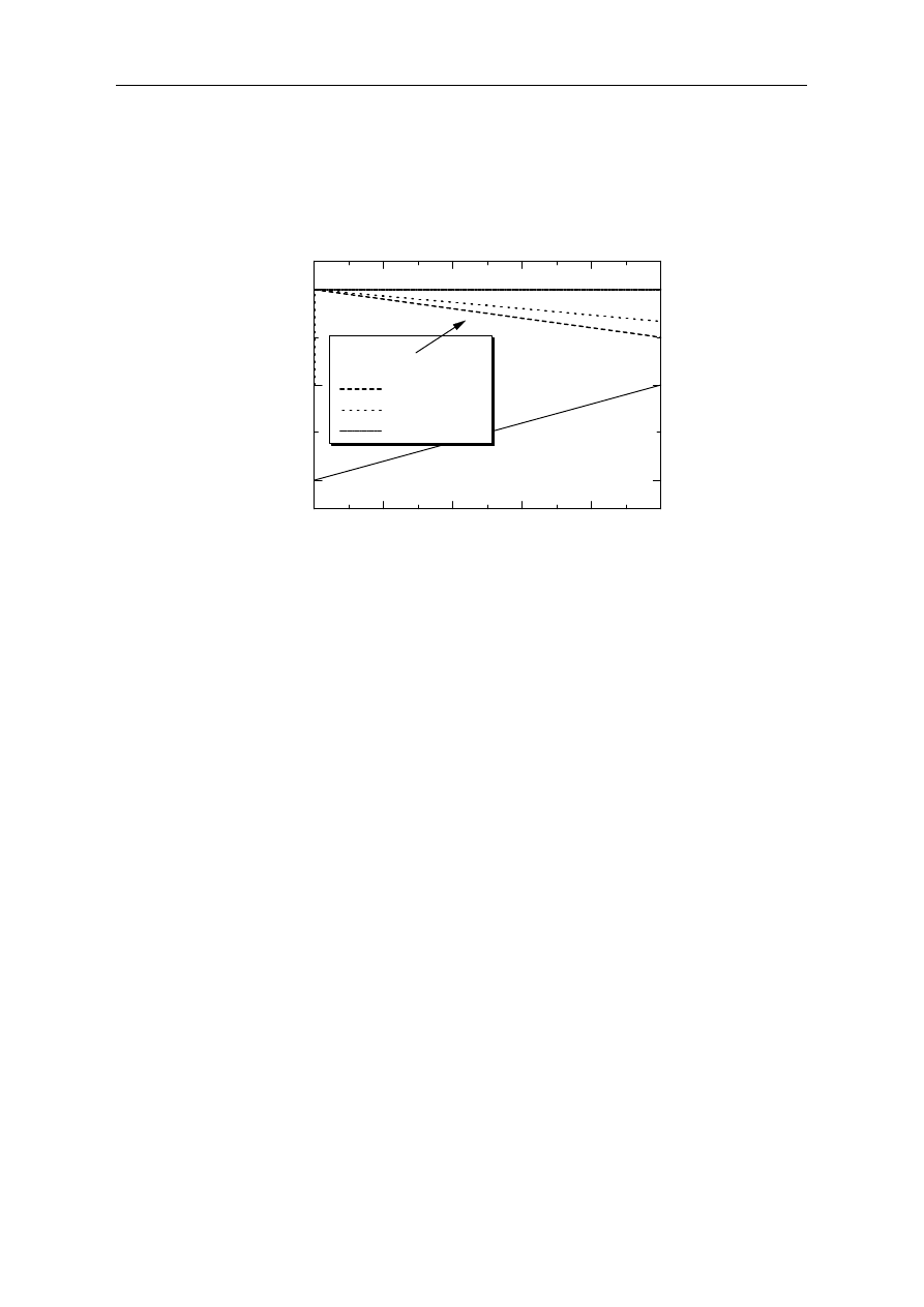
Figure 8. Horizontal deflection ratio at upper and lower girder end.
In the field, the soundness diagnostic of bridge can be evaluated more fully if we extrapo-
late the generated binding force acting upon a bearing from the amount of the horizontal
displacement observed at a girder’s ends. The binding force R and the horizontal displacement
δ
UP
and
δ
LOW
at the upper and lower end of a girder are respectively expressed using γ, as
follows. γ indicates the ratio of the restraint.
R = γ R
H
= α γ W /{ 2(β+2)}
(14)
δ
UP
=
δ
h
−
δ
MRH
+ L=
δ
h
{1+ γ (β
-
2)/ (β+2)}
(15)
δ
LOW
= −
δ
h
+
δ
MRH
+∆L = −
δ
h
(1– γ)
(16)
Figure 8 shows the horizontal displacements at the upper and lower en ds of a girder with
respect to the ratio of the restraint for values ranging from −1 to 1. The horizontal displacement
δ
UP is plotted for β values of 2/3 (= 0.666), 1, and 2.
As shown, the horizontal displacement
δ
UP remains constant when β = 2. Thus, the ratio
δ
UP
/
δ
h
is constant with the ratio γ of the restraint because the magnitudes of the horizontal
displacement
δ
MRH
generated by bending moment M
RH
and the axial displacement caused by
the binding force R
H
are equal and in opposite directions, so the absolute values of the
displacements are equal. The horizontal displacement
δ
LOW
can be used as an indicator to judge
the soundness of a bearing if the substructure is absolutely fixed because the displacement
δ
LOW
depends on the ratio β.
5. Measurement of horizontal displacement
The amount of deflection at a span center under live loading generally ranges from several
millimeters to several centimeters. Therefore, the amount of horizontal displacement at a girder
0
0.2
0.4
0.6
0.8
1
-1
0
1
δ
UP
β
=0.666
β
=1
β
=2
Restriction Rate
δ
U
P
/
δ
h
,
δ
L
O
W
/δ
h
Mosty i drogi
937
end is estimated to range from several hundred micrometers to several millimeters. To measure
dynamic horizontal displacements accurately under live loading conditions such as during the
passage of a train, high-precision displacement sensors that have a resolution of several
micrometers are required. Many devices with sufficient precision are currently available for
making such measurements, and specifications for the sensor used for our measurements are
shown in table 1.
Table 1. The specifications of the sensor
Resolution capacity
∼
0.4
µ
m
Measurement range
0÷10 mm
Responsiveness
8 kHz, 18 KHz
Waterproof performance
IP67
This sensor measures displacement using eddy currents, and high accuracy is possible
because the sensor is a non-contact type that is immune to errors typically encountered when
measuring contact pressure. Moreover, this sensor responds precisely to the low frequency
vibrations that occur in bridges.
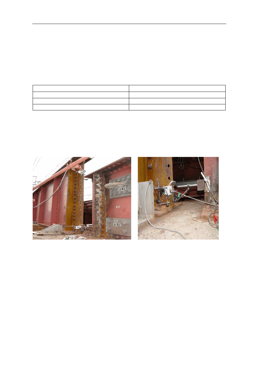
A sensor fixed at one end of one girder with a magnetic stand measures the distance from
a steel fixture at the other end without contact, as shown in Figure 9 and 10.
Figure 9. Installed sensors at girder ends
Figure 10. Sensors for measuring girder deflection
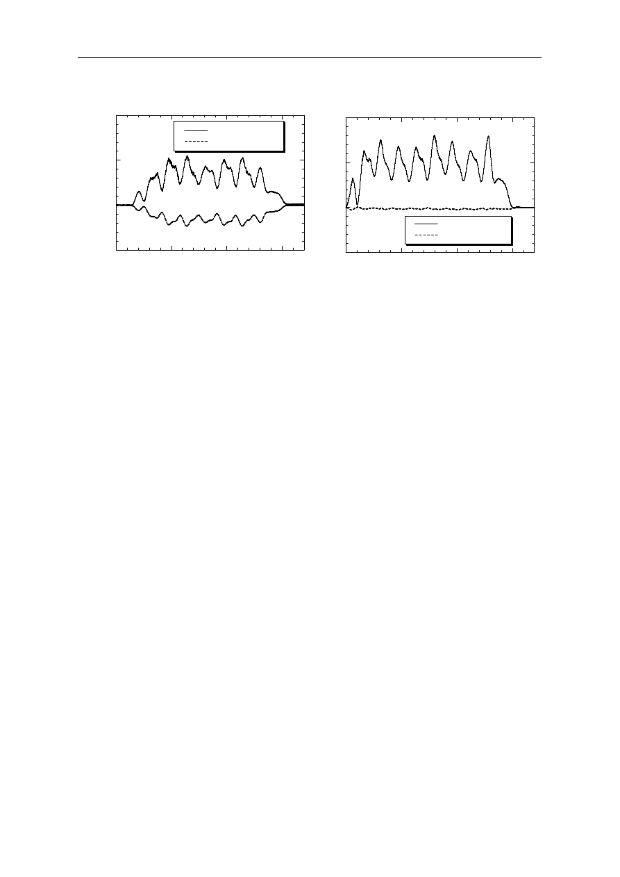
Relative horizontal displacements between the upper and lower girder ends on the 1st pier
were observed before bearing replacement was carried out, and a graph of the dynamic
displacements is shown in Figure 11(a). The relative displacement observed between the lower
ends is far smaller than that of the upper ends of the girders, indicating that the bearings are
restrained and are preventing the horizontal deformations that would be generated by passing
trains were the bearings in good condition. This situation is the result of deterioration in the
sliding function of these bearings, due to age. Figure 11(b) shows the observed displacements
at the upper and lower positions of the girder ends on the 2nd pier after bearing replacement,
when a train passed along the bridge. It was confirmed that the replaced bearings provided the
desired sliding function after the repair.
938
Namiki H. i in.: Bridge monitoring by horizontal displacement at girder ends
a)
b)
Figure 11. Obserbed horizontal displacement(a) before bearing replacement
(b) after bearing replacement
6. Conclusion
In general, vertical deflections are measured to enable evaluation of a bridge structure’s
soundness, but directly measuring such deflections is often difficult.
We showed that the vertical deflection of a girder can be calculated by measuring the
horizontal displacement generated at the upper and lower ends of bridge girders. Furthermore,
the horizontal binding force caused by deterioration in bearing function can be estimated by
measuring the horizontal displacement generated at girder ends.
Girder ends are displaced to a degree approximately 1/10th that of the span center of a
girder under live loads, so a high-precision displacement sensor is required to accurately
measure dynamic horizontal displacements. We verified that horizontal displacements can be
accurately measured using a precision displacement sensor, through the results of
measurements in the field during the course of maintenance work.
References
1.
Yoneda, M., Miyachi,S., A Simplified Method of Estimating Fundamental Natural
Frequency Corresponding to Vertical Mode of Girder Bridges, JSCE, Journal of Structural
Engineering,Vol.38A, 1992.
2.
Yoneda, M., Some Considerations on Damping Characteristics of Bridge Structures due to
Coulomb Friction Force at Movable Supports, Proc. of Japan Society of Civil
Engeers,
Vol.492,1994.
0
5
10
15
-0.5
0
0.5
1
Upper sensor
Lower sencor
H
o
ri
z
o
n
ta
l
d
is
p
la
ce
m
e
n
t δ
h
(
m
m
)
T (sec )
0
5
10
15
-0.5
0
0.5
1
Upper sensor
Lower sensor
H
o
ri
z
o
n
ta
l
d
is
p
la
c
e
m
en
t δ
h
(
m
m
)
T (sec)
Wyszukiwarka
Podobne podstrony:
25 04 J Traczyk Monitoring Mech Vent
Cabot Meg 04 Znak Węża (by MaxFILM)
Irregular Verb Exercises Part 1 by Rob Wilson at Auto
Erika L Foster Werewolf Domination (Abducted By Wolves; Mated at the Full Moon; The Werewolf Cure)
Acceptance and Usage of Open Access Scholarly Communication by Postgraduate Students at the Sokoine
04 STYGMAT CZAROWNIKA (by MaxFILM)
11 Nagao Y i inni Steel plate pre stressing reinforcement for coped steel girder ends
HORIZONTALLY CURVED STEEL BOX GIRDER BRIDGE AASHTO LRFD Design example
Monitor Bridge CAE 3645G
AT 2005 04 1815 PALE
Monitor Bridge CAE 5645
04 Weather Hazards at Sea
USŁUGI, World exports of commercial services by region and selected economy, 1994-04
Monitoring austenite?composition by ultrasonic velocity
Monitor Bridge CAD451S
04 - Kod ramki, Gotowe kody dla chomikow, wszystko co potrzebne by ozdobić Twojego chomika ;)
Bierce An Occurrence at Owl Creek Bridge
Monitoring austenite decomposition by ultrasonic velocity
więcej podobnych podstron