From Workbench Magazine
page 1
©2003 August Home Publishing
One copy permitted for personal use. Other copies prohibited.
All rights reserved
Plans
N O W
w w w . p l a n s n o w . c o m
®
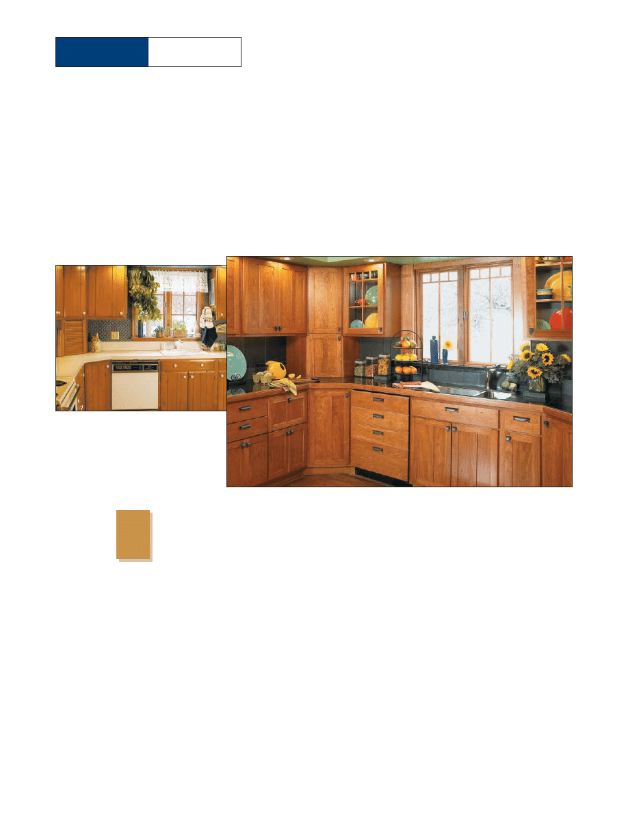
Low-Cost, High-Impact
Kitchen Facelift
ometimes less is more. This kitchen
remodel was considerably less expen-
sive, less time consuming, and required
less demolition than many similar
projects I’ve seen. However, if you compare
the “before” photo with the “after” photo, I
think you’ll agree that this relatively small-
scale project made a big improvement in the
appearance of this kitchen.
One of the biggest improvements was to the
kitchen cabinets. Rather than tear out the old
cabinets, we gave them a “facelift” instead.
BEFORE
{
Although this kitchen was quite
usable, the knotty pine cabinets,
worn countertop, and old appli-
ances all needed updating.
S
AFTER
From Workbench Magazine
page 2
©2003 August Home Publishing
One copy permitted for personal use. Other copies prohibited.
All rights reserved
SHOP-MADE CLADDING
. For
starters, we refaced the existing cabi-
nets by applying shop-made cladding.
The ends of the cabinets are covered
with
1
/
4
"-thick cherry plywood. And we
glued
1
/
4
"-thick strips of solid cherry to
the rails and stiles on the face frames.
SOLID-WOOD DOORS
. As for the
cabinet doors, they needed attention, too.
So we built new frame-and-panel, solid-
wood doors. Making solid-wood panels
for the doors takes more time than using
plywood panels. But once the finish is
applied, it results in a much more uniform
color than using plywood. Solid wood
also mean that the panels look good both
inside and out.
DISPLAY DOORS.
Speaking of looks,
the homeowners had a special collection
of colorful dishes they wanted to display.
The solution was to convert two of the
cabinets into display units by adding glass
doors. Low-voltage lighting installed in
the display cabinets highlights the dishes.
The construction of the display doors
is similar to the solid-wood doors. Here
though, we fit a shop-made divider and a
glass panel into the door frame.
DRAWERS
.Another part of this cab-
inet facelift focused on the drawers. As it
turned out, the existing drawers were
sturdy and well-made, so it didn’t make
sense to build new ones. Instead, we cut
each of the old drawer fronts free on the
table saw.Then, after adding a new front
for the drawer box itself, we installed a
false front made of solid cherry ( page 9.)
FINISH.
But there’s more to this
kitchen remodel than the cabinet facelift.
The water, steam, and spills that are part
of a kitchen’s everyday life demand a tough
finish. To accomplish that, I used a fin-
ishing process that included a stain covered
with three coats of polyurethane.
The rich, warm color you see is pro-
duced by a mixture of three parts Zar
Cherry Stain and one part Wood-Kote
Cherry Jel’d Stain.The gel stain minimizes
blotching that can sometimes occur with
cherry.
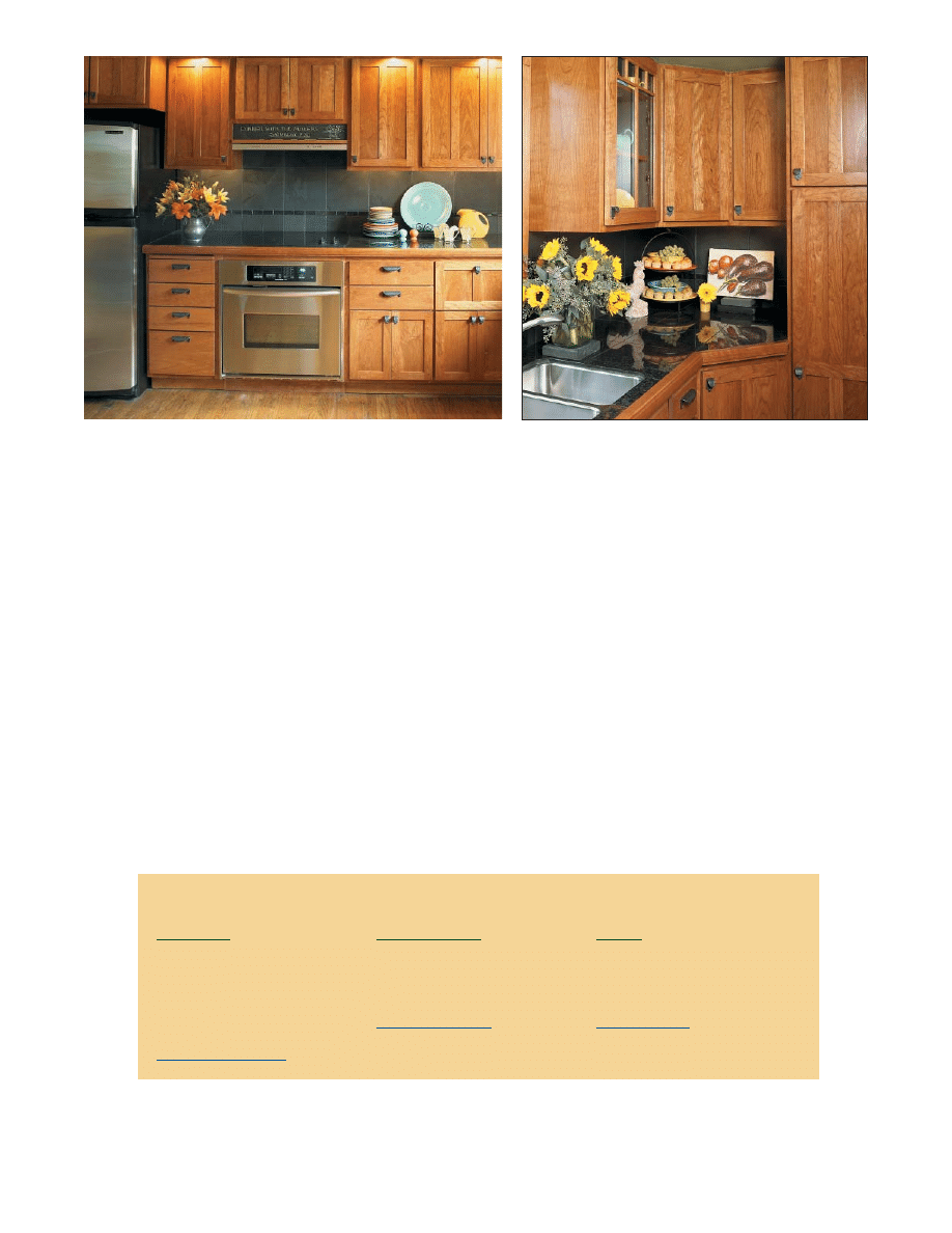
MORE IMPROVEMENTS
. In addi-
tion to the cabinets, we also made several
other improvements to make this kitchen
as functional as it is attractive (see Photos
above). For information about these prod-
ucts, refer to the Buyer’s Guide below.
Appliances
KitchenAid
• Dishwasher (KUDS01FKPA)
• Cooktop (KECC508GBT)
• Vent (KWVU205YBA)
• Oven (KEBC107KSS)
• Refrigerator (KTRC22EKSS)
www.KitchenAid.com
Handles & Pulls
Amerock
Inspiration Series
• Drawer pulls (1592-WID)
• Door pulls (1583-WID)
www.Amerock.com
Hinges
Blum
Compact Series 33
• 110
0
-
1
/
2
" Overlay
Self-Closing Hinges
www.Blum.com
buyer's guide
From Workbench Magazine
page 3
©2003 August Home Publishing
One copy permitted for personal use. Other copies prohibited.
All rights reserved
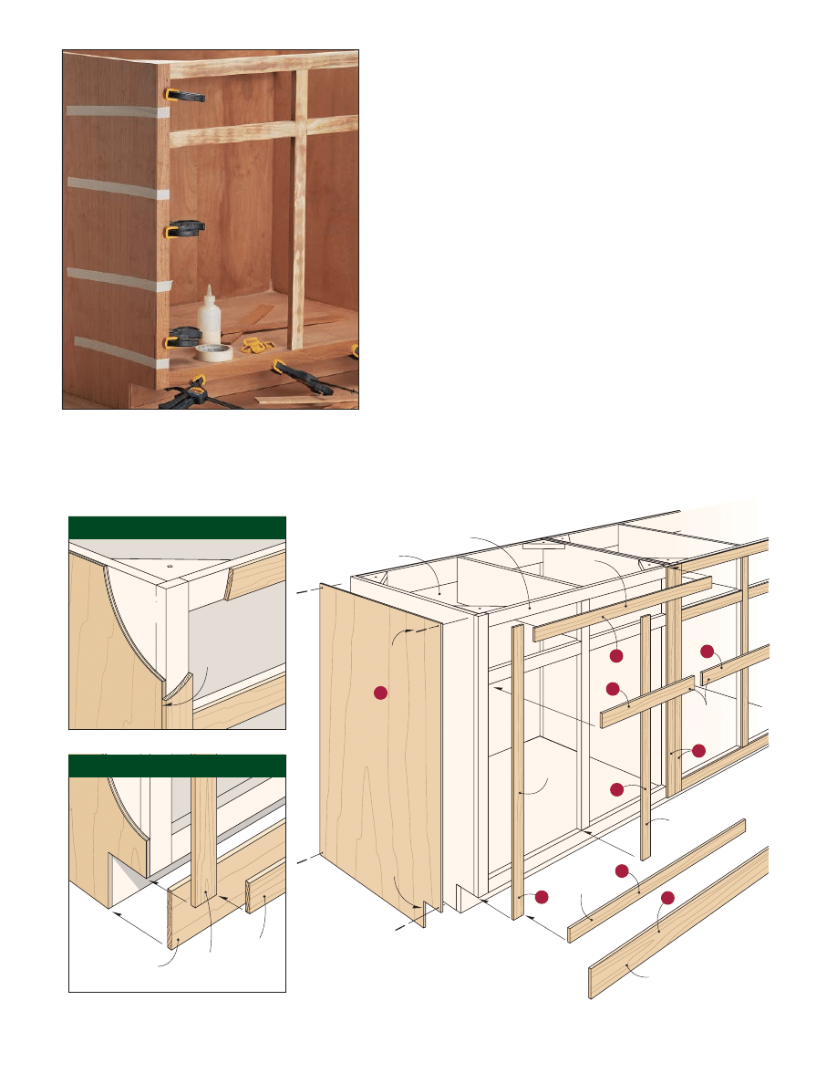
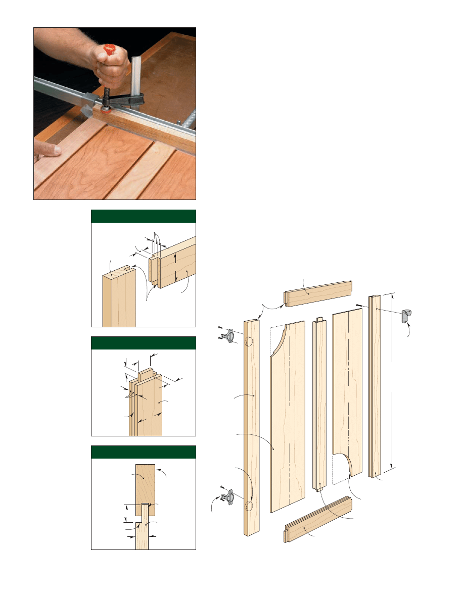
End Panel
(
cherry plywood)
!/4"
Existing Cabinet
Existing Face Frame
2d Finish Nail
3
5
5
6
2
3
4
1
Stile
Cladding
Rail
Cladding
Cut notch to
match toekick
NOTE:
All rail, stile, and toekick cladding
is
-thick solid cherry
!/4"
Rail
Cladding
Rail
Cladding
Stile
Cladding
2
Toekick Cladding
NOTE:
When cladding the
cabinet, follow the
sequence indicated by
the circled numbers
One of the appealing things about a
kitchen facelift is there’s no need to
tear out the existing cabinets. By
covering the old cabinets with cladding,
you can make them look brand new.
MATERIALS
. I used two types of
material for the cladding. The
exposed end panels of the cabinets
are covered with
1
/
4
" cherry ply-
wood (Construction View below). And
I applied
1
/
4
"-thick solid cherry to
the face frames and toekick.
So why not cover the face frames
with veneer instead of solid stock?
Two reasons. First, solid wood lays
flat, so it’s easier to glue and clamp.
Second, the joints can be sanded
flush without worrying about
sanding through the thin veneer.
Getting Started
As with any project, there are a few
preliminary things to take care of
before you get started. First of all,
you’ll need to remove all the cabinet
doors, drawers, and trim.
Once that’s accomplished, check
the outer stile (vertical frame piece)
on the face frame of your cabinets.
Sometimes in order to create a more
finished appearance, the stile extends
past the end of the cabinet, forming
a small lip (Figs. 1 and 1a). If so, you’ll
have to remove it. Otherwise, the
plywood and the solid-wood
cladding won’t fit tightly together.
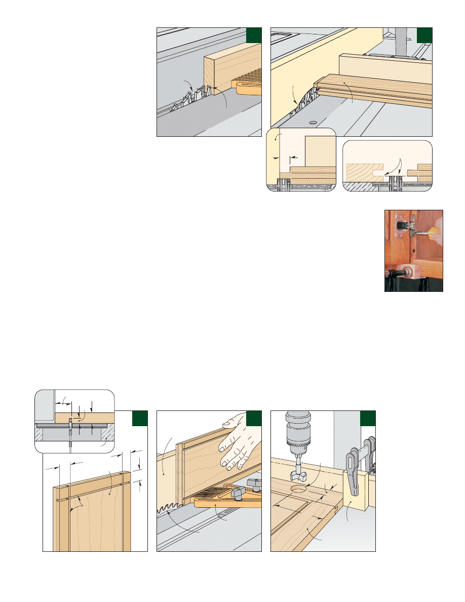
ROUT THE LIP
.An easy way to
remove this lip is to use a router and
a flush trim bit (Fig. 1).As you rout,
CONSTRUCTION VIEW
End
Panel
Rail
Cladding
Toekick
Cladding
Stile
Cladding
End
Panel
Stile cladding
covers edge
of plywood
Existing
Cabinet
{ TT
The face frames of the cabinets are
clad with strips of solid wood that are
glued and clamped in place. I used
tape to "clamp" hard-to-reach areas.
cladding the cabinets
Cladding Detail
Toekick Detail
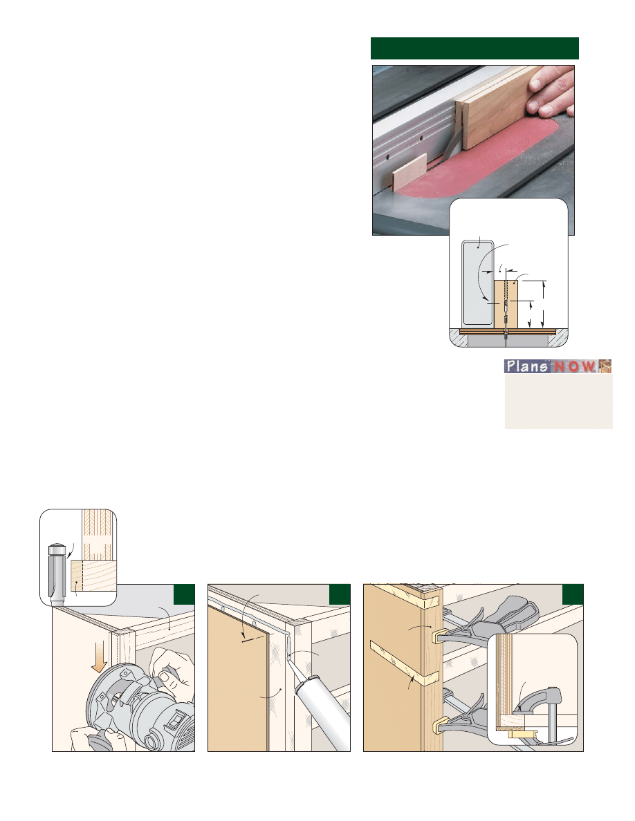
RESAWING ON THE TABLE SAW
From Workbench Magazine
page 4
©2003 August Home Publishing
One copy permitted for personal use. Other copies prohibited.
All rights reserved
the bearing on the bit should ride
against the end of the cabinet (Fig.
1a). This way the cutting edges of
the bit will trim the overhanging lip
flush with the end panel.
Just a note about routing the lip
on the upper cabinets. The base of
the router won’t allow you to rout
the lip near the ceiling.To get around
that, just pare off the lip near the
ceiling with a chisel.
CLEAN & SAND
.After the lip is
removed, clean all the surfaces that
will be clad with a household
degreaser. Then, to ensure a good
glue bond, sand each surface with a
random-orbit sander, using either
80- or 100-grit sandpaper.
Time for the Cladding
Now that the cabinets are prepared,
you can concentrate on the cladding.
END PANELS
. As I mentioned,
the ends of the cabinets are covered
with
1
/
4
" plywood panels. Each panel
is cut to size to fit flush with the
front of the existing face frame.You’ll
also need to cut a notch for the toe-
kick,as shown in the Construction View.
By the way, don’t worry about the
exposed front edge of the plywood.
It will be concealed by the cladding
on the face frame (Cladding Detail).
The end panel is glued on with
panel adhesive.Apply the adhesive to
the cabinet and press the panel into
place (Fig.2).Tack
brads at the cor-
ners of the panel
to keep it from
shifting as the
adhesive cures.
FACE FRAMES
.The next step is
to add the thin, solid-wood cladding
to the face frames. So where do you
get thin wood? A quick and easy way
is to make your own by resawing a
thick board into two (or more) thin
pieces (see Sidebar at right).
When resawing, you’ll want to
work with extra-long pieces that are
ripped to final width. I ripped all
the pieces to match the width of the
rails and stiles on the face frames —
with one exception. To cover the
edge of the
1
/
4
" plywood end panels,
I made the side stile near the exposed
end of each cabinet
1
/
4
" wider.
Keeping those things in mind,
go ahead and prepare the pieces for
resawing. Plan on making a few
extras to allow for mistakes. Then
resaw the stock and plane the
cladding to its final thickness (
1
/
4
").
At this point, it’s time to attach
the cladding to the face frame. I used
simple butt joints where the end of
one strip meets the adjoining piece.
So to produce tight-fitting joints,
it’s important that each piece of
cladding is accurately cut to length.
To accomplish that, follow the
sequence in the Construction View,
cutting each piece of cladding to fit.
As you glue on each piece (I used
yellow glue), make sure the clamping
pressure is evenly distributed across
the cladding (Fig. 3). To get more
“reach,” remove the clamp pad from
the inner jaw (Fig. 3a).
SAND FLUSH.
After gluing on
the cladding, sand the faces flush
with each other. A random-orbit
sander makes quick work of this.
Trim
overhanging
lip flush
Face Frame
Cabinet
End
Panel
adhesive
2d Finish nail
Use masking
tape to "clamp"
outer edge
of cladding
End
Panel
Stile
Cladding
Flush
trim bit
Remove lip
Face
Frame
Cabinet
End
CL
&/8"
#/8"
1
!/2"
#/4"-thick
Stock
Rip fence
Raise blade just
above center
Resawing is cut-
ting thin pieces of
wood from a thick
piece of stock. (In
effect, ripping on
edge.) A quick way
to do this is on the
table saw.
Before you get
started though, there are two
safety precautions that are a
“must.” First, to reduce the
chance of kickback, use a “zero-
clearance” insert with a splitter
(see Photo above). Second, be
sure to use a push block when making a cut.
When resawing, set the rip fence so you end up with
slightly thicker workpieces than needed. That way you
can sand or plane pieces to final thickness.
To avoid bogging down the saw, I use a two-pass
method. Start with the blade raised just over half the
width of the piece (End View). Then make two passes
at this setting, flipping the piece over between passes.
Note: Always keep the same face against the fence.
a.
END VIEW
Remove rubber pad
from clamp for
better reach
a.
1
2
3
FIRST:
Sand face
frame and
end of
cabinet
SECOND:
Attach
end panel
Build a Zero-Clearance Insert
See our Woodworking
Techniques Series
www.PlansNOW.com
From Workbench Magazine
page 5
©2003 August Home Publishing
One copy permitted for personal use. Other copies prohibited.
All rights reserved
The cabinet doors for this kitchen
facelift feature frame-and-panel,
solid-wood construction. For ease
of installation, I decided to make
overlay doors, which means they lay
on top of the face frames. The
amount of overlay is
1
/
2
" on all sides,
so the doors are 1" wider and taller
than the openings in the face frame.
Build the Frames
The first step in building the doors
is to make the frames that surround
the solid-wood panels.
As you can see in the Door
Assembly illustration below, each
frame consists of three vertical stiles
(two sides and a center stile) and two
horizontal rails. Note: For narrow
doors (less than 12" wide), I left out
the center stile.
JOINERY
. To simplify construc-
tion, the frames are assembled with
stub tenon and groove joints. Both
ends of each rail have a short tenon
that fits into a groove in the stile (Rail
& Stile Detail). And a tenon on each
end of the center stile fits into grooves
in the rails (Center Stile Detail).
CONSTRUCTION
. After taking
the joinery into account, cut the rails
and stiles to size from
3
/
4
"-thick hard-
wood. Be sure to label each piece to
avoid getting them mixed up. Also,
mark the outside face to use as a ref-
erence when machining the parts.
CUT GROOVES
. Now you’re
ready to cut grooves in the rails and
stiles. I mounted a
1
/
4
" dado blade in
the table saw to do this (Fig. 4). For
consistent results, run the outside face
of each piece against the fence.
building solid-wood doors
Door
Panel
(
x custom
width and
length)
!/2"
Door Stile
(
x 2")
#/4"
Top Rail
(
x 2")
#/4"
Bottom Rail
(
x 2")
#/4"
Stiles ands rails are
assembled with stub
tenon and groove joints
Center Stile
(
x 2")
#/4"
Rabbet forms a tongue
that fits into groove
Height and width
of finished doors
is 1" larger than
door opening
NOTE:
All rails and
stiles are
custom
lengths
Pull
Door Stile
(
x 2")
#/4"
Door
Panel
!/2"
!/4"
Top Rail
Cut
-wide
!/4"
!/2"
groove,
deep centered
on inside edge
Side Stile
2"
Door
Panel
Door
Frame
Front of
Door
Tongue
#/4"
!/4"
-wide
Rabbet,
deep
!/2"
#/4"
DOOR ASSEMBLY
Center
Stile
Cut
!/4"
!/2"
-wide
grooves,
deep
in both
d
!/2"
!/4"
!/2"
2"
1
!/2"
{ Th
To glue up
a perfectly flat
door, clamp a
straight scrap
of wood
across each
end. Use wax
paper to
avoid gluing
the scrap to
the door.
Rail & Stile Detail
Center Stile Detail
Door Panel Detail
From Workbench Magazine
page 6
©2003 August Home Publishing
One copy permitted for personal use. Other copies prohibited.
All rights reserved
TIME FOR TENONS.
The next
step is to cut stub (short) tenons to
fit the grooves. The tenons are
1
/
2
"
long. So here again, I used a dado
blade, setting it up to cut roughly
5
/
8
" wide. To ensure consistent-
length tenons, use an auxiliary fence
as a stop and “bury” part of the blade
in the fence (Figs. 5 and 5a).
A handy way to establish the
thickness of the tenons is to use one
of the grooved pieces as a gauge for
setting the blade height (Fig. 5b).
Check the setup by making test cuts.
Then cut tenons in the actual work-
pieces, using the miter gauge to
guide each piece through the blade.
Making two passes, one on each side,
should result in a tenon that fits snug.
Solid-Wood Panels
With the door frames complete, it’s
time to start on the solid-wood
panels. Instead of going with a tra-
ditional raised-panel look, I wanted
the door panels to be flat on the
outside for a clean, simple look
(Door Panel Detail).
GLUE UP PANELS.
The door
panels are made by edge-gluing
1
/
2
"-
thick cherry. It’s best to start with
panels that are about 2" larger than
you need in length and width, then
trim them to size after the glue-up.
To determine the final size of the
panels, dry assemble the frames,
measure the openings, and then add
7
/
8
". That’s
1
/
8
" less than the com-
bined depth of the grooves. When
the door is assembled, this will allow
the panel to expand and contract
with changes in humidity.
TONGUES.
If you look at the
Door Assembly illustration again, you
can see there’s a tongue on all four
edges of the door panel that fits into
the grooves in the frame pieces.The
tongue is formed by cutting a rabbet
in the back of the door panel.
To cut the rabbet, I used a two-
step process on the table saw. First,
with the panel lying flat, cut four
shallow, crisscross kerfs (Figs. 6 and 6a).
Second, stand the panel on edge and
run it against a tall auxiliary fence to
remove the remaining waste material,
leaving a
1
/
4
"-thick tongue (Fig. 7).
After sanding the tongues
smooth, dry-clamp the doors to
check for final fit before glue-up. If
you plan to stain the doors, now is
a good time to do it.This way, if the
panel shrinks a bit, it won’t expose
unstained wood.
FINAL ASSEMBLY
.When assem-
bling the doors, keep in mind that
only the rails and stiles are glued
together — the panels should “float”
in the frames to allow for wood
movement. Also, be sure the door is
square and flat while the glue dries
(see photo on page 5).
MOUNT DOORS.
After
removing the clamps and sanding
the doors smooth, the next step is to
drill two large holes in the back of
each door to hold the hinges (Fig. 8).
This requires a 35mm drill bit that’s
designed for just this purpose.
Finally, after staining and finishing
the doors, I installed the hinges and
mounted the doors to the cabinets,
using the alignment tip shown in
the margin.
#/4"
#/4"
#/4"
#/4"
Door Panel
Door
Panel
Featherboard
Raise saw blade
#/4"above table
Tall auxiliary
fence
Door Rails
and Stiles
!/4" Dado
blade
Cut a
!/4"
!/2"
-wide groove
deep,
centered on edge
Auxiliary
rip fence
Door Rails and
Center Stile
Miter gauge
fence
%/8" Dado
blade
3
!/2"
Drill a
35mm
hole,
deep
for hinge
!/2"
!#/16"
Fence
Stop block
Door (facedown)
Set height of dado
blade to match groove
#/4"
Table saw
!/4"
!/2"
Fence
!/2"
Auxiliary
fence
{ Th
To ensure
that all the
doors align,
set each one
on an L-shaped
block that’s
clamped to
the face frame.
Then screw
the hinges to
the cabinet.
a.
b.
a.
6
7
8
4
5
FIRST:
Cut saw kerfs in
panel (Fig. a)
SECOND:
Trim waste (Fig. 7)
From Workbench Magazine
page 7
©2003 August Home Publishing
One copy permitted for personal use. Other copies prohibited.
All rights reserved
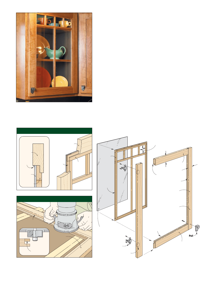
As an option, you may want to
make glass display doors for your
kitchen cabinets. By installing a
wood divider and a piece of glass in
the door frame, it’s easy to convert
a kitchen cabinet into an elegant
display case (Photo at left).
Frame First
The frame for the display doors is
similar to the other doors. It’s an
overlay door that’s 1" larger than the
cabinet opening. Here again, it’s
assembled with stub tenon and
groove joints (Display Door Assembly).
Of course, the thing that’s dif-
ferent about this frame is it’s assem-
bled without a solid-wood panel.
What’s not so obvious is how the
wood divider and the glass fit into
the grooves in the frame.The answer
is, they don’t. Let me explain.
In order to insert the divider and
the glass in the frame, the back lip of
the groove must be removed. This
forms a large rabbet in the back of
the door frame that holds the divider
and glass (Door Frame Detail).
RABBET THE BACK
. An easy
way to trim off the back lip is to lay
the frame face down on a bench and
use a hand-held router with a rabbet
bit (Rabbet Detail). Just a word of cau-
tion here.The lip is fairly thin, which
could cause it to split as you’re
routing.To avoid that, make a couple
of light passes, routing from left to
right.Then, with the bearing riding
against the lower lip, make a full-
depth cut.
The bit will leave rounded cor-
ners, which are easily squared up
with a chisel.This is also a good time
to drill holes for the hinge cups, using
the same method shown on page 6.
display doors & dividers
2"
2"
Divider
Double-strength glass
(cut to fit inside rabbet
in door frame)
Door Stile
(
x 2")
#/4"
Top Rail
(
x 2")
#/4"
Bottom Rail
(
x 2")
#/4"
Rabbet all
four edges of
divider
NOTE:
Arrange muntins to form
four square openings
Stiles and rails are
assembled with stub
tenon and groove joints
(see page 22)
35mm Hole,
deep
!/2"
110 -
Overlay
self-closing hinge
º
!/2"
DISPLAY DOOR ASSEMBLY
Door
Frame
Divider
Rabbet
to fit recess
in back of
door frame
Rout a
-wide
rabbet,
deep
!/2"
!/2"
Assembled
Door Frame
Door
Frame
Silicone
sealant
Glass
Divider
Remove back
lip of groove to
form a rabbet
a.
{
This easy-to-build, elegant display door is
made using simple techniques that can be
applied to any kitchen remodeling project.
Door Frame Detail
Rabbet Detail
STEP 1:
Assemble door frame
without center panel
STEP 2:
Rout a rabbet around
back side of door
(see Rabbet Detail)
From Workbench Magazine
page 8
©2003 August Home Publishing
One copy permitted for personal use. Other copies prohibited.
All rights reserved
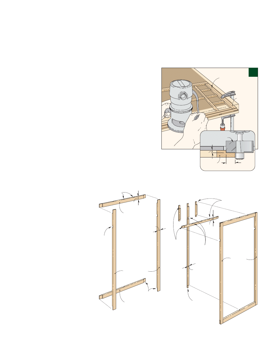
Simple Division
Once the frame is complete, the next
step is to build the wood divider that
creates what appears to be the indi-
vidual panes of glass.The divider is
made up of narrow strips of hard-
wood that are assembled with half-
lap joints (Divider Assembly).
SUB-FRAME & MUNTINS
. As
you can see, the divider consists of a
rectangular sub-frame and several
individual muntins (a fancy word for
window dividers). All of the pieces
for the sub-frame and muntins are
made from
3
/
8
"-thick hardwood.
Although their thickness is iden-
tical, the width of these pieces is dif-
ferent.The rails and stiles of the sub-
frame are 1" wide while the muntins
are only
1
/
2
" wide.
To understand the reason for the
different widths, take a look at the
Door Frame Detail on page 7. Notice
that the divider is rabbeted to fit into
the rabbet in the back of the door
frame.This accomplishes two things.
First, it positions the divider closer to
the front face of the door frame.
Second, since the wider pieces of the
sub-frame are partially concealed
behind the door frame, they will ulti-
mately appear to be the same width
as the muntins (
1
/
2
").
CONSTRUCTION
. Once you
understand how the divider goes
together, construction should go
fairly quickly. Start by planing the
stock for the rails, stiles, and muntins
to thickness. Then simply rip the
pieces to width on the table saw.
To determine the length of these
pieces, measure the shoulder-to-
shoulder distance of the rabbets in
the back of the door frame. Then
cut the rails and stiles of the sub-
frame and the long vertical and hor-
izontal muntins to match.As for the
short muntins, I wanted them to
form four square openings at the top
of the divider, so I cut them to length
accordingly (Display Door Assembly).
HALF-LAPS
. Once the pieces are
cut to length, you can lay out and cut
the half-laps.To get consistent results,
I used a simple jig that attaches to the
miter gauge on the table saw. (For
more on this, see page 11.)
ASSEMBLY
. Now it’s just a
matter of gluing and clamping the
divider together, as shown in Steps 1
and 2 in the Divider Assembly below.
CUT RABBET
.After sanding the
divider smooth, it’s time to cut the
rabbet in the front face of the divider
that I mentioned earlier. Here again,
a handheld router with a rabbet bit
makes quick work of this task (Figs.
9 and 9a).
FINAL DETAILS
. At this point,
you’re almost ready to install the
divider in the door frame. But first,
you’ll need to have a piece of glass
cut to fit into the rabbeted opening
in the back of the frame. (I bought
double-strength glass.) To allow for
wood movement, it should be
1
/
8
"
smaller in length and width than the
opening in the door frame.
To install the glass, lay the door
frame face down on a padded sur-
face. Then fit the divider and glass
into the rabbet. To hold them in
place, apply a small bead of clear sil-
icone sealant around all four edges
(Door Frame Detail). Be sure that the
sealant is forced down into the small
gap between the edge of the glass
and the door frame. Let the door
and glass sit until the sealant cures
fully, usually at least 24 hours.
Sub-Frame Stiles
(
x 1")
#/8"
Sub-Frame
Bottom Rail
(
x 1")
#/8"
Sub-Frame
Top Rail
(
x 1")
#/8"
Half-laps
!/2"
#/16
-wide Half-laps,
deep
"
!/2"
#/16
-wide
Half-lap,
deep
"
1"
1"
NOTE:
Layout half-laps
to form equal size
openings in divider
!/2"
#/16
-wide
Half-laps,
deep
"
Muntins
(
x
)
#/8" !/2"
Sub-Frame
!/2"
!/2"
1"
deep
-wide
Half-laps,
#/16"
Muntin
(
x
)
#/8" !/2"
NOTE:
For information on cutting
half-laps, see page 60
DIVIDER ASSEMBLY
STEP 1
Assemble sub-frame
STEP 2
Glue muntins to sub-frame
Divider
Rout a rabbet in
front face of
divider
!/2"Rabbet
bit
Divider
!/2"
!/8"
a.
9
From Workbench Magazine
page 9
©2003 August Home Publishing
One copy permitted for personal use. Other copies prohibited.
All rights reserved
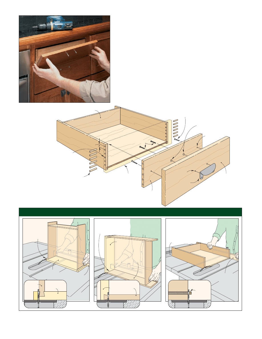
adding new drawer fronts
Building all new drawers for an entire
kitchen can be expensive and time
consuming. Fortunately, I didn’t
have to build new drawers — I just
reused the old drawers and installed
new false fronts, as shown at left.
The type of drawers you have
determines how to replace the drawer
fronts. Some drawers already have a
separate false front mounted to the
drawer box. In that case, just replace
the old false fronts with new ones.
But if the drawer front is an inte-
gral part of the box like mine, it’s a bit
more involved.The old drawer front
has to be trimmed off and then
replaced with a new one (Construction
View below).Then a new false front
is added to the drawer box.
REMOVE FRONTS
. To remove
the old drawer fronts, start by taking
off the slides and pulls.Then use the
table saw to trim off the front, fol-
lowing the three-step process shown
in the illustrations below.
ADD NEW FRONT
. The next
step is to add the new drawer front.
This is a piece of
1
/
2
"-thick hard-
Existing
Drawer Front
Miter gauge
fence
Drawer
Front
Drawer Side
Miter gauge
fence
Rip fence
Drawer
Front
Drawer
Side
Drawer
Front
Drawer
Side
Drawer
Bottom
Drawer
Side
{ TT
To align the
false fronts,
temporarily
screw them to
the drawers.
Then simply
open the
drawer and
install perma-
nent screws.
Remove existing
drawer front
(see Illustrations below)
!/4"
!/2"
Dowels,
1
long
New Drawer Front
(
-thick, cut to fit)
!/2"
Drill
holes,
!/4"
&/16"
1
deep
(see Photo on page 27)
New False
Drawer Front
(
-thick x custom
width and length)
#/4"
Drawer Pull
%/32"
Mounting
hole
Existing Drawer
#8 x 1" Rh Woodscrew
!/2" Clearance holes
for machine screws
!/8" Hole
NOTE:
Make false drawer fronts 1"
larger than face frame opening
Drawer pull
machine screws
!/2"
STEP 1:
Trim drawer
front flush with
drawer sides
STEP 2:
Trim drawer front flush with
ends of the drawer sides
STEP 3:
Trim drawer bottom
flush with ends of
drawer sides
CONSTRUCTION VIEW
TRIMMING OFF DRAWER FRONTS
Dishwasher Door
Metal
Mounting
Panel (supplied)
Upper Spacer
(
x 1")
#/8"
Drawer
Spacers
(
x 1
)
#/8"
!/2"
Drawer
Faces
(
x 6")
#/4"
Lower Drawer Face
(
-thick,
height custom fit)
#/4"
Cut
-wide
rabbets,
deep
!/2"
#/8"
Mounting Screws
(supplied)
Drawer
Pull
!/8"
!/2"
!/4"
Mounting hole
(drill
counterbore,
deep on back)
NOTE:
Glue drawer fronts
and spacers together,
and install drawer pulls
before attaching
to dishwasher
From Workbench Magazine
page 10
©2003 August Home Publishing
One copy permitted for personal use. Other copies prohibited.
All rights reserved
wood cut to fit between the drawer
sides. To make it easy to attach the
false front later, drill a couple of
mounting holes now.Then glue and
clamp the front flush with the ends
of the drawer sides.
DOWELS
.To strengthen the con-
nection, I used
1
/
4
" dowels to “pin”
the joints.This requires drilling holes
through the drawer sides into the
front. To drill these holes quickly
and accurately, I used the drill-press
setup shown in the Photo at right.
Notice that a fence and stop block
are used to position the drawer. I
also used four spacer blocks to index
the location of the dowel holes. To
accomplish this, set the drawer
against the spacer blocks and drill
the first hole.Then remove a spacer
and drill the second hole. Continue
like this until the box is against the
fence and then drill the last hole.
After drilling the holes, glue in
the dowels. They’ll stand a bit
“proud” at this point, so after the
glue dries, just sand the ends smooth.
FINISH & INSTALLATION
.
You’ll want to apply a finish on the
ends of the dowels, as well as the
drawer front. Then reattach the
drawer slides and install the drawers.
Adding the False Fronts
All that’s left to complete this kitchen
facelift is to add the false fronts.
Like the doors, the false fronts
are made from
3
/
4
"-thick hardwood.
Here again, they’re 1" larger than
the opening in the face frame.
Design Note: If a drawer is directly
above a door, it’s more important to
match their widths since even a small
difference is quite noticeable.
ATTACH FALSE FRONTS
.After
cutting the false fronts to size, the
final step is to attach them to the
drawers.To ensure proper alignment,
I used an old trick here.
Start by drilling mounting holes
for the drawer pulls in the false front.
Then hold the false front in posi-
tion and temporarily install screws
through the mounting holes to
attach it to the drawer (Photo on page
9). Next, open the drawer and screw
it to the false front from the back.
Now remove the temporary screws
and drill the mounting holes for the
pulls all the way through the drawer
with an
1
/
8
" bit. Finally, using the
points where the tip of the bit breaks
through as centerpoints, drill
1
/
2
"
clearance holes for the machine
screws used to mount the pulls.
{ T
A set of
1
/
2
"-thick
spacer blocks
makes it easy
to index the
holes for the
1
/
4
" dowels.
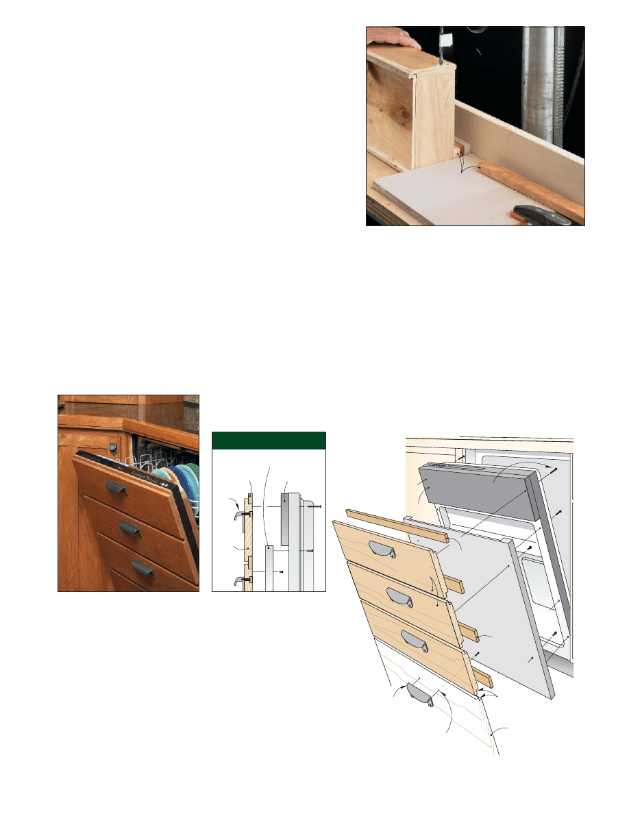
We chose a dishwasher for this project
that’s designed to accept a shop-made,
front panel (a fully-integrated dishwasher).
Most dishwashers like this use a
large plywood door panel. But to tie the
kitchen together, I made a panel that
appears to be a bank of four drawers.
This panel starts out as four drawer
faces made from
3
/
4
"-thick hardwood
(Illustration at right). To create a gap
between the “drawers,” the faces are rab-
beted on the top and bottom
edges to hold
3
/
8
"-thick hard-
wood spacers. Note: To make
the drawer spacing work out, I
also added a spacer strip at the top
to reach the top of the dishwasher
door (Side View Detail).
After gluing the spacers to the
drawer faces to form the panel, it’s
screwed to a metal mounting panel
that’s supplied with the dishwasher.
custom dishwasher panels
Dishwasher
Door
Drawer
Face
Spacer
Mounting Panel
Pull
Stop Block
Drawer
Side
Use tape as
depth stop
New
Drawer
Front
Fence
!/2"-thick Spacer
Blocks
Side View Detail
From Workbench Magazine
page 11
©2003 August Home Publishing
One copy permitted for personal use. Other copies prohibited.
All rights reserved
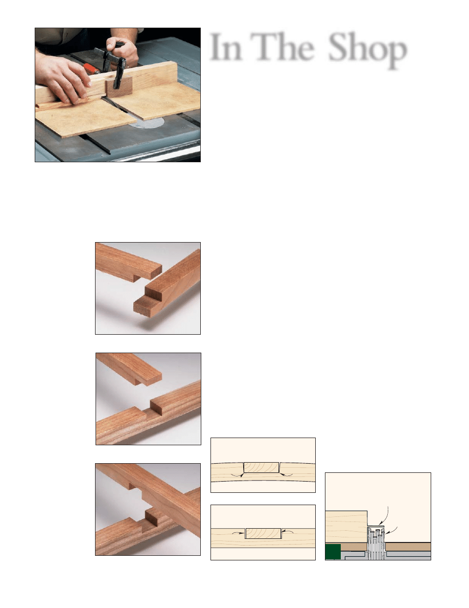
In The Shop
{
{
To use the cutting jig, butt the workpiece against
a stop block clamped in place and use a scrap piece
to hold the stock firmly against the base of the jig.
Then use the miter gauge to slowly guide the jig over
the dado blade to cut the half laps.
>
>
END LAP
Half laps that
join the ends of
two boards pro-
vide plenty of
face-to-face sur-
face for a good
glue joint.
>
>
"T" JOINT
A half lap on the
end of one piece
fits into a dado
in the middle of
the mating piece
to create a T
joint.
>
>
CROSS LAP
Mating half laps
cut in the
middle of two
pieces are often
used to create a
strong grid.
Cutting Half-Lap Joints in Thin Stock
Check blade height
in two passes,
flipping stock
between cuts
Hardboard Base
Shimmed
dado
blade
Test piece
Cutting half-lap joints in narrow, thin
stock on the table saw poses a few
more challenges than working with
thicker stock. Namely, the blade on
the table saw has a tendency to make
thin pieces chatter or bounce more
than thicker pieces as you make a
cut. This can cause an inconsistent
depth of cut, creating a joint where
the faces don’t fit flush.
CUTTING JIG.
One solution is
to use a shop-made jig that attaches to
the miter gauge to support the work-
pieces and raise them off the table
during the cuts (see Photo above).
The jig consists of a hardboard
base screwed to an auxiliary fence. A
stop block clamped to the fence lets
you maintain consistent cuts.
Another advantage of using the
jig is that it bridges the throat plate on
the table saw.This provides a smooth,
flat surface for the workpieces to rest
on all the way through the cut.
Once the jig is made, you’re ready
to cut the lap joints. Depending on
where the cut is made in the work-
piece, this can be an end lap, a T-
shaped lap joint, or a cross lap (see
Photos at left).
Regardless of the type of lap
joint, the goal is the same. The
mating pieces should fit snug (not
tight), and the faces should be flush.
Both of these are accomplished with
the proper setup.
PROPER SETUP
Getting a snug-fitting joint is simply
a matter of shimming the dado blade
to match the width of your stock.
You don’t want to have to force the
joint together.The pressure can cause
the thin stock to bow (Joint Too Tight).
Likewise, there shouldn’t be any vis-
ible gaps between the shoulders (Joint
Too Loose).
SET DEPTH OF CUT.
Next, set
the height of the dado blade so it’s
a little less than half the thickness of
the workpiece.Then make some test
cuts in a piece of scrap (scrap should
be same thickness as the final stock)
to sneak up on the final depth of
cut (Fig. 1).
To do this, make a cut on one
end of the test piece, using the jig
and miter gauge to guide the test
piece. Now flip the piece over and
make a second cut on the same end.
At this point, you should have a thin
sliver of material remaining.
Next raise the dado blade a hair
and repeat the process. This time
around, remove a little from each
side of the sliver until it completely
disappears on the second cut.
CHECK THE FIT.
Now before
cutting the final half-lap joints in
the actual stock, double-check the
blade setup by cutting a half lap on
the end of a couple of test pieces.
Then check the fit to make sure the
faces are flush.
If everything looks good and you
don’t have to force the pieces together,
go ahead and cut the final joints.
Forced joint can cause bowing
Dado width too narrow
Pressure
Pressure
Loose fit makes a sloppy joint
Dado width too wide
Gap
Gap
JOINT TOO TIGHT
JOINT TOO LOOSE
1
Wyszukiwarka
Podobne podstrony:
Cabinet Kitchen Island
Cabinet Kitchen Pantry
Cabinet Kitchen Moveable workstation
Cabinet kitchen cabinet
Plan and Install Kitchen Cabinets
Kitchen Base Cabinet
(Ebooks) Diy Woodwork Plans Kitchen Cabinets
Cabinet movable kitchen island
Plan and Install Kitchen Cabinets
Cabinet Slide out kitchen bin
Cabinets Build Your Own Kitchen Cabinets
face painting lesson 3 id 16748 Nieznany
28 Test „bolesny łuk”, test Lift off, test Yergasona, test “pustej puszki” – wykonanie i
clean kitchen
Corner Buffet Cabinet(1)
Lift a lifting3
więcej podobnych podstron