CLUTCH
1993 Mitsubishi Montero
1993 Clutch
Dodge Ram-50, Mitsubishi Montero, Pickup
DESCRIPTION
All models use diaphragm spring, single-disc type clutches.
Clutch is cable-operated on RWD models, and hydraulically operated on
4WD models.
ADJUSTMENTS
CLUTCH PEDAL HEIGHT & FREE PLAY
Pedal Adjustment (RWD)
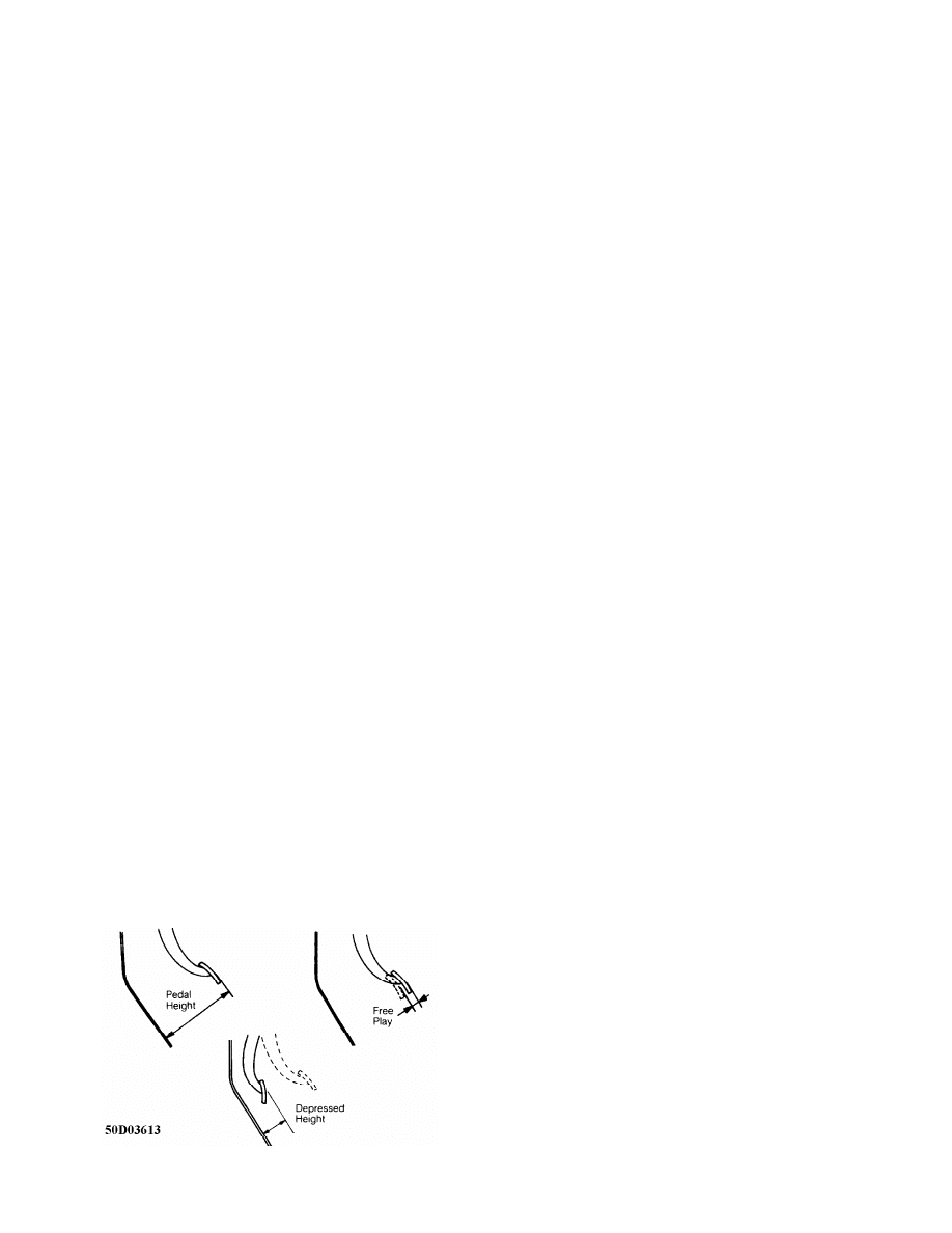
1) To adjust pedal height, loosen stopper bolt lock nut or
clutch switch at top of pedal, and rotate stopper or switch until
correct pedal height is obtained. Measure distance between face of
clutch pedal and floor board. See CLUTCH PEDAL SPECIFICATIONS TABLE.
See Figs. 1-4.
CLUTCH PEDAL SPECIFICATIONS TABLE
Application In. (mm)
Montero
Free Play ............................... .24-.51 (6-13)
Pedal Height
Pedal Depressed (1) ........................... 1.4 (35)
Pedal Released ....................... 7.3-7.5 (185-190)
Pickup & Ram-50
2.4L Free Play .......................... .8-1.4 (20-35)
Pedal Height
Pedal Depressed (1) .......................... 2.4 (60)
Pedal Released ...................... 6.5-6.7 (166-171)
3.0L Free Play ........................... .31-.67 (8-17)
Pedal Height
Pedal Depressed (1) .......................... 2.4 (60)
Pedal Released ...................... 6.5-6.7 (166-171)
(1) - Specification given is minimum distance.
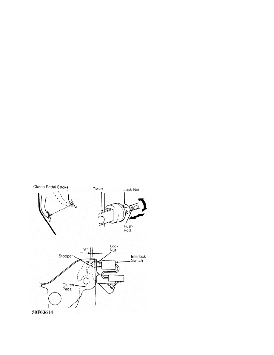
Fig. 1: Measuring Pedal Free Play & Height
Courtesy of Mitsubishi Motor Sales of America.
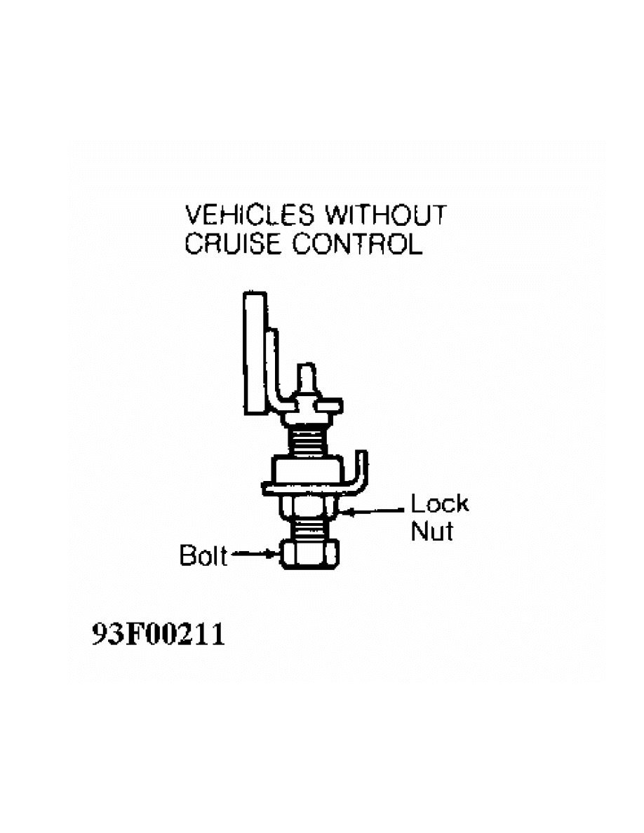
Fig. 2: Adjusting Lock Nut (Without Cruise Control)
Courtesy of Mitsubishi Motor Sales of America.
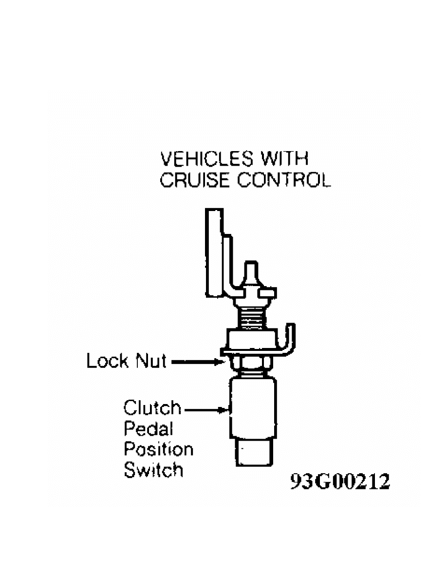
Fig. 3: Adjusting Lock Nut (With Cruise Control)
Courtesy of Mitsubishi Motor Sales of America.
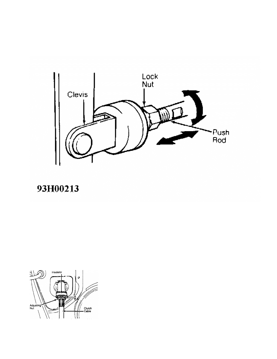
Fig. 4: Adjusting Push Rod
Courtesy of Mitsubishi Motor Sales of America.
2) Measure clutch pedal free play. See
CLUTCH PEDAL SPECIFICATIONS TABLE. See Figs. 1-4. If pedal free play
adjustment is necessary, pull clutch cable housing toward engine
compartment. Rotate cable adjusting nut until .12-.16" (3.0-4.0 mm)
clearance is obtained between adjusting nut and insulator holder. See
Fig. 5.
3) After making adjustments, depress pedal several times and
hold down. Measure distance between face of clutch pedal and floor
board. If depressed pedal height is less than specification, check
clutch components for damage and deformation. See
CLUTCH PEDAL SPECIFICATIONS TABLE.
Fig. 5: Adjusting Clutch Pedal Free Play (RWD)
Courtesy of Mitsubishi Motor Sales of America.
Pedal Adjustment (4WD)
1) To adjust pedal height, loosen lock nut and rotate pedal
stop bolt or switch at top of pedal assembly until correct pedal
height is obtained. Measure distance between face of clutch pedal and
floor board. See CLUTCH PEDAL SPECIFICATIONS TABLE.
See Figs. 1 to 4.
2) Measure clutch pedal free play. See Figs. 1-4. See CLUTCH
PEDAL SPECIFICATIONS TABLE. If pedal free play needs to be adjusted,
loosen lock nut on master cylinder push rod and rotate push rod to
obtain correct free play. See CLUTCH PEDAL SPECIFICATIONS TABLE.
Tighten lock nut. See Figs. 1-4.
3) After making adjustments, depress pedal several times and
hold down. Measure distance between face of clutch pedal and floor
board. If depressed pedal height is not as specified, bleed system and
inspect hydraulic and clutch components. See
CLUTCH PEDAL SPECIFICATIONS TABLE.
INTERLOCK SWITCH
Interlock Switch Adjustment
1) Check and adjust pedal height and free play. See
CLUTCH PEDAL HEIGHT & FREE PLAY. See Figs. 1-4. Measure clutch pedal
full stroke. Full stroke should be 5.72" (145 mm). If full stroke is
out of tolerance, adjust by turning push rod. See Fig. 6.
2) Measure clearance "A" with clutch pedal fully depressed
(full stroke). See Fig. 6. Clearance "A" should be .177-.217" (4.5-5.5
mm). If clearance is out of tolerance, adjust by loosening interlock
switch lock nut and turning interlock switch in appropriate direction.
When clearance "A" is correct, tighten lock nut to 115 INCH lbs. (13
N.m).
Fig. 6: Adjusting Interlock Switch
Courtesy of Mitsubishi Motor Sales of America.
REMOVAL & INSTALLATION
CLUTCH ASSEMBLY
Removal (4WD)
1) Remove switch panel from rear console. Remove suspension
control switch or hole cover. Disconnect rear console harness
connector. Remove side panel. Remove rear console assembly. Remove
shift lever knob(s). Remove floor console harness connector. Remove
front console assembly.
2) Move transmission lever to neutral position and transfer
lever to 4H (4WD high range) position on Montero or 2H (RWD high
range) on Pickup and Ram-50. Remove control lever boot retainer and
boot. Remove transmission and transfer control lever assemblies.
Remove control lever bushing (transmission), gaskets and stopper
plates.
3) Raise and support vehicle. Remove skid plate and front
exhaust pipe. Drain transmission and transfer case fluid. Index mark
front and rear drive shaft flanges. Remove front and rear drive
shafts.
4) Remove drive shaft dust seals. Disconnect HI/LO and
2WD/4WD detection switch connectors. Disconnect back-up light switch
connector. Disconnect center differential lock detection switch
connector. Disconnect center differential lock operation switch
connector. Disconnect 4WD operation detection switch. Disconnect
speedometer cable. Remove clutch slave cylinder heat shield. Remove
clutch slave cylinder (without disconnecting hydraulic line) and wire
aside. Remove starter and starter cover. Remove heat shield and both
transmission stays and then bellhousing lower cover.
5) Support transmission with transmission jack. Remove
transfer case roll stopper and bracket. Remove crossmember and engine
mounting rear insulator. Remove transfer case protector bracket and
mass damper. Remove remaining bell housing bolts. Pull toward rear of
vehicle to free transmission input shaft from clutch. Lower
transmission/transfer case from vehicle.
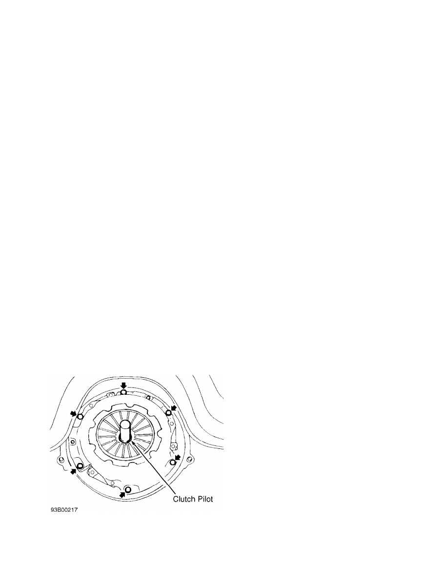
6) Insert a clutch pilot to prevent pressure plate and clutch
disc from dropping. Diagonally loosen pressure plate bolts to avoid
warping pressure plate flange during removal. Remove pressure plate
and clutch disc. See Fig. 7.
Fig. 7: Removing & Installing Clutch On Flywheel
Courtesy of Mitsubishi Motor Sales of America.
Inspection (4WD)
1) Check release bearing and release fork for damage or wear.
DO NOT clean bearing assembly in solvent. Inspect hydraulic system
components for fluid leakage. Inspect cylinder dust boot for cracks or
deterioration.
2) Inspect pressure plate surface for wear, cracks, and/or
discoloration. Check clutch disc rivets and replace assembly if loose.
Measure diaphragm spring ends for wear and uneven height. Replace
assembly if height difference between fingers exceeds .02" (.5 mm).
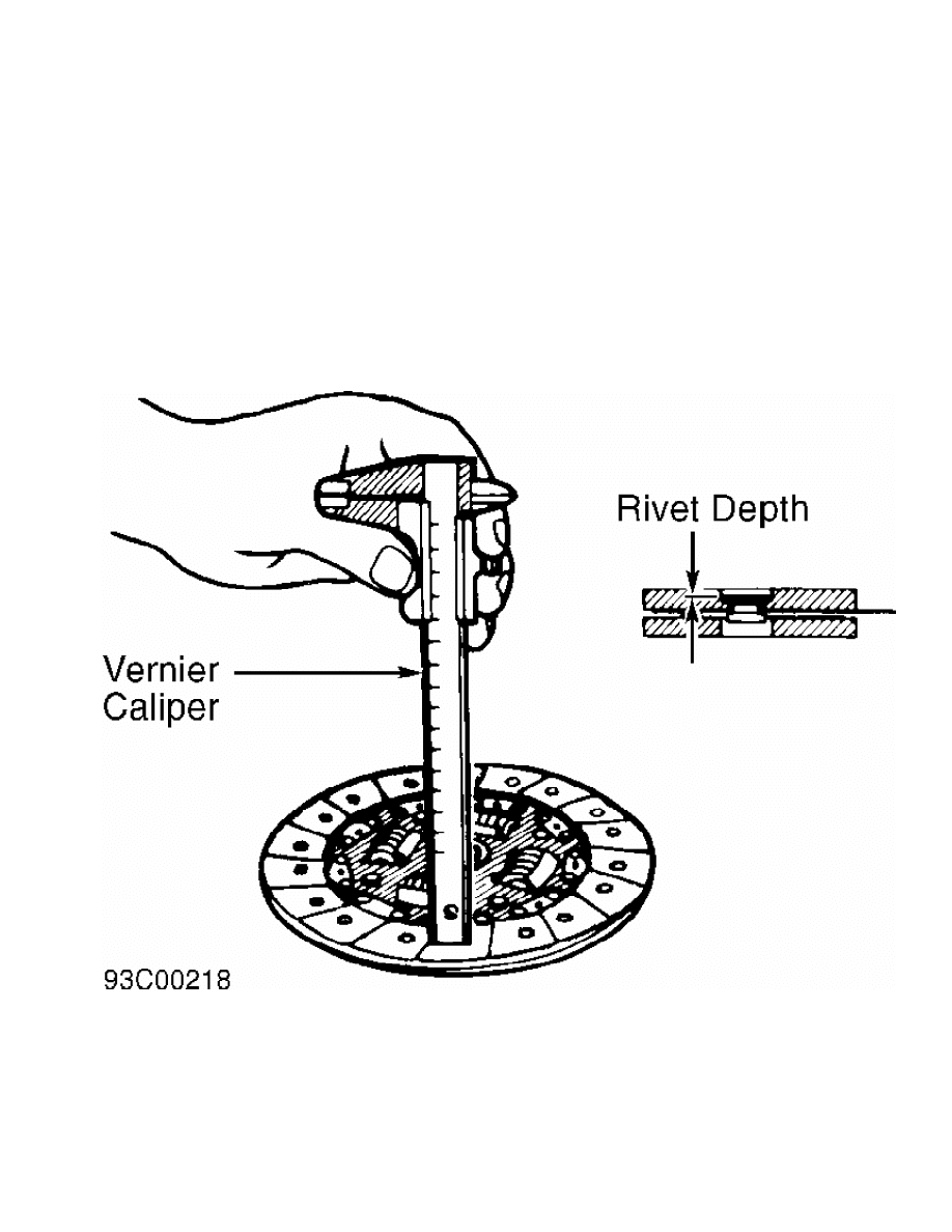
3) Check facing of clutch disc for loose rivets, uneven
contact, deterioration, seizure or oil saturation. Measure depth from
clutch disc surface to head of rivet. Replace clutch disc if
measurement is less than .012" (.30 mm). See Fig. 8. Replace worn or
defective components as necessary.
Fig. 8: Measuring Clutch Disc
Courtesy of Mitsubishi Motor Sales of America.
CAUTION: Install clutch disc with manufacturer’s stamp mark (located
near hub of clutch disc) toward pressure plate.
Installation (4WD)
1) Using clutch pilot, install pressure plate and clutch
disc. Tighten bolts evenly in a crisscross pattern to specification.
See TORQUE SPECIFICATIONS TABLE at the end of this article.
2) Clean release bearing sliding surface. Apply a light
coating of multipurpose grease to release bearing sliding surface.

Apply a very light coating of grease to input shaft splines. DO NOT
allow grease or dirt on clutch disc or pressure plate surfaces.
3) To install remaining components, reverse removal
procedure. Refill all fluids to proper levels. Adjust all control
cables, clutch pedal height and free play. See
CLUTCH PEDAL HEIGHT & FREE PLAY under ADJUSTMENTS. See Figs. 1-4.
Removal (RWD)
1) Disconnect battery negative cable. Remove shift knob, dust
cover retaining plate, gaskets, stopper plate and control lever
assembly. Raise and support vehicle.
2) Remove front exhaust pipe. drain transmission oil. Index
mark drive shaft flange and remove drive shaft.
3) Disconnect back-up light switch connector, speedometer
cable connection and exhaust pipe mounting bracket. Remove lower bell
housing cover. Disconnect clutch cable from clutch lever.
4) Support transmission with jack. Remove rear engine mount
nuts and bolts from transmission. Remove crossmember with rear engine
mount. Remove remaining bellhousing bolts, move transmission toward
rear and lower from vehicle.
5) Index mark pressure plate to flywheel for installation
reference. Install a clutch pilot to prevent pressure plate and clutch
disc from dropping. Diagonally loosen pressure plate bolts gradually
to avoid warping pressure plate flange during removal. Remove pressure
plate and clutch disc. See Fig. 7.
Inspection (RWD)
1) Check release bearing and release fork for damage or wear.
DO NOT clean bearing assembly in solvent.
2) Inspect pressure plate surface for wear, cracks, and/or
discoloration. Check clutch disc rivets and replace assembly if loose.
Measure diaphragm spring ends for wear and uneven height. Replace
assembly if height difference between fingers exceeds .02" (.5 mm).
3) Check facing of clutch disc for loose rivets, uneven
contact, deterioration, seizure or oil saturation. Measure distance
from clutch disc surface to head of rivet. Replace clutch disc if
distance is less than .012" (.30 mm). Replace worn or defective
components as necessary. See Fig. 8.
CAUTION: Install clutch disc with manufacturer’s stamp mark (located
near hub of clutch disc) toward pressure plate.
Installation (RWD)
1) Using clutch pilot, install pressure plate and clutch
disc. If reusing pressure plate, ensure index marks are aligned.
Tighten bolts evenly in a crisscross pattern to specification. See
TORQUE SPECIFICATIONS TABLE at the end of this article. See Fig. 7.
2) Clean release bearing sliding surface. DO NOT clean
release bearing with solvent. Apply a light coat of multipurpose
grease to release bearing sliding surface. Apply a very light coating
of grease to input shaft splines. DO NOT allow grease or dirt on
clutch disc or pressure plate surfaces.
3) To install remaining components, reverse removal
procedure. Refill all fluids to proper levels. Adjust all control
cables, clutch pedal height and free play. See
CLUTCH PEDAL HEIGHT & FREE PLAY under ADJUSTMENTS. See Figs. 1-4.
CLUTCH CABLE (RWD)
Removal
Pull lightly on clutch cable while loosening cable adjusting
wheel from inside engine compartment. Remove cable end from control
lever on transmission housing. Remove cable end from pedal lever.
Disconnect insulator from cable and remove cable.
Installation
Apply grease to contact areas between clutch pedal lever and
cable end, and release lever and cable end. Install insulator onto
cable end. Reverse removal procedure to complete installation. Adjust
clutch pedal free play. See CLUTCH PEDAL HEIGHT & FREE PLAY under
ADJUSTMENTS. See Figs. 1 and 2.
CLUTCH RELEASE BEARING & SHIFT ARM OR RELEASE FORK
Removal (RWD)
1) Remove transmission. See CLUTCH ASSEMBLY under REMOVAL &
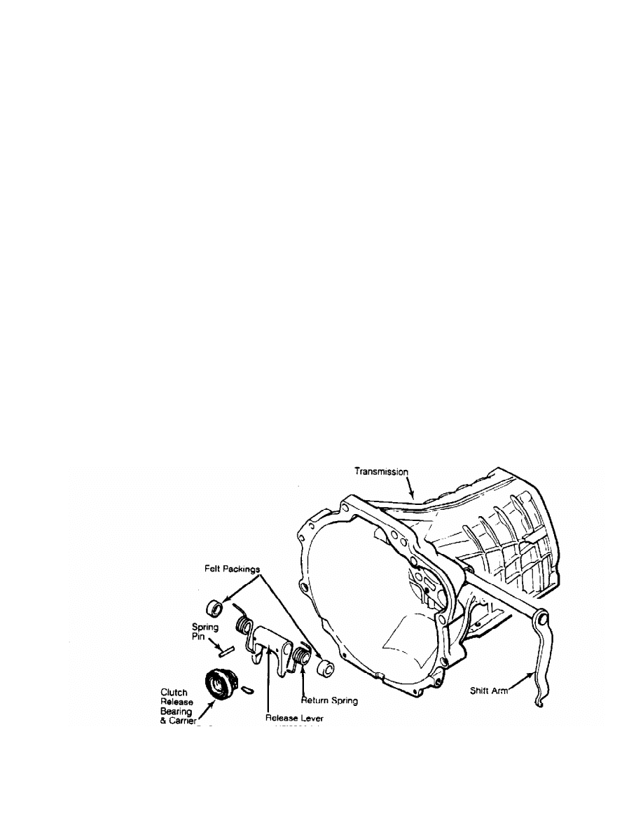
INSTALLATION. Remove return clips, release bearing and carrier. Use a
punch to remove shift arm spring pin and release lever assembly.
Remove shift arm, felt packing and 2 return springs. See Fig. 9.
2) Ensure release bearing turns freely and smoothly under
light load. Replace bearing if noise, roughness or dryness is present.
DO NOT clean bearing in solvent. Use shop towel or compressed air
only.
Installation (RWD)
1) Insert lever and shaft into left side of transmission
case. Place shift arm, felt packing and return springs on shaft
assembly. Apply grease to inside of bushing and oil seal lips. Apply
oil to felt packing.
2) Align shift arm pin and control shaft pin holes. Drive
spring pins into position, with slit area upward. Reverse removal
procedure to complete installation. Check pedal height and free play.
Adjust if necessary. See CLUTCH PEDAL HEIGHT & FREE PLAY under
ADJUSTMENTS.
Fig. 9: View Of Clutch Release Bearing & Shift Arm Assembly (RWD)
Courtesy of Mitsubishi Motor Sales of America.
Removal (4WD)
1) Remove transmission. See CLUTCH ASSEMBLY under REMOVAL &
INSTALLATION. Remove return spring or clips, and remove release
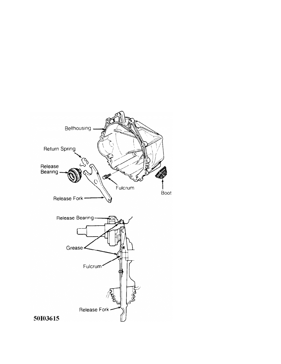
bearing.
2) Slide release fork toward outside of transmission and
disengage from fulcrum ball. DO NOT slide release fork toward inside
of case, or damage to fulcrum ball clip will result. Remove release
fork boot.
Installation (4WD)
To install, reverse removal procedure. Apply grease to
fulcrum ball contact area of release fork before installing. Fill
groove of release bearing inside diameter with grease before
installing. See Fig. 10.
Fig. 10: View Of Clutch Release Bearing & Shift Arm Assembly (4WD)
Courtesy of Mitsubishi Motor Sales of America.
CLUTCH MASTER CYLINDER (4WD)
Removal & Installation
1) Drain master cylinder. Remove cotter pin, washer and
clevis pin. Disconnect push rod from clutch pedal. Remove and plug
hydraulic line at clutch master cylinder.
2) Remove retaining nuts, clutch master cylinder and gasket.
To install, reverse removal procedure. Apply grease to clevis pin
before installing. Fill reservoir and bleed clutch system.
CLUTCH RELEASE CYLINDER (4WD)
Removal & Installation
Remove and plug hydraulic line at release cylinder. Remove
cylinder-to-transmission bolts. Remove clutch release cylinder. To
install, reverse removal procedure. Apply grease to push rod-to-
release fork contact area. Bleed clutch system.
OVERHAUL
CLUTCH MASTER CYLINDER (4WD)
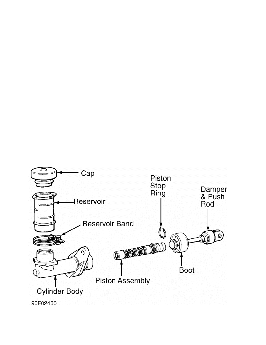
Disassembly
Remove piston stop ring, damper and push rod assembly. See
Fig. 11. Remove piston assembly. Note position of reservoir band for
reassembly reference. Remove reservoir.
Fig. 11: Exploded View Of Clutch Master Cylinder (Typical)
Courtesy of Mitsubishi Motor Sales of America.
Inspection & Reassembly
Inspect components for corrosion, scoring or damage. Replace
if necessary. Apply DOT 3 brake fluid to components during reassembly.
To reassemble, reverse disassembly procedure. Ensure piston moves
freely in bore.
CLUTCH RELEASE CYLINDER (4WD)
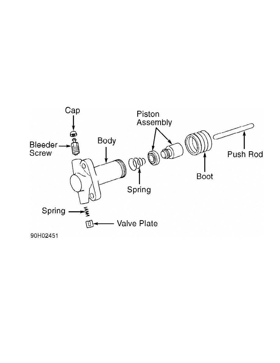
Disassembly
Remove valve plate and spring. See Fig. 12. Remove push rod
and boot. Cover piston assembly opening with a rag. Slowly apply air
pressure to hydraulic line opening to force piston from body.
Fig. 12: Exploded View Of Clutch Release Cylinder (Typical)
Courtesy of Mitsubishi Motor Sales of America.
Inspection & Reassembly
Inspect components for corrosion, scoring or damage. Replace
if necessary. Apply DOT 3 brake fluid to components during reassembly.
To reassemble, reverse disassembly procedure. Ensure piston moves
freely in bore.
TORQUE SPECIFICATIONS
TORQUE SPECIFICATIONS TABLE
Application Ft. Lbs. (N.m)
Flexhose-To-Release Cylinder Bolt .......... 14-18 (19-24)
Flywheel Bolt
2.4L Engines ........................... 94-101 (127-137)
3.0L Engines ............................. 53-55 (72-75)
Fulcrum Ball ............................... 22-30 (30-41)
Gearshift-To-Transfer Case Bolt ............ 11-15 (15-20)
Hydraulic Line-To-Master Cylinder .......... 10-12 (14-16)
Pressure Plate Bolt ........................ 11-15 (15-20)

Release Cylinder-To-Transmission Bolt ...... 22-30 (30-41)
Transmission-To-Engine Bolt
2.4L Engines
8 x 25 mm & 8 x 55 mm .................. 15-20 (20-27)
10 x 40 mm & 10 x 65 mm ................ 31-40 (42-54)
10 x 60 mm ............................. 20-25 (27-34)
3.0L Engines
10 x 35 mm ............................. 24-36 (33-49)
10 x 40 mm ............................. 22-30 (30-41)
10 x 55 mm ............................. 20-25 (27-34)
12 x 35 mm, 12 x 40 mm & 12 x 50 mm .... 47-61 (64-83)
12 x 55 mm ............................. 58-72 (79-98)
Wyszukiwarka
Podobne podstrony:
42 Clutch
1997 Clutch & V160
16 clutch system cable
42 Clutch
CLUTCH
07 Clutch
16 Electric Starter Starter Clutch
M35c Clutch
05 CLUTCH
15 clutch system hydaulic
Beaded Clutch
Group 006 Clutch
4 Clutch
16 Electric Starter Starter Clutch
clutchpursepattern
Diagonal Bobbles Clutch
11 Alternator Starter Clutch
CLUTCH
więcej podobnych podstron