
Service Source
K
Macintosh SE

Service Source
K
Basics
Macintosh SE
Basics
Overview - 1
Overview
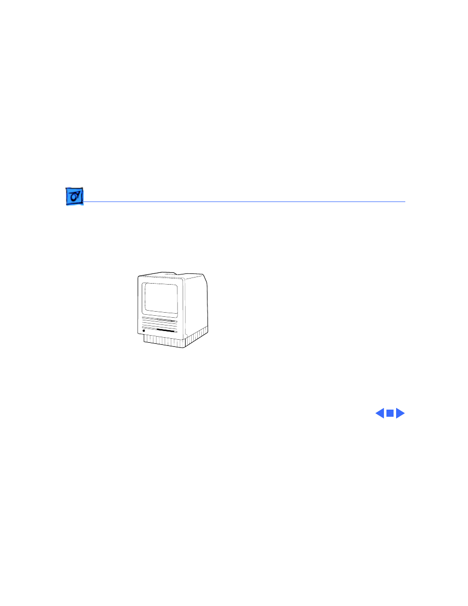
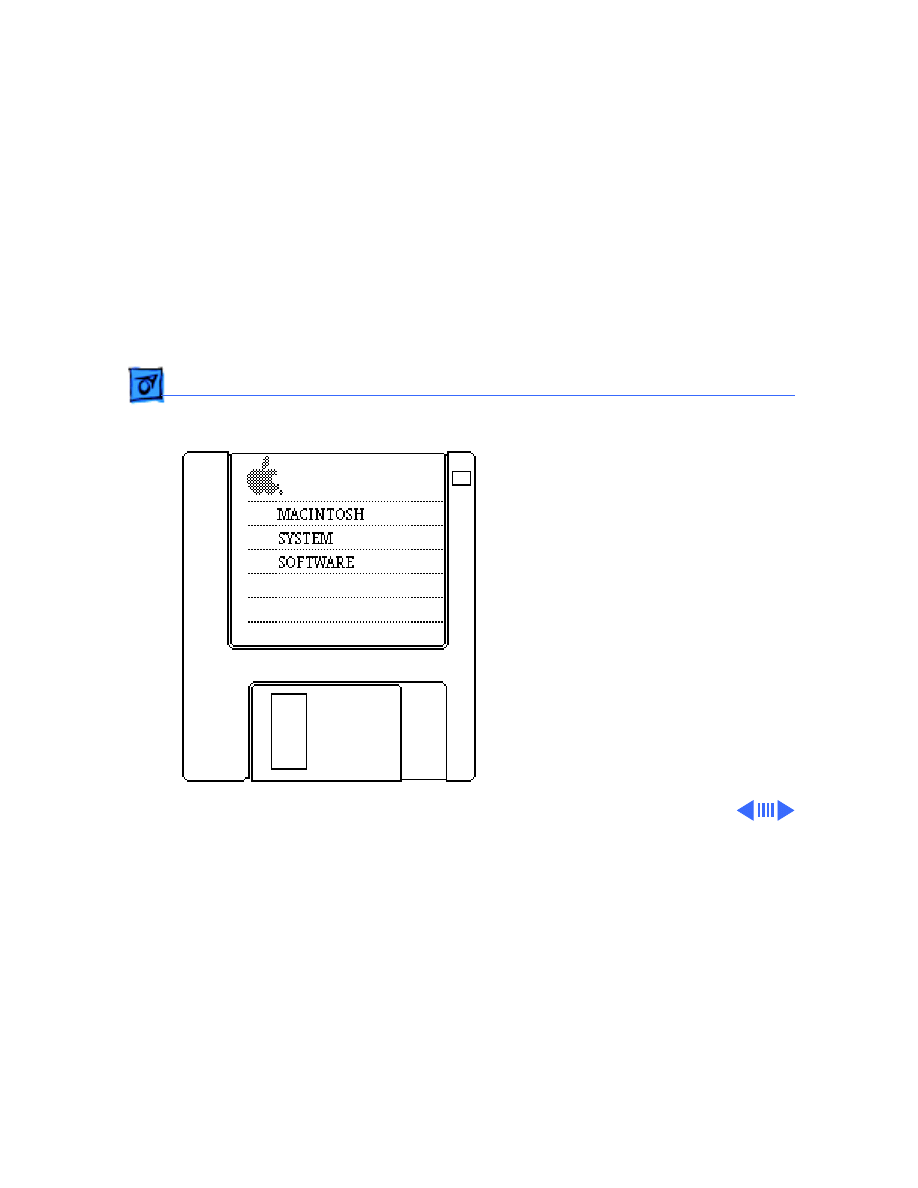
This manual contains
complete repair procedures
for the Macintosh SE, shown
at left.
Figure: Macintosh SE
Service Source
K
Specifications
Macintosh SE

Specifications
Processor - 1
Processor
CPU
Motorola 68000 microprocessor
7.83 MHz
32-bit architecture

Specifications
Memory - 2
Memory
RAM
1 or 2 MB, expandable to 4 MB
ROM
256K
PRAM
256 bytes of memory
CMOS custom chip with seven-year lithium battery

Specifications
Disk Storage - 3
Disk Storage
Floppy Drive
1.4 MB floppy drive
Optional second internal and external floppy drive
Hard Drive
Optional 20 or 40 MB hard drive
Optional external hard drive

Specifications
I/O Interfaces - 4
I/O Interfaces
Expansion
Macintosh SE expansion slot; uses a 96-pin Euro-DIN connector
SCSI
Uses a 50-pin connector (internal) and a DB-25 connector
(external)
Apple Desktop Bus
Two Apple Desktop Bus (ADB) connectors for communication with
keyboard, mouse, and other input devices
Serial
Two RS-232/RS-422 serial ports; 230.4 Kbaud maximum; mini
DIN-8 connectors
Sound
For external audio amplifier (standard miniature)

Specifications
I/O Devices - 5
I/O Devices
Keyboards
Apple Keyboard: 81 keys, including numeric keypad and cursor
keys
Apple Extended Keyboard: 105 keys, including 15 function keys,
separate cursor pad, and 10-key numeric keypad
Mouse
Mechanical tracking; optical shaft at 3.94 pulses per mm (100
pulses per in.) of travel; ADB connector
Specifications
Sound and Video - 6
Sound and Video
Sound Generator
Four-voice sound with 8-bit digital/analog conversion using 22-
kHz sampling rate
Video Display
9-in. (diagonal) screen; high-resolution, 512 by 342 pixel,
bit-mapped display

Specifications
Electrical - 7
Electrical
Line Voltage
90–140 VAC; 170–270 VAC
Frequency
47–63 Hz
Maximum Power
100 W

Specifications
Physical - 8
Physical
Dimensions
Height: 13.6 in. (34.5 cm)
Width: 9.6 in. (24.4 cm)
Depth: 10.9 in. (27.6 cm)
Weight
17–21 lb. (7.7–9.5 kg)
Weight varies depending on whether hard drive or second floppy
drive is installed

Service Source
K
Troubleshooting
Macintosh SE

Troubleshooting
General/ - 1
General
The Symptom Charts included in this chapter will help you
diagnose specific symptoms related to your product. Because cures
are listed on the charts in the order of most likely solution, try
the first cure first. Verify whether or not the product continues to
exhibit the symptom. If the symptom persists, try the next cure.
(Note: If you have replaced a module, reinstall the original module
before you proceed to the next cure.)
If you are not sure what the problem is, or if the Symptom Charts
do not resolve the problem, refer to the Flowchart for the product
family.
For additional assistance, contact Apple Technical Support.

Troubleshooting
Symptom Charts/Video - 2
Symptom Charts
Video
Screen is dark; audio
and drive operate
1 Turn brightness control clockwise.
2 Check video cable connections.
3 Replace analog board.
4 Replace video board.
5 Replace logic board. Retain customer’s SIMMs.
6 Replace CRT.
Screen is bright and
audio is present, but
no video information
is visible
1 Replace analog board.
2 Replace video board.
3 Replace logic board. Retain customer’s SIMMs.
Troubleshooting
Symptom Charts/Video
(Continued)
- 3
Video
(Continued)
Screen is completely
dark and fan is not
running
1 Replace power supply.
2 Replace analog board.
Single vertical line is
displayed
1 Replace analog board.
2 Replace video board.
3 Replace logic board. Retain customer’s SIMMs.
4 Replace CRT.
Single horizontal line
is displayed
1 Replace analog board.
2 Replace video board.
3 Replace logic board. Retain customer’s SIMMs.
4 Replace CRT.
Troubleshooting
Symptom Charts/Video
(Continued)
- 4
Video
(Continued)
Vertical bars or
stripes are displayed
1 Replace logic board. Retain customer’s SIMMs.
2 Replace analog board.
Horizontal bars or
stripes are displayed
1 Replace logic board. Retain customer’s SIMMs.
2 Replace analog board.
White dot is displayed
in center of screen
1 Verify that yoke cable is connected.
2 Replace analog board.
3 Replace CRT.
Screen jitters at top
left and/or lower
right
Replace analog board.

Troubleshooting
Symptom Charts/Peripheral - 5
Peripheral
Cursor does not move
1 Check mouse connection.
2 Inspect inside of mouse for buildup of dirt and other
contaminants. Clean mouse if necessary.
3 If mouse was connected to keyboard, connect it to ADB port
instead. If mouse works, replace keyboard.
4 If mouse does not work in any ADB port, replace mouse.
5 Replace logic board. Retain customer’s SIMMs.
Cursor moves, but
clicking mouse
button has no effect
1 Replace mouse.
2 Replace logic board. Retain customer’s SIMMs.
No response to any
key on keyboard
1 Check keyboard connection to ADB port.
2 Replace keyboard cable.
3 Replace keyboard.
4 Replace logic board. Retain customer’s SIMMs.

Troubleshooting
Symptom Charts/Peripheral
(Continued)
- 6
Peripheral
(Continued)
Cannot double-click
to open application,
disk, or server
1 Remove any multiple system files on hard drive.
2 Clear parameter RAM. (System 7: Hold down <Command>
<Option> <P> <R> during startup but before “Welcome to
Macintosh” appears. System 6: Hold down <Command>
<Option> <Shift> keys and select Control Panel from Apple
pull-down menu.) Reset mouse controls.
3 If mouse was connected to keyboard, connect it to ADB port
instead. If mouse works, replace keyboard.
4 If mouse does not work in any ADB port, replace mouse.
5 Replace logic board. Retain customer’s SIMMs.

Troubleshooting
Symptom Charts/Peripheral
(Continued)
- 7
Peripheral
(Continued)
Known-good
LaserWriter does not
1 Make sure that Chooser and Control Panel are set correctly.
2 Make sure correct version of system software is being used.
Make sure software is known-good.
3 Reset PRAM.
4 Refer to Networks and Communications manual.
Known-good
ImageWriter or
ImageWriter II does
not print
1 Make sure that Chooser and Control Panel are set correctly.
2 Make sure correct version of system software is being used.
Make sure software is known-good.
3 Reset PRAM.
4 Replace printer interface cable.
5 Replace logic board. Retain customer’s SIMMs.

Troubleshooting
Symptom Charts/Floppy Drive - 8
Floppy Drive
Audio and video are
present, but one
internal floppy drive
does not operate
1 Replace bad disk.
2 Replace floppy drive data cable.
3 Replace internal floppy drive.
4 Replace logic board. Retain customer’s SIMMs.
External floppy drive
does not operate
1 Replace bad disk.
2 Make sure external floppy drive is on right side of Macintosh
SE/30.
3 Replace external drive.
4 Replace logic board. Retain customer’s SIMMs.
Disk ejects; display
shows icon with
blinking “X”
1 Replace disk with known-good system disk.
2 Replace floppy drive.
3 Replace logic board. Retain customer’s SIMMs.

Troubleshooting
Symptom Charts/Floppy Drive
(Continued)
- 9
Floppy Drive
(Continued)
Unable to insert disk
all the way
1 Insert opened paper clip into hole beside drive.
2 Switch off system power and hold mouse button down while
switching power back on (to complete eject cycle).
3 Replace floppy drive.
Internal floppy drive
runs continuously
1 Replace bad disk.
2 Replace floppy drive.
3 Replace logic board. Retain customer’s SIMMs.
4 Replace floppy drive data cable.
Does not eject disk
1 Insert opened paper clip into hole beside drive.
2 Switch off system and hold mouse button down while
switching system back on (to complete eject cycle).
3 Replace floppy drive.

Troubleshooting
Symptom Charts/Floppy Drive
(Continued)
- 10
Floppy Drive
(Continued)
Audio and video are
present, but neither
internal floppy drive
operates
1 Replace bad disk.
2 Replace logic board. Retain customer’s SIMMs.

Troubleshooting
Symptom Charts/Hard Drive - 11
Hard Drive
Internal or external
hard drive does not
operate
1 Verify that SCSI loopback card is not attached.
2 Replace hard drive data cable.
3 Replace hard drive.
4 Replace logic board. Retain customer’s SIMMs.
Works with internal
or external SCSI
device but not with
both
1 Verify SCSI device switch setting on external device.
2 Replace terminator on external device.
3 Verify that terminator is installed on internal hard drive.
4 Replace hard drive select cable.

Troubleshooting
Symptom Charts/Miscellaneous - 12
Miscellaneous
Clicking, chirping,
or thumping sound
1 Verify analog board cable is connected at J12 on logic board.
2 Replace power supply.
3 Replace analog board.
4 Replace logic board. Retain customer’s SIMMs.
Smoke/odor
1 Replace power supply.
2 Replace analog board.
No video, no audio, and
no drive operation
1 Connect power cord.
2 Switch power on.
3 Replace power cord.
4 Replace power supply.
5 Replace analog board.
6 Replace logic board. Retain customer’s SIMMs.

Troubleshooting
Symptom Charts/Miscellaneous
(Continued)
- 13
Miscellaneous
(Continued)
“Sad Macintosh” icon
1 Replace bad disk.
2 Replace SIMM(s) if code matches any of those given in
“Isolating a Faulty SIMM” in Hardware/Memory.
3 Verify that three-pin jumper on logic board is configured
correctly for system RAM. See Hardware/Memory.
4 Replace logic board. Retain customer’s SIMMs.
“Sad Macintosh” icon
and black vertical
line are displayed;
screeching sound
1 Verify that three-pin jumper on logic board is configured
correctly for system RAM. See Hardware/Memory.
2 Replace logic board. Retain customer’s SIMMs.
Service Source
K
Take Apart
Macintosh SE
Take Apart
Cover - 1
Cover
No preliminary steps are
required before you begin
this procedure.
±
Warning:
This product
contains high voltage and a
high-vacuum picture tube.
To prevent serious injury,
review CRT safety in
Bulletins/Safety.
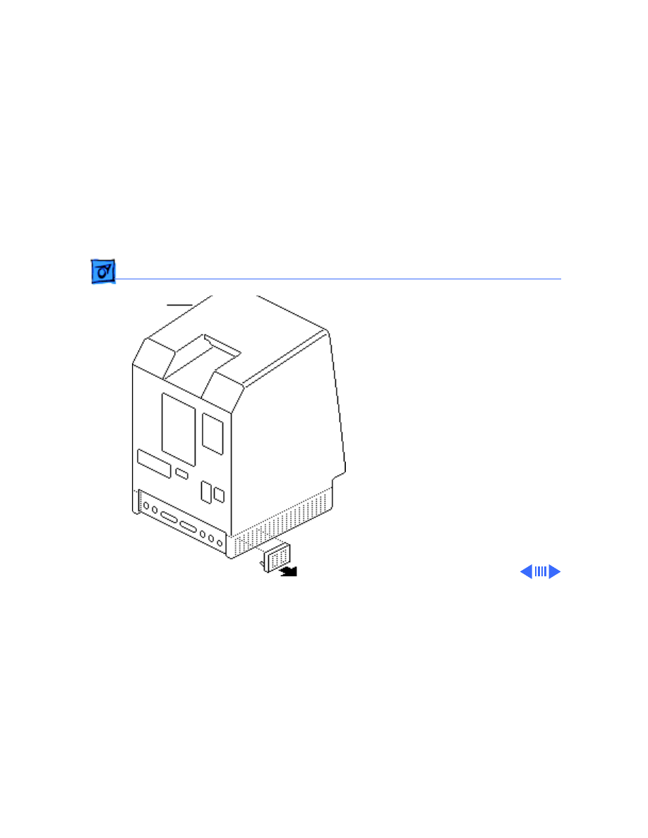
1 Using a small
screwdriver, pry off
the reset/interrupt
switch (if present).
Cover
Take Apart
Cover - 2
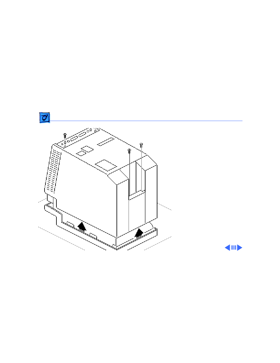
2 Using a Torx
screwdriver, remove
the four case screws and
separate the cover from
the chassis with a pull-
apart tool.
3 Carefully lift up the
cover and set it aside.
4 Remove the paper
insulating shroud from
the bottom of the
computer.

Take Apart
Cover - 3
Replacement Note:
Reinstall the two black case
screws in the bottom of the
cover and the two silver-
colored case screws in the
top of the cover.
Take Apart
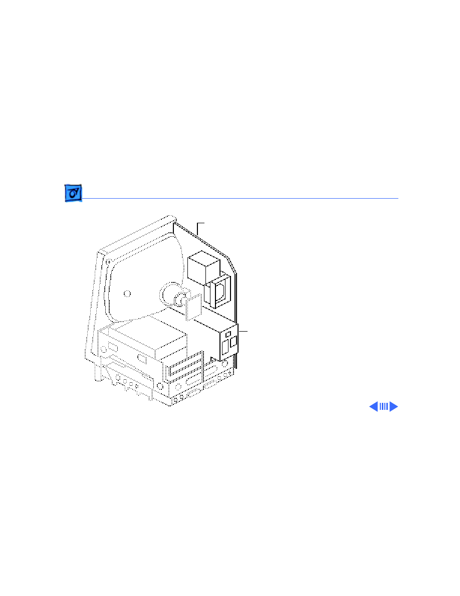
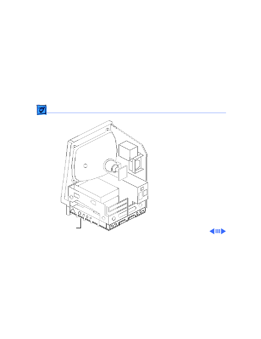
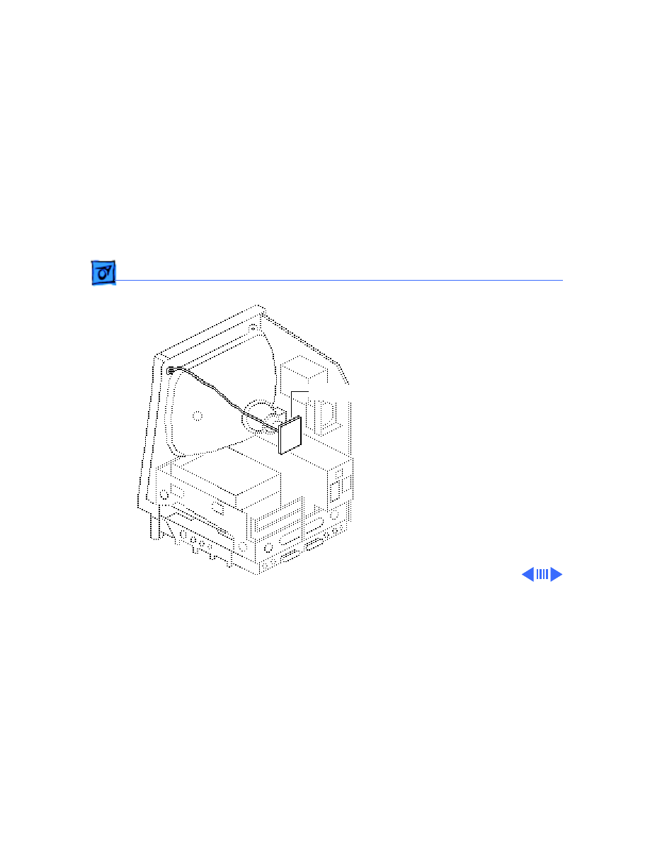
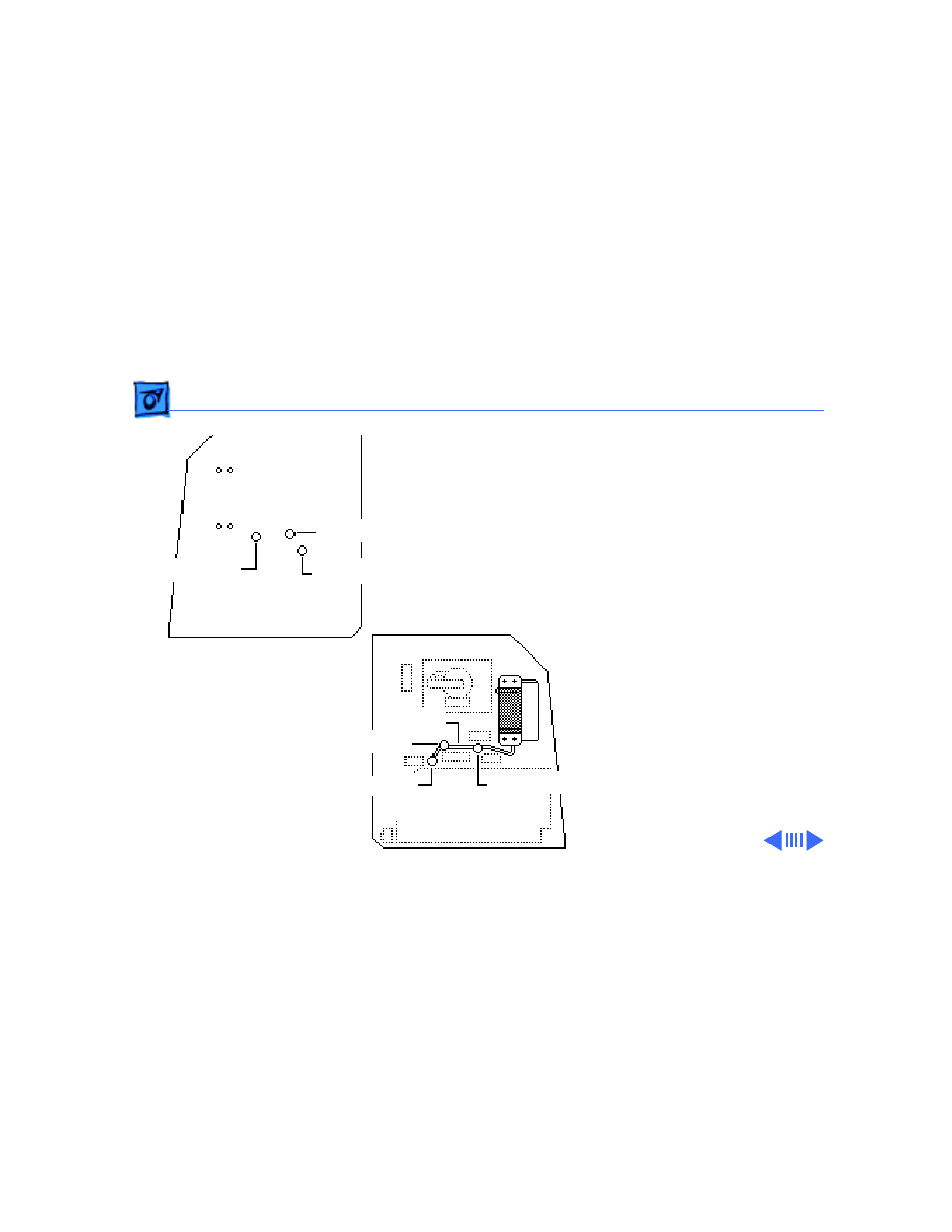
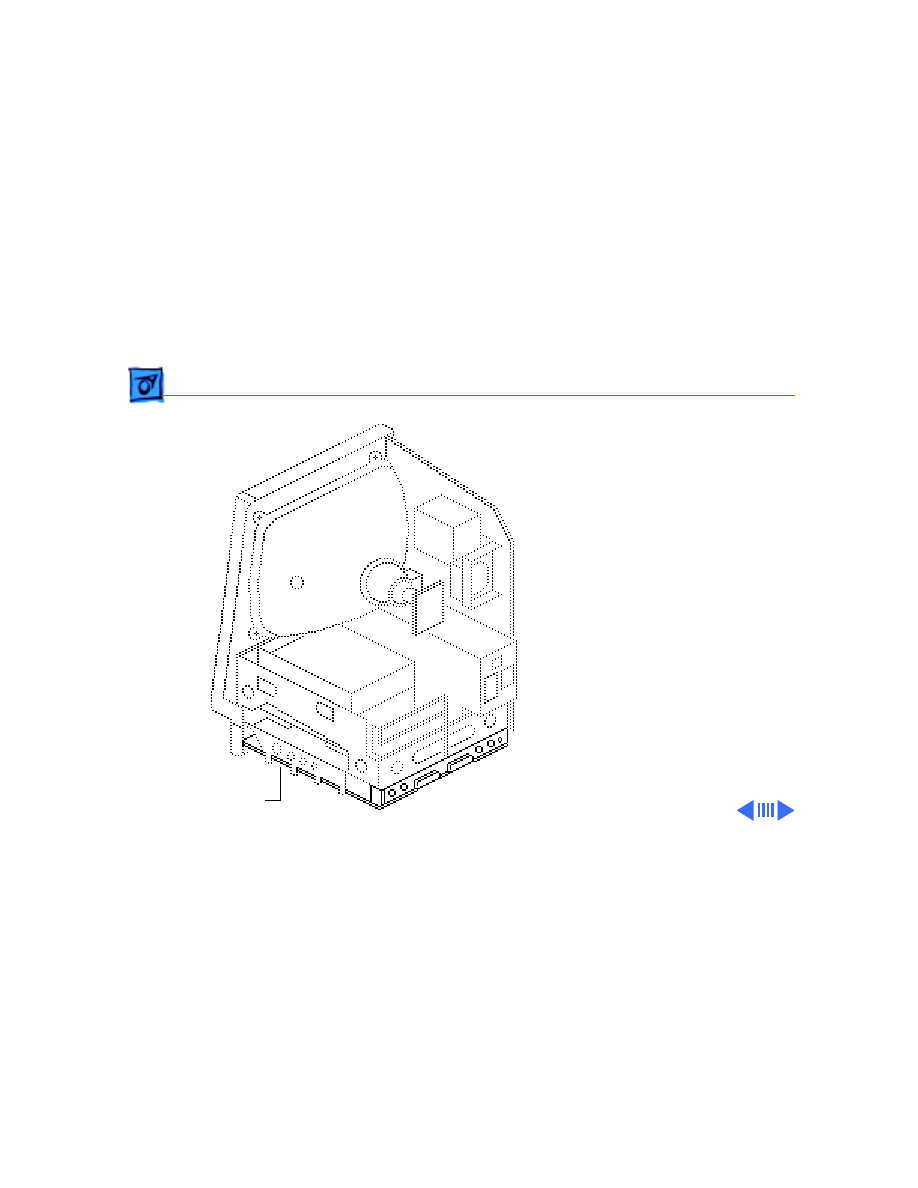
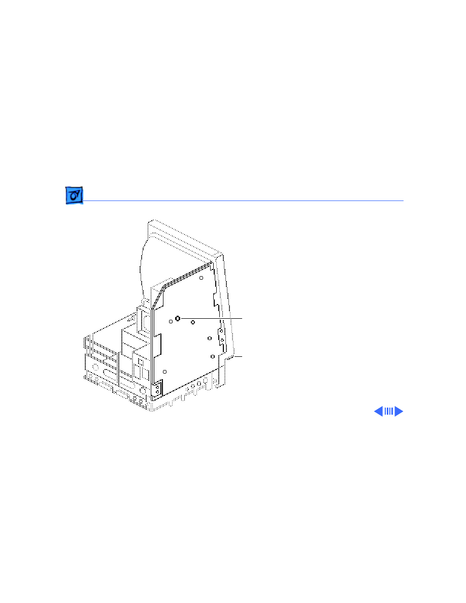
Analog Board & Power Supply - 4
Analog Board &
Power Supply
Before you begin,
• Remove the cover
• Discharge the CRT
• Remove the anode cap
Caution:
Be sure to
discharge the CRT to the
ground lug. Failure to do so
could damage the logic board
or the analog board.
Caution:
Never use a
grounding wriststrap until
after discharging the CRT.
Analog Board
Power
Supply
Take Apart
Analog Board & Power Supply - 5
1 Carefully pull the video
board straight off the
neck of the CRT.
2 Remove the screw that
secures the power
supply ground wire to
the chassis.
Video Board
Ground Wire
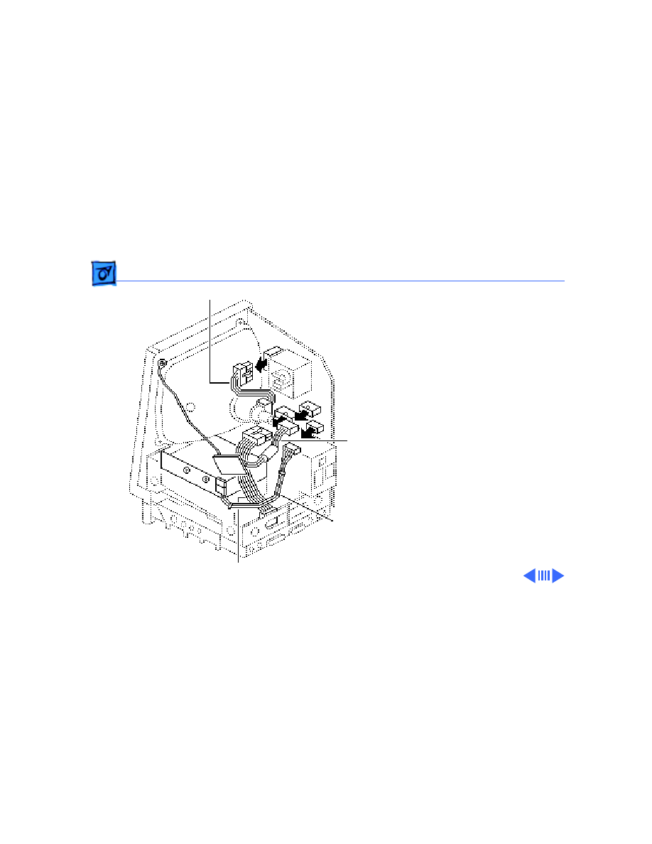
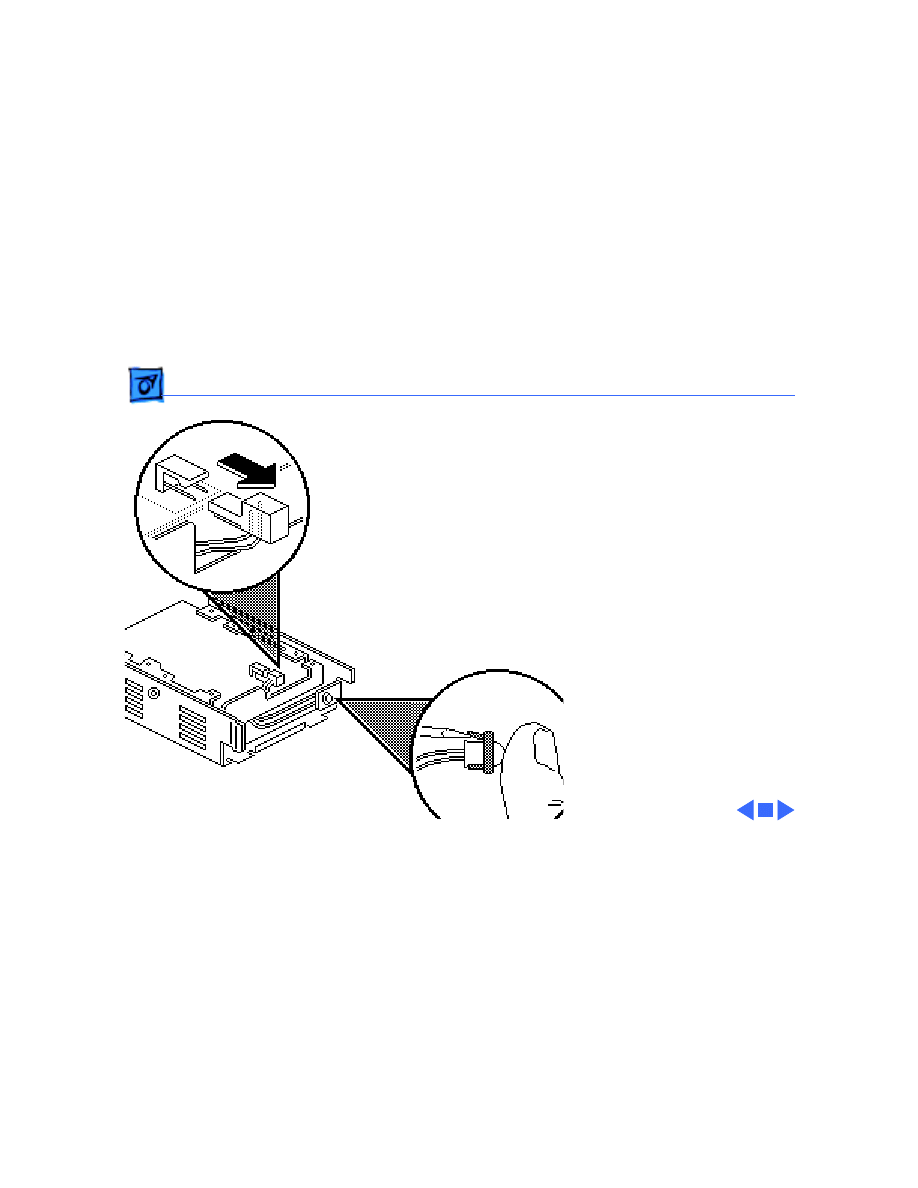
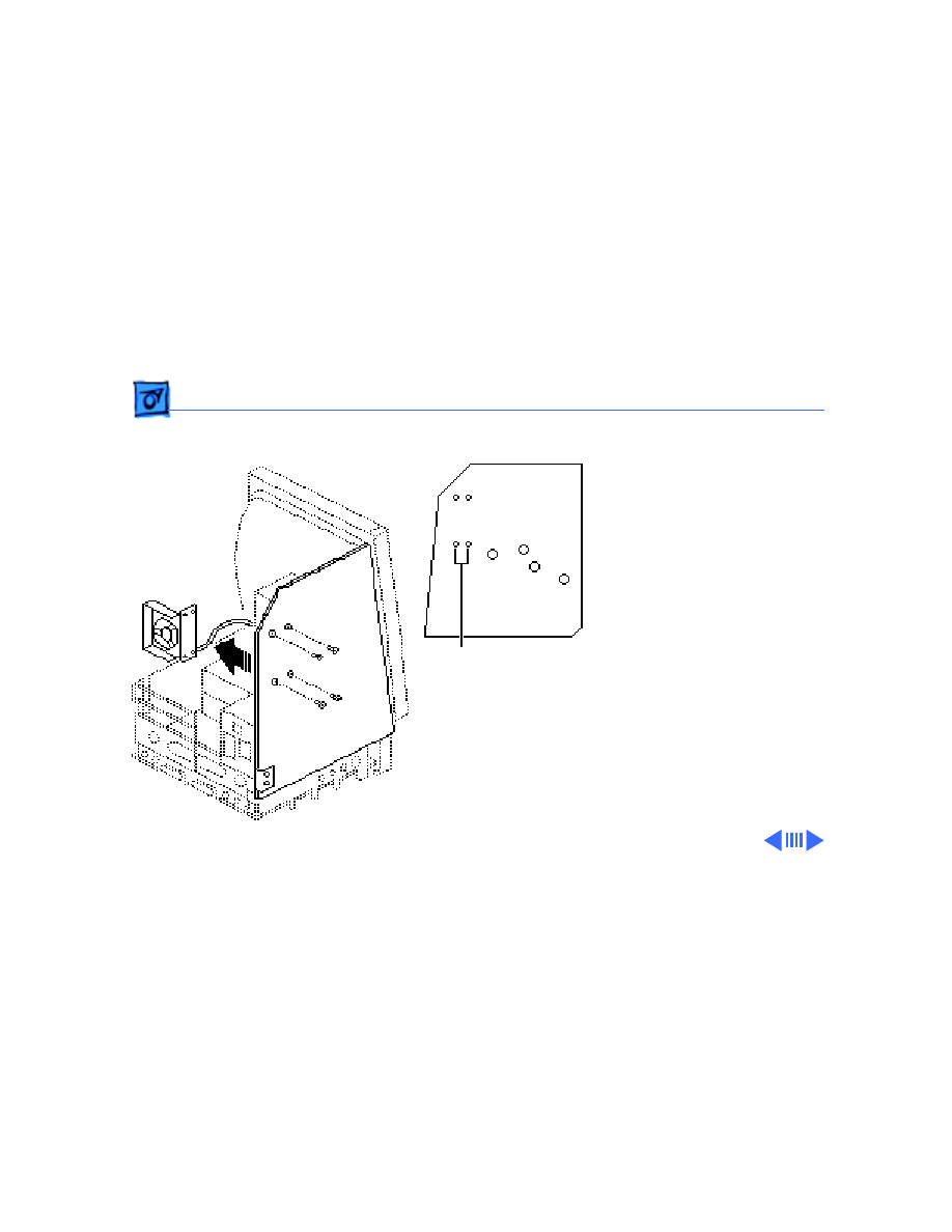
Take Apart
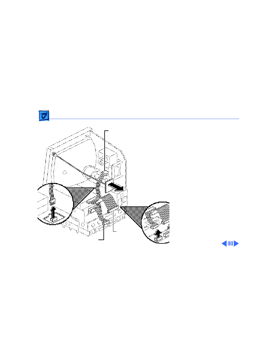
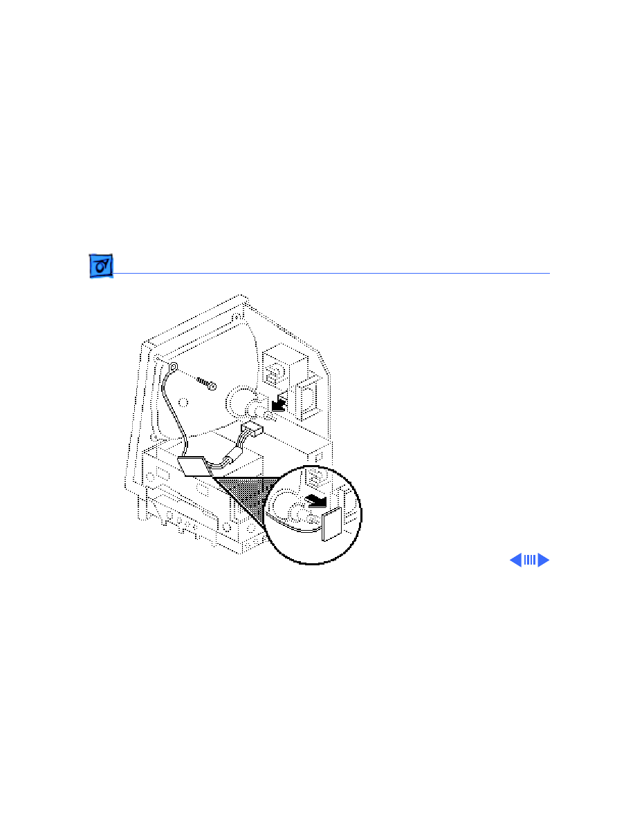
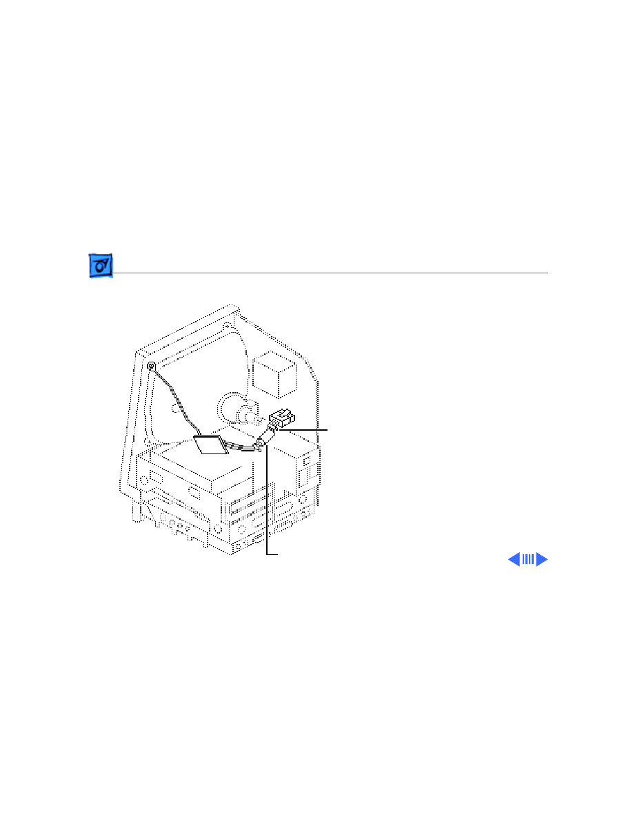
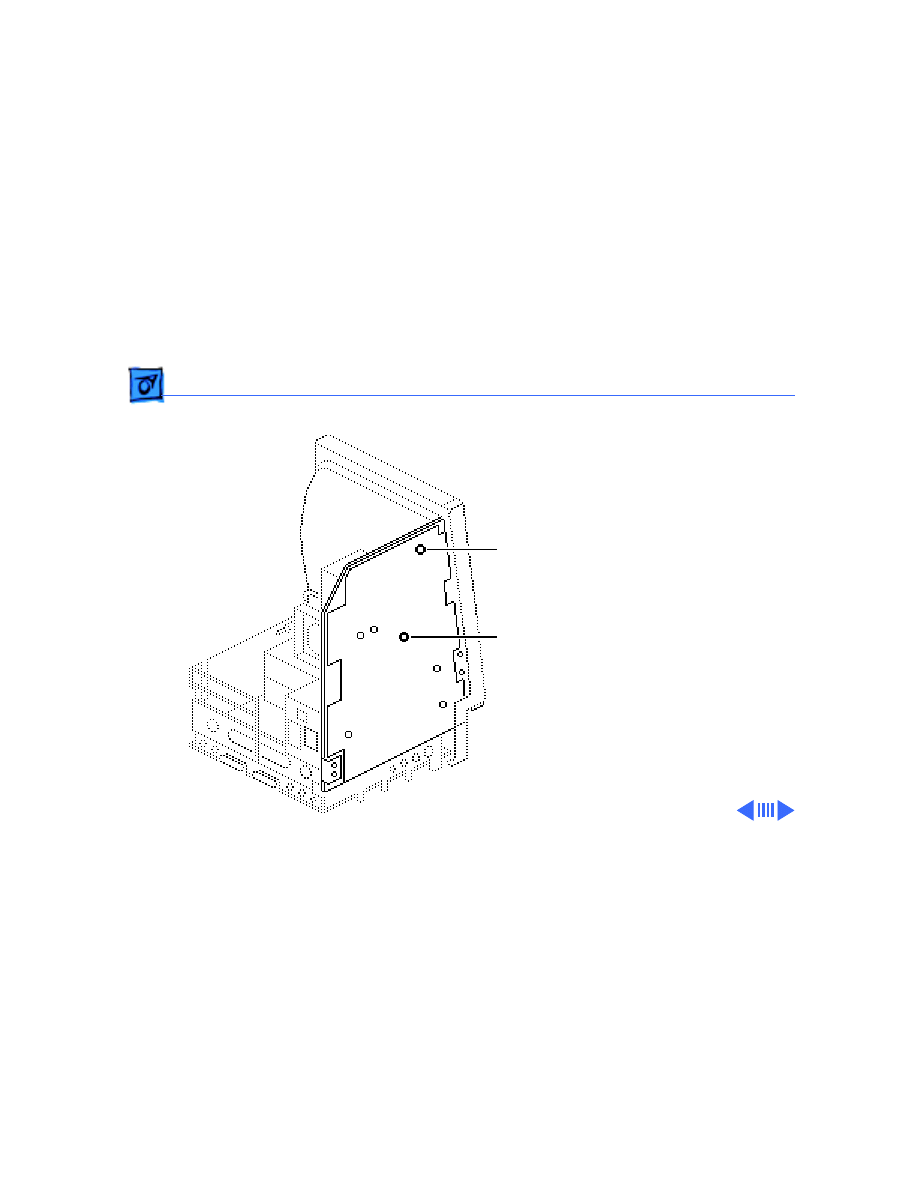
Analog Board & Power Supply - 6
3 Disconnect these cable
connectors from the
analog board:
• Yoke cable (First
depress the tab.)
• Logic board cable
• Video board cable
• Hard drive power
cable
Logic Board Cable
Power Cable
Hard Drive
Video
Board
Cable
Yoke Cable
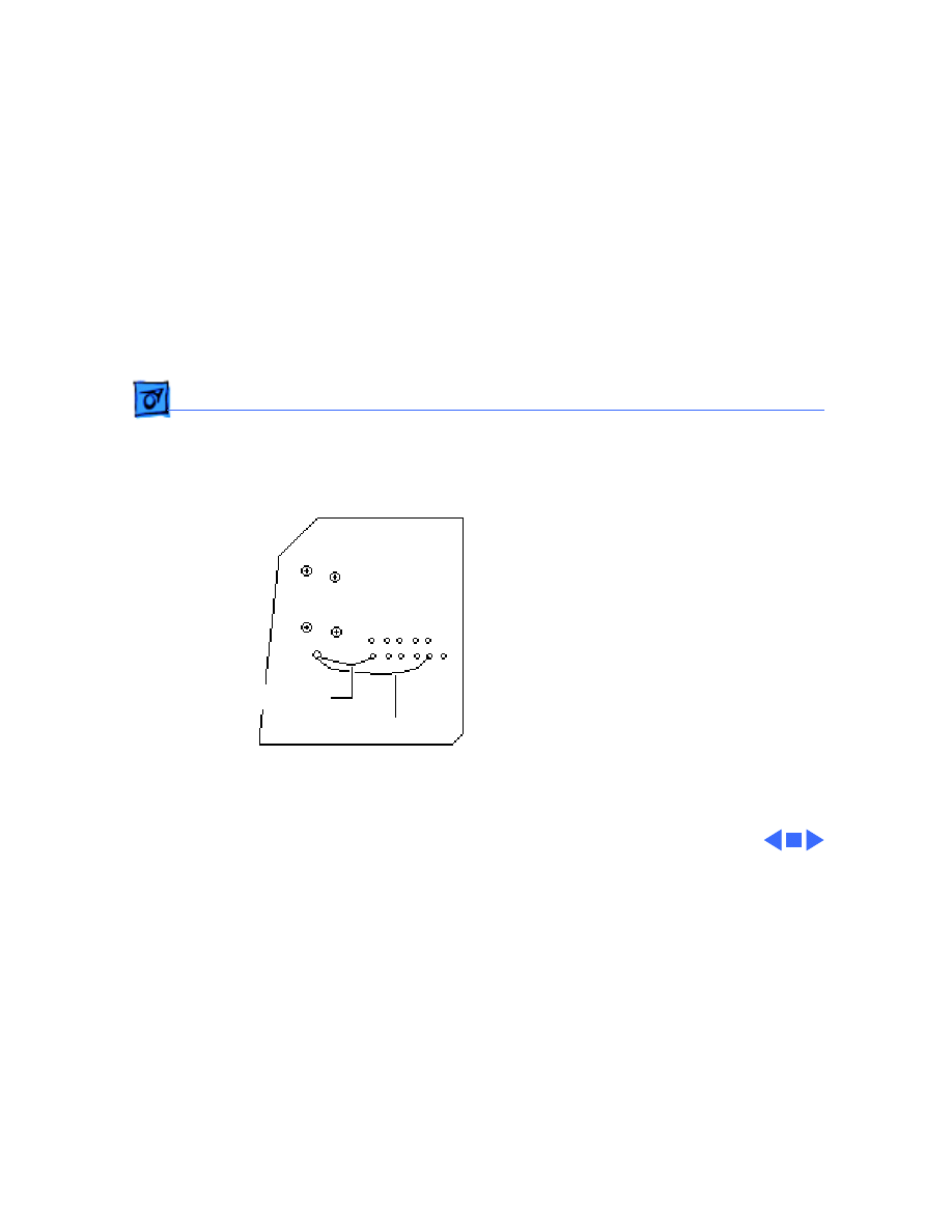
Take Apart
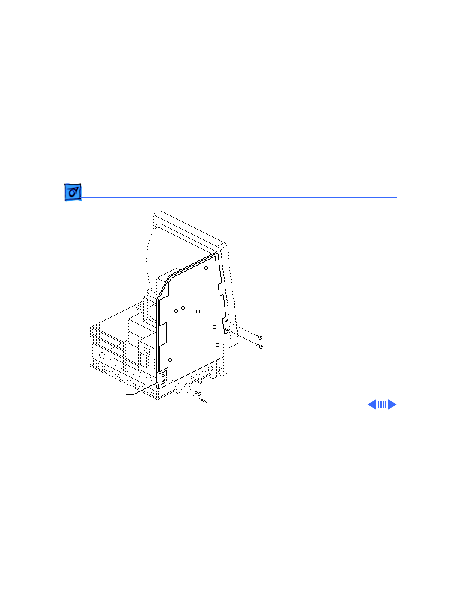
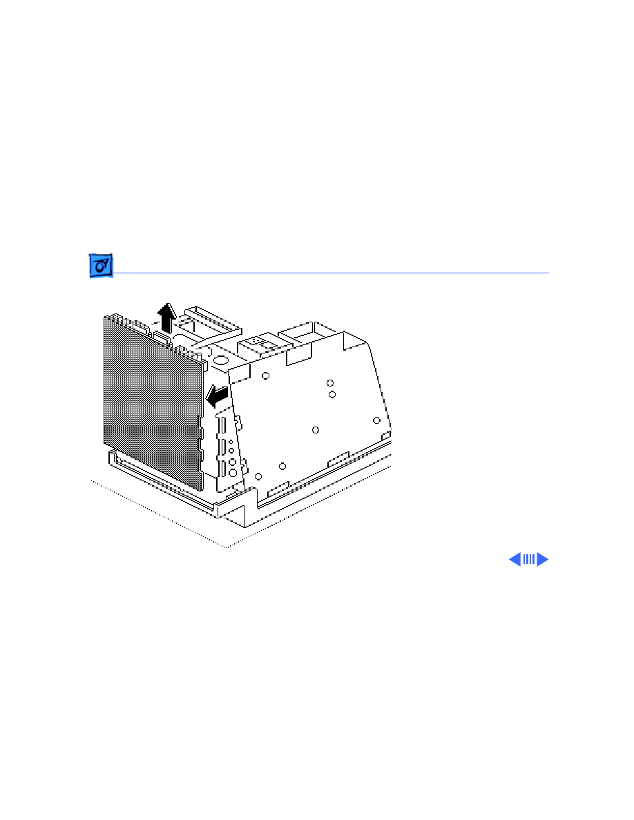
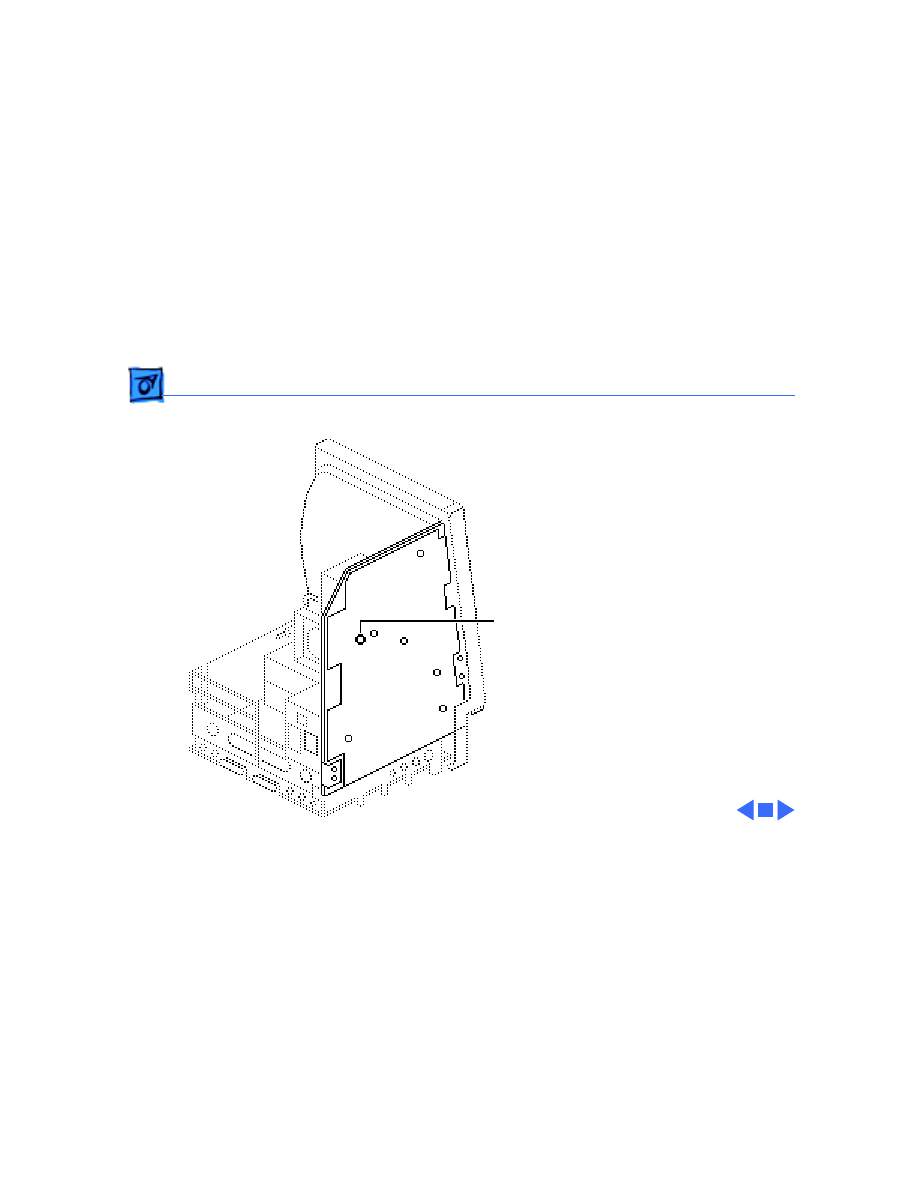
Analog Board & Power Supply - 7
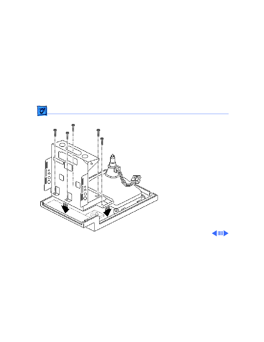
4 Remove the four screws
that secure the analog
board to the chassis.
5 Remove the metal clip
from the corner of the
board.
Metal Clip
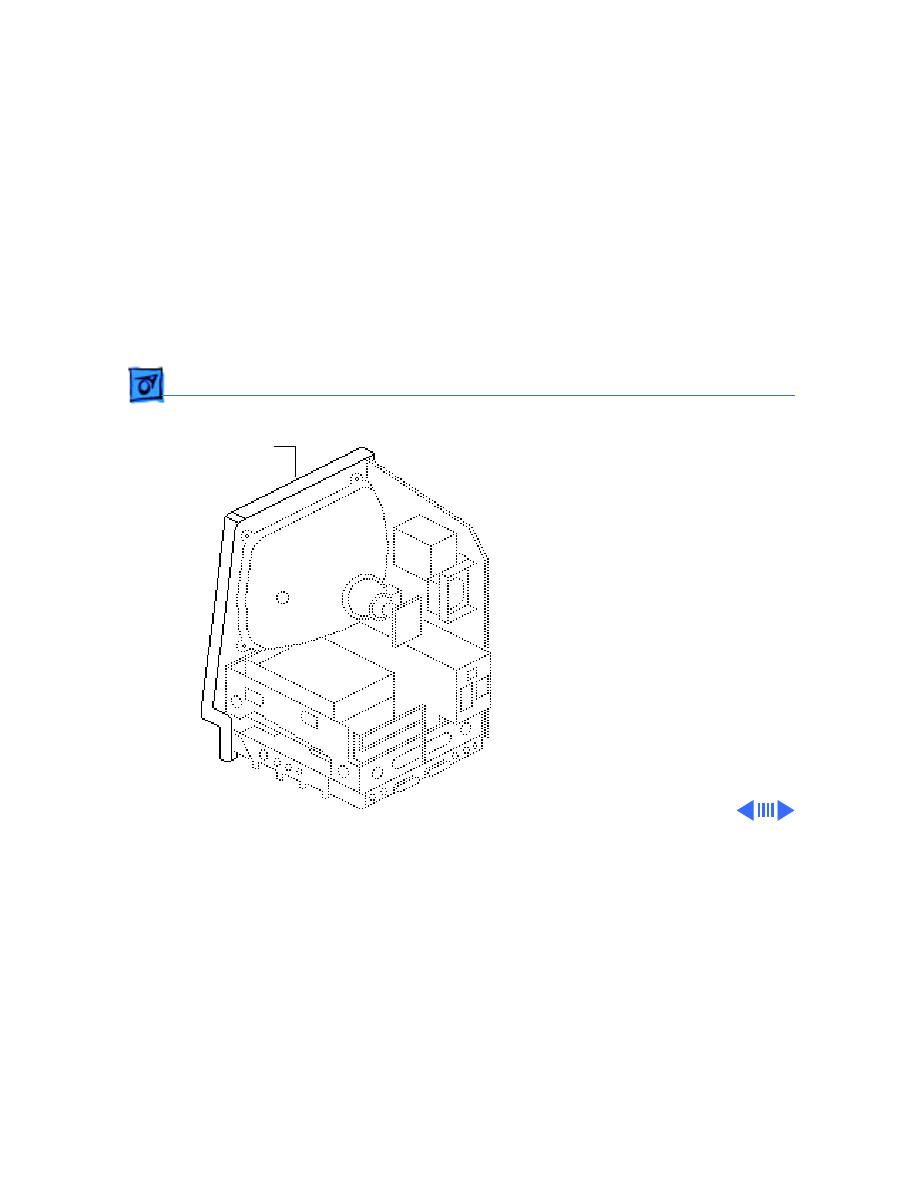
Take Apart
Analog Board & Power Supply - 8
6
Caution:
When
removing the analog
board, be careful not to
catch the brightness
control knob on the
chassis and not to bump
the neck of the CRT.
Grasp the analog board
by its edges and pull the
board up and out of the
chassis.
Take Apart
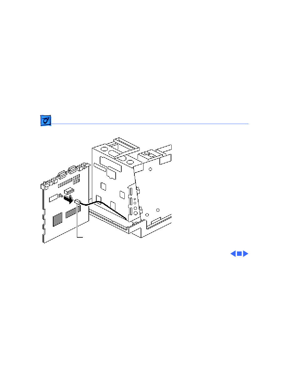
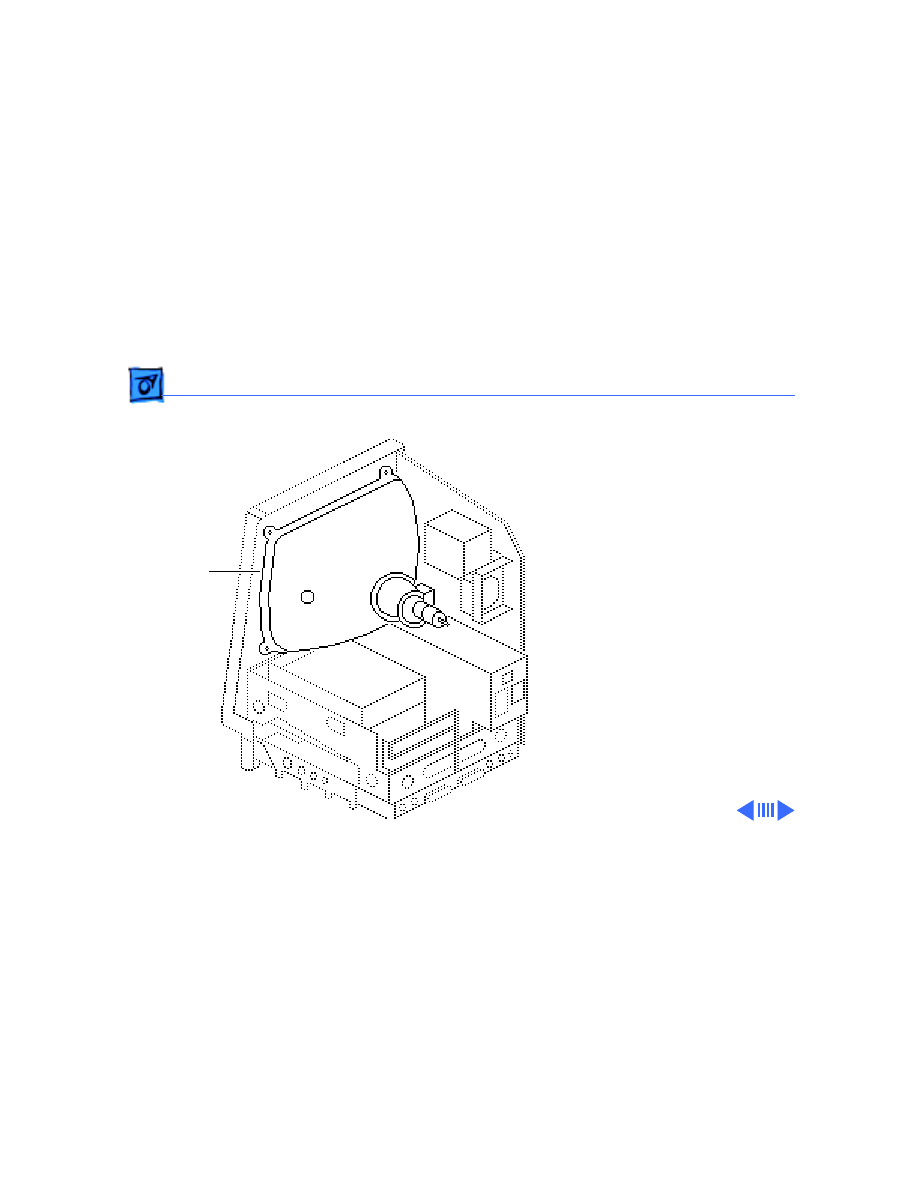
Analog Board & Power Supply - 9
7 Place the analog board on
a protective pad and
disconnect the power
supply cable.
Power Supply
Cable
Take Apart
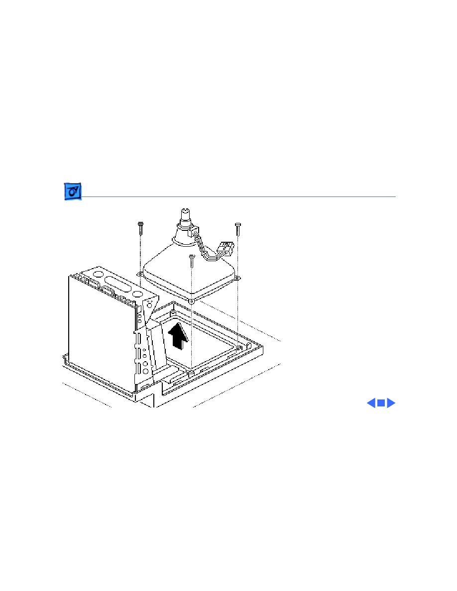
Analog Board & Power Supply - 10
8 Remove the four screws
and separate the power
supply from the analog
board.
Replacement Note:
If you
are replacing a defective
analog board, remove and
keep the brightness control
knob.
Brightness
Control Knob
Take Apart
Analog Board & Power Supply - 11
Replacement Note:
If you
receive a replacement analog
board that is packaged with a
ferrite bead, and if the
customer’s video cable does
not have a ferrite bead
attached, install the
packaged ferrite bead on the
video cable as shown.
Secure the ferrite bead to
the cable with a tie-wrap.
Replacement Note:
If you
replace the analog or power
supply, perform the video
adjustment procedure. See
“Video” in Adjustments.
Ferrite Bead
Take Apart
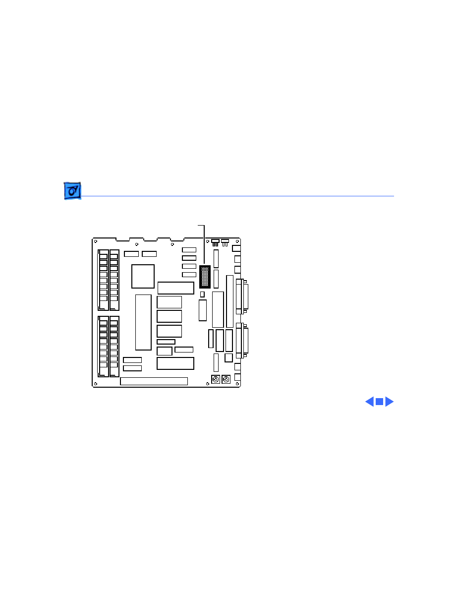
Logic Board - 12
Logic Board
Before you begin,
• Remove the cover
• Discharge the CRT
Caution:
Be sure to
discharge the CRT to the
ground lug. Failure to do so
could damage the logic board
or the analog board.
Warning: Never use a
grounding wriststrap until
after discharging the CRT.
Logic Board
Take Apart
Logic Board - 13
1 Carefully pull the video
board straight off the
neck of the CRT.
2 Disconnect these cable
connectors from the
logic board:
• Hard drive data cable
(if present)
• Internal floppy drive
cable(s)
• Power supply cable
Note:
You must first
depress the holding clip
to remove the power
supply cable.
Power Supply Cable
Floppy Drive Cable
Hard Drive
Data Cable
Take Apart
Logic Board - 14
3 Slide up the logic board
until its tabs are aligned
with the notches in the
chassis. Swing out the
right side of the board
and remove it from the
chassis.
Take Apart
Logic Board - 15
4 Disconnect the speaker
cable from the logic
board.
Replacement Note:
If you
are replacing a defective
logic board, you must use an
exchange logic board that is
configured the same as the
customer’s original board.
See “Identifying SE Logic
Boards” in the Additional
Procedures chapter for
more information.
Speaker Cable
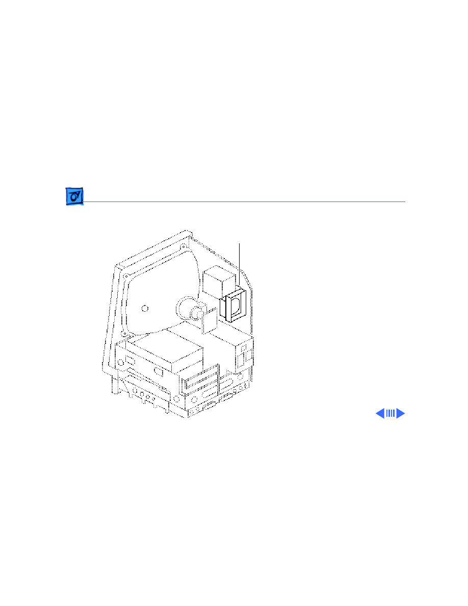
Take Apart
Video Board - 16
Video Board
Before you begin,
• Remove the cover
• Discharge the CRT
Caution:
Be sure to
discharge the CRT to the
ground lug. Failure to do so
could damage the logic board
or the analog board.
Warning:
Never use a
grounding wriststrap until
after discharging the CRT.
Video Board
Take Apart
Video Board - 17
1 Carefully pull the video
board straight off the
neck of the CRT.
2 Disconnect the video
board connector from the
analog board.
3 Remove the Torx screw
and video ground wire
from the upper-left
CRT mounting bracket.
Replacement Note:
If you
replace the video board,
perform the video
adjustment procedure. See
“Video” in Adjustments.

Take Apart
Video Board - 18
Replacement Note:
Replacement video boards
are installed vertically on
the CRT. The vertically-
mounted video board
requires using the axial
(round) fan.
Take Apart
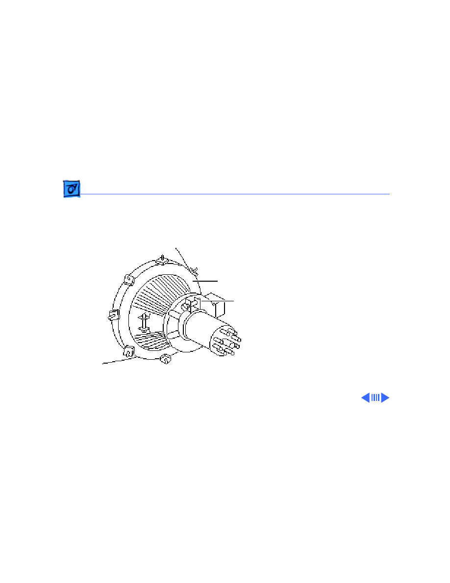
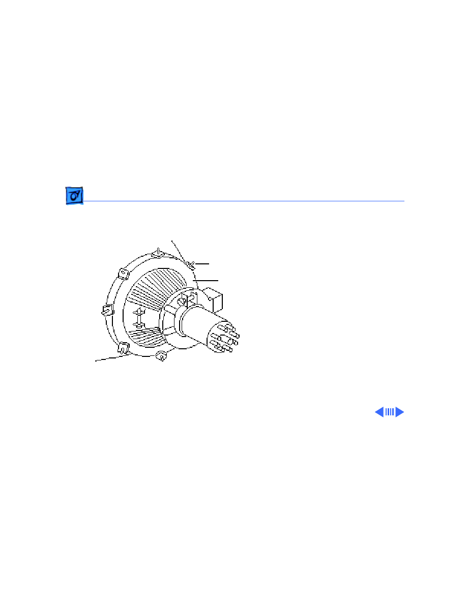
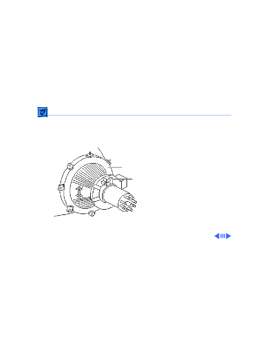
CRT - 19
CRT
Before you begin,
• Remove the cover
• Discharge the CRT
• Remove the anode cap
• Remove the video board
• Remove the analog board
(only)
CRT
Take Apart
CRT - 20
1 With the CRT face-down
on a protective pad, use a
Torx screwdriver to
remove the three
remaining CRT
mounting screws.
2 Lift the CRT off the
bezel.
Replacement Note:
If you
replace the CRT, perform
the video and yoke
adjustment procedures. See
“Video” and “Yoke” in the
Adjustments chapter.
Take Apart
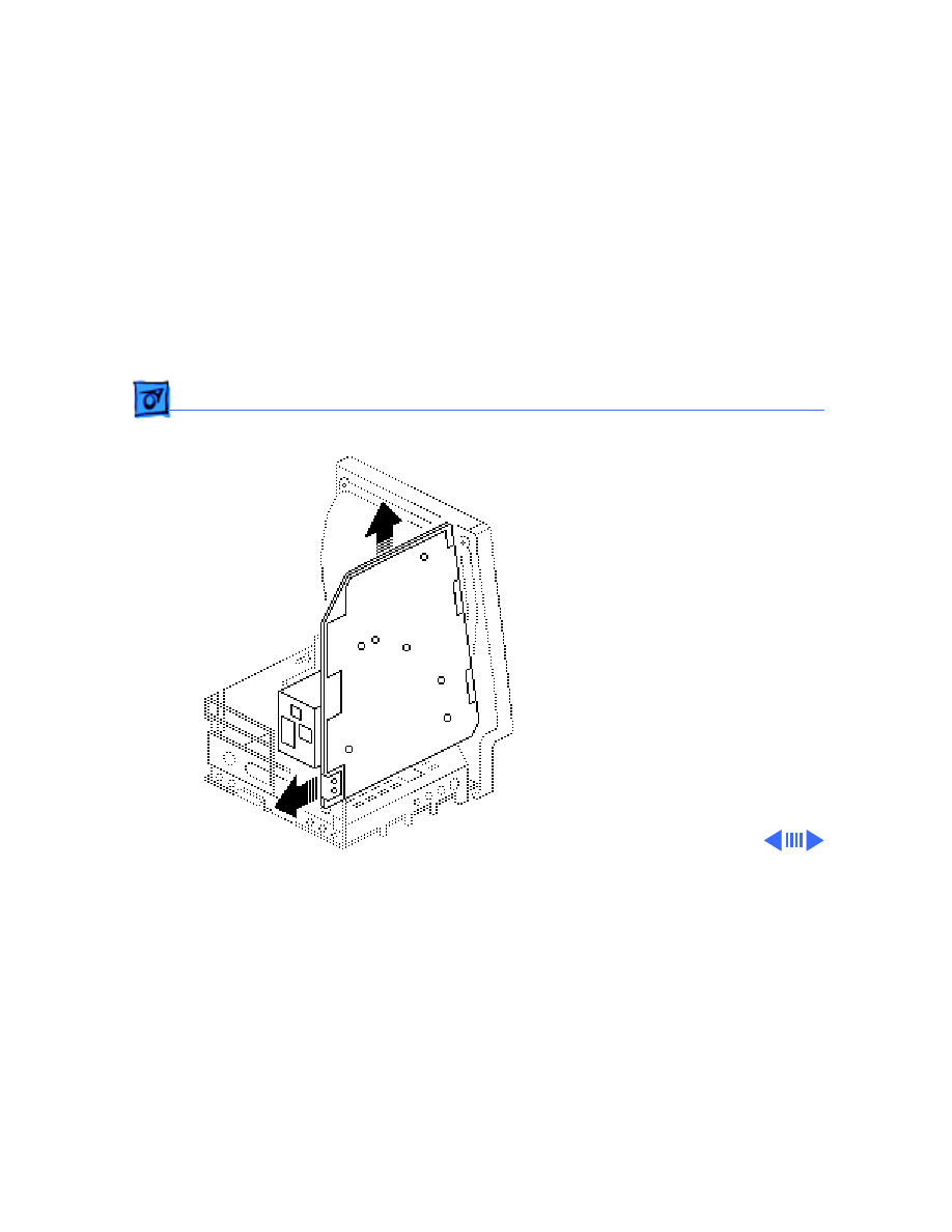
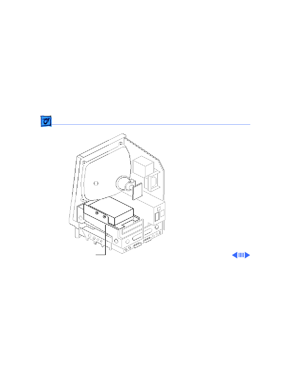
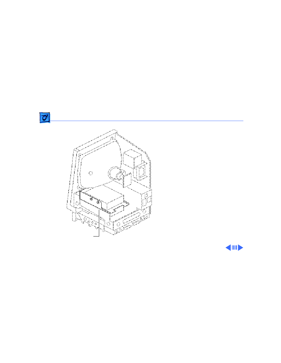
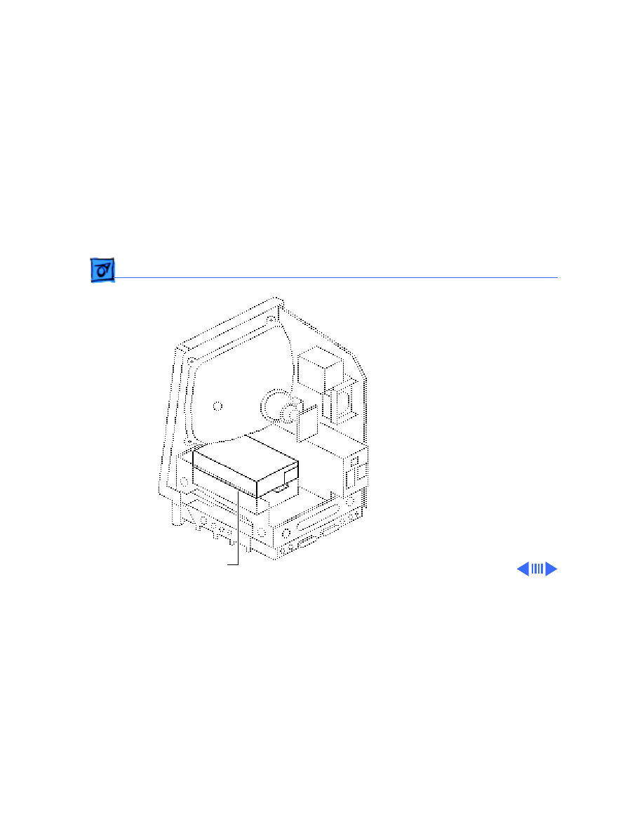
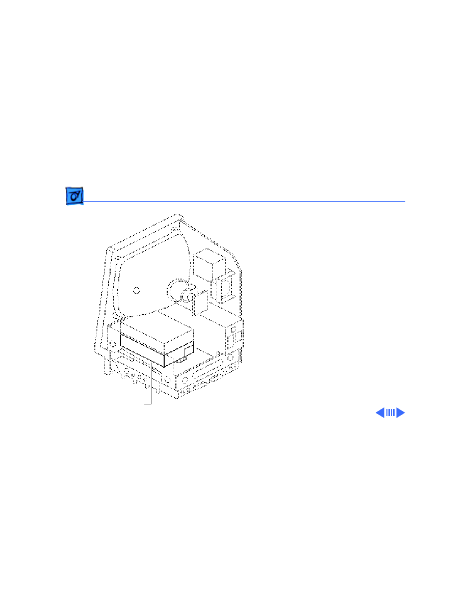
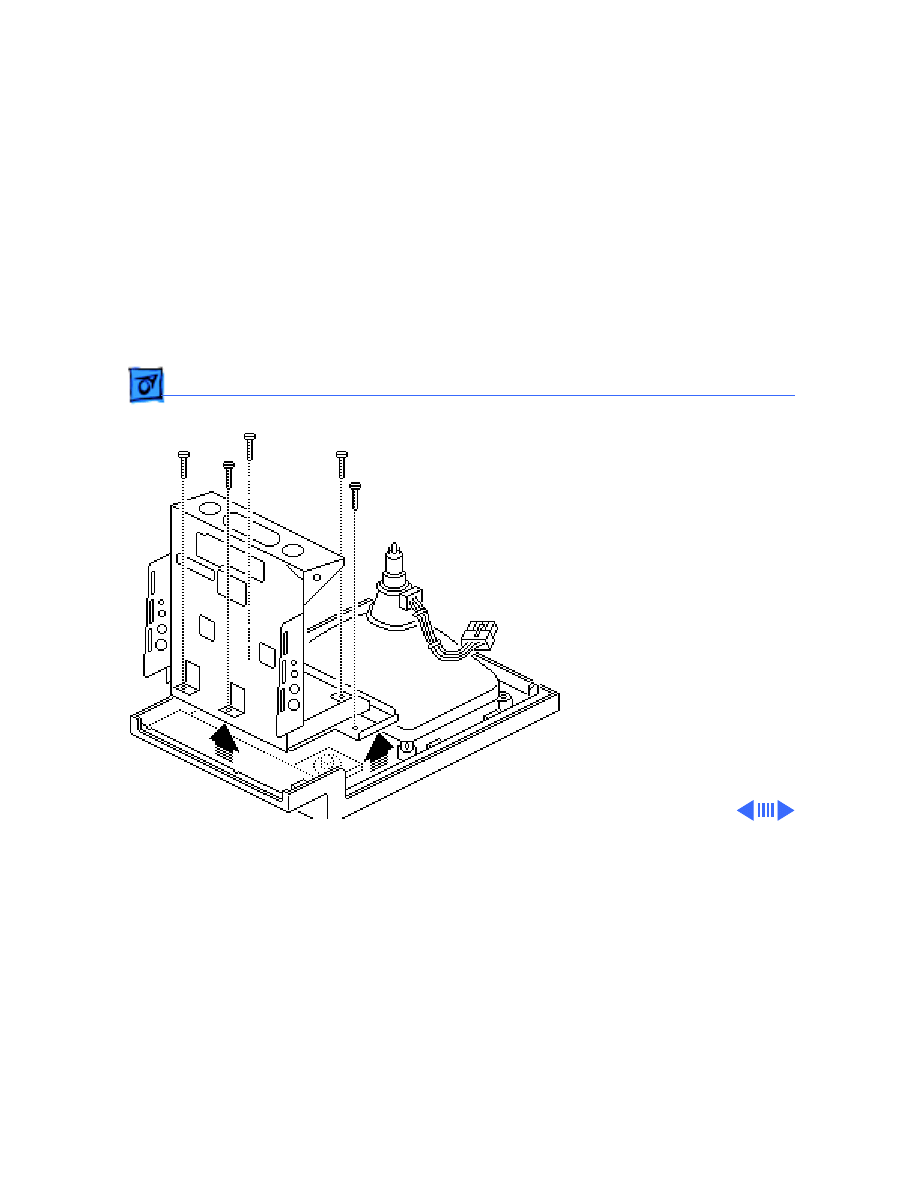
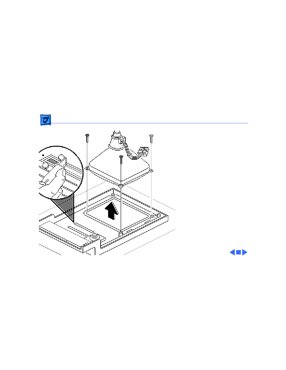
Hard Drive - 21
Hard Drive
Before you begin,
• Remove the cover
• Discharge the CRT
• Remove the video board
Hard Drive
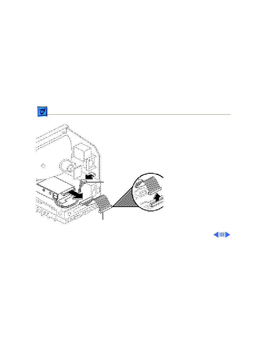
Take Apart
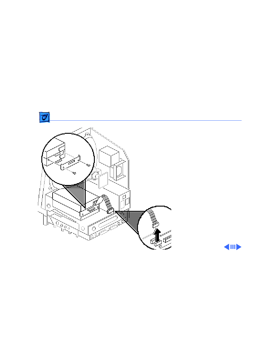
Hard Drive - 22
Warning:
Never use a
grounding wriststrap until
after discharging the CRT.
1 Disconnect the hard
drive data cable from the
hard drive and the logic
board. Keep the cable.
2 Disconnect the hard
drive power cable from
the analog board.
Hard Drive Data Cable
Hard Drive
Power Cable

Take Apart
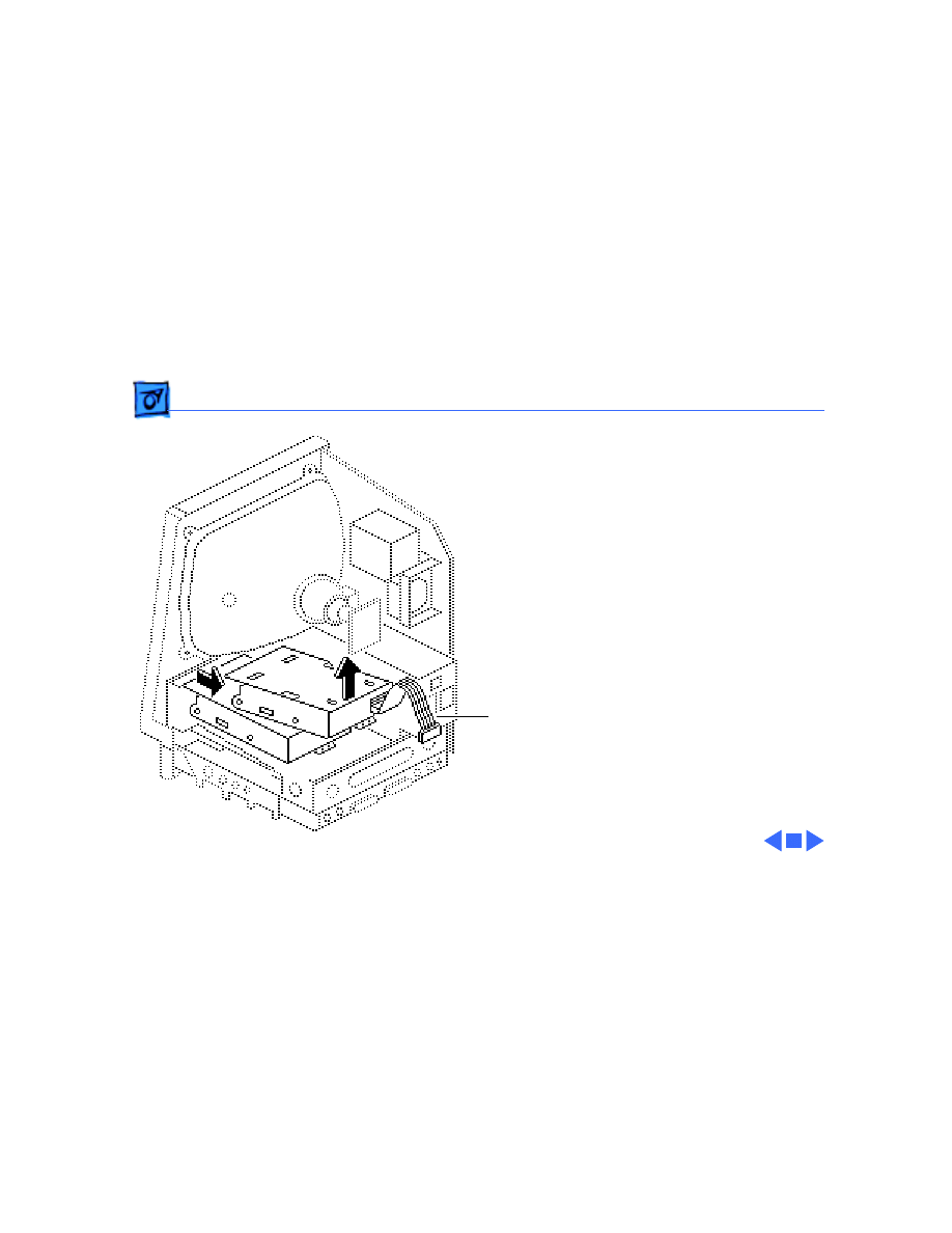
Hard Drive - 23
3 Remove the two
mounting screws and
lift out the hard drive
with carrier attached.
Replacement Note:
For
information on removing the
hard drive from the carrier
and returning drives,
cables, and carriers to
Apple, refer to “Additional
Procedures” in the Hard
Drives manual.
Take Apart
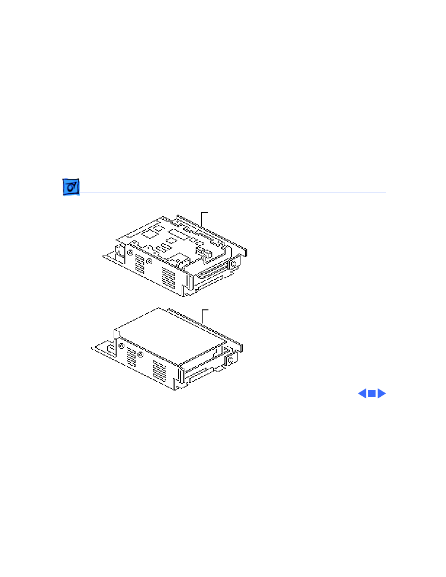
Hard Drive - 24
Replacement Note:
If you
are replacing a defective
Hard Disk 20SC, be aware
that Apple currently ships
Revision A and Revision B
versions of this hard drive
and each version must be
replaced like-for-like. To
differentiate between drive
versions, check their
circuit boards. For Revision
A drives, the component
side of the board is up; for
Revision B drives, the
solder side of the board is
up. For part numbers,
refer to the Service Source
parts database.
Revision B
Revision A
Take Apart
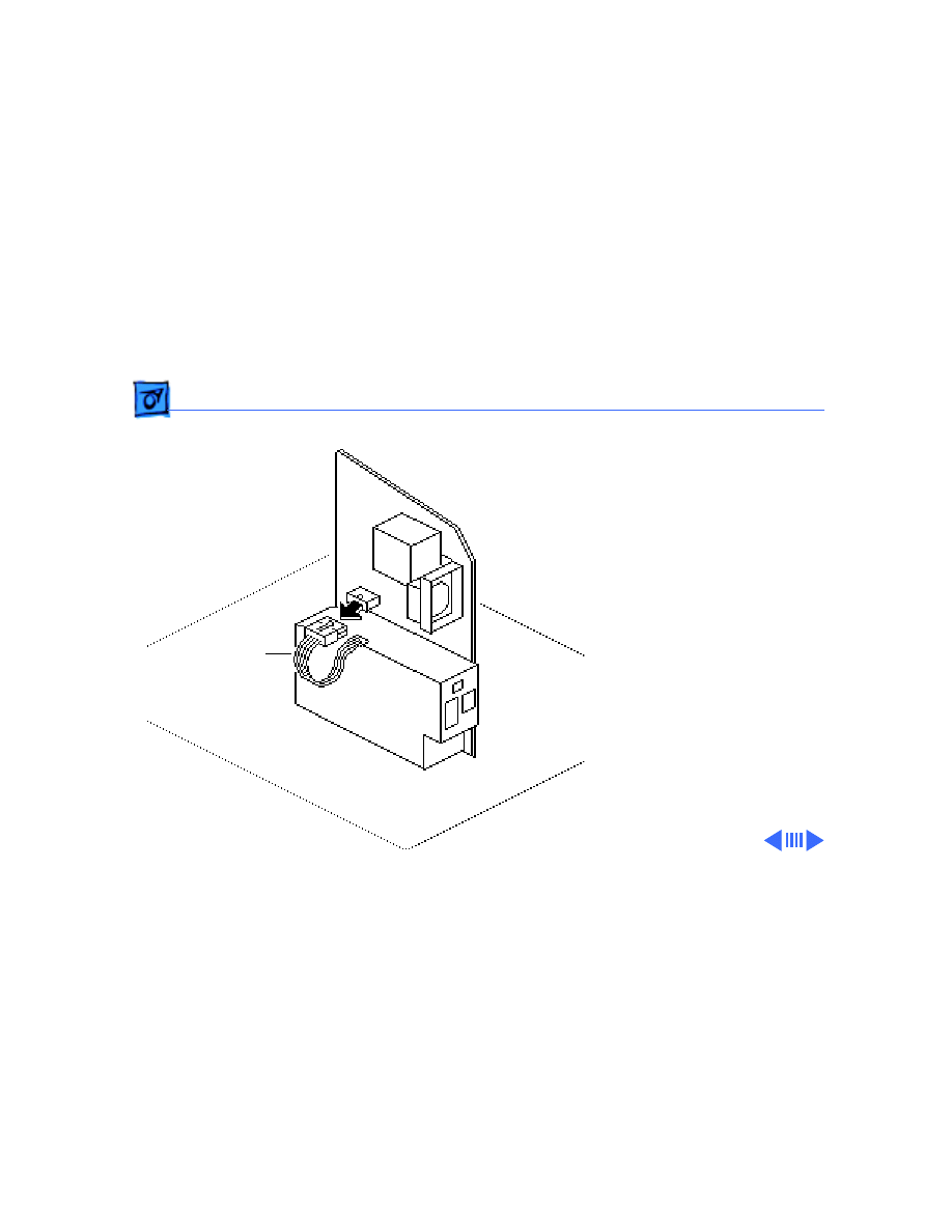
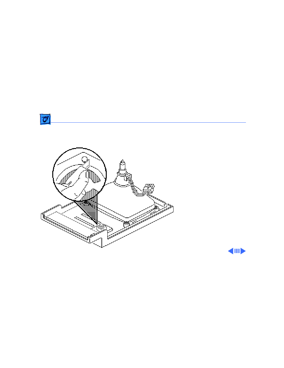
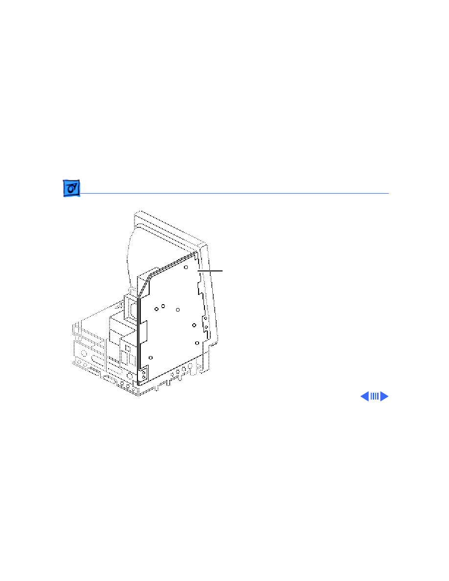
LED Cable Assembly - 25
LED Cable
Assembly
Before you begin,
• Remove the cover
• Discharge the CRT
• Remove the hard drive
LED Cable Assembly
Take Apart
LED Cable Assembly - 26
1 Disconnect the LED
connector from the hard
drive.
2 Pull open the release
tab at the back of the LED
and push the LED
through the carrier
bracket.
Take Apart
Upper Floppy Drive - 27
Upper Floppy
Drive
Before you begin,
• Remove the cover
• Discharge the CRT
• Remove the video board
Upper Floppy Drive
Take Apart
Upper Floppy Drive - 28
1 Disconnect the upper
floppy drive cable from
logic board connector J7.
2 Remove two mounting
screws and the metal
bracket that connects the
upper and lower floppy
drives.
Take Apart
Upper Floppy Drive - 29
3 Lift and slide out the
upper floppy drive.
Disconnect and keep the
floppy drive cable.
Replacement Note:
Apple
recommends using dust
shields on all 1.4 MB floppy
drives. All 1.4 MB
replacement drives ship
with the dust shield
installed. If you plan to
install a dust shield on an
existing 1.4 MB drive, you
must first clean the drive
(see the Hard Drives
manual).
Floppy Drive
Cable
Take Apart
Lower Floppy Drive - 30
Lower Floppy
Drive
Before you begin,
• Remove the cover
• Discharge the CRT
• Remove the video board
• Remove the upper drive
• Remove the logic board
Lower Floppy Drive
Take Apart
Lower Floppy Drive - 31
Remove the four mounting
screws and lift out the lower
floppy drive. Disconnect and
keep the floppy drive cable.
Replacement Note:
Apple
recommends using dust
shields on all 1.4 MB floppy
drives. All 1.4 MB
replacement drives ship
with the dust shield
installed. If you plan to
install a dust shield on an
existing 1.4 MB drive, you
must first clean the drive
(see the Hard Drives
manual).
Floppy Drive
Cable
Take Apart
Fan Assembly - 32
Fan Assembly
Before you begin,
• Remove the cover
• Discharge the CRT
• Remove the video board
• Remove the analog board
and power supply.
Fan Assembly
Take Apart
Fan Assembly - 33
1 Compress the arrow
clips and remove the
insulating paper from
the analog board.
Insulating Paper
Arrow Clips
Take Apart
Fan Assembly - 34
2 Check the front and back
of the analog board for
wires connecting the fan
to the board. Desolder
these wires at their
solder points at the back
of the analog board.
Using a matte knife, cut
away any excess solder.
(Solder Side)
Solder Point
(Component Side)
Fan Wires
Solder Point
Solder Point
Solder Point
Solder Point
Solder Point
Take Apart
Fan Assembly - 35
3 Remove the four
mounting screws and
lockwashers and remove
the fan assembly from
the analog board.
Note:
On earlier
versions of the analog
board you may have to
desolder the fan itself
from the analog board at
the solder points shown.
(Solder Side)
Fan Solder Points

Take Apart
Fan Assembly - 36
Replacement Caution:
If
you are replacing the fan
with the newer axial
(round) fan, make sure
your customer’s system has
the redesigned, vertically-
mounted video board
installed on the CRT. The
axial fan does not allow
adequate vibration
clearance with the old,
horizontally-mounted video
board.
Take Apart
Fan Assembly - 37
Replacement Note:
Some
replacement fans have a
black wire and a yellow wire
that must be soldered to the
back side of the analog board.
Insert these wires through
the arrow clip hole in the
board and solder them to the
points shown.
Black Wire
Yellow Wire
(Solder Side)
Take Apart
Speaker, Bezel, & Slot Cover - 38
Speaker, Bezel, &
Slot Cover
Before you begin,
• Remove the cover
• Discharge the CRT
• Remove the video board
• Remove the analog board
(only)
• Remove the logic board
Speaker,
Bezel, &
Slot Cover
Take Apart
Speaker, Bezel, & Slot Cover - 39
1 Remove the five Torx
screws and lift the
chassis (with attached
drives) off the front
bezel.
Take Apart
Speaker, Bezel, & Slot Cover - 40
2 To remove the speaker,
cut away (with a matte
knife) the melted
plastic that secures the
speaker to the inside of
the front bezel.
3 Lift out the speaker.
Take Apart
Speaker, Bezel, & Slot Cover - 41
4 To remove the slot
cover, cut away (with an
art knife) the melted
plastic that secures the
slot cover to the inside of
the front bezel.
5 To remove the front
bezel, remove the CRT.
(See “CRT” in Take
Apart).
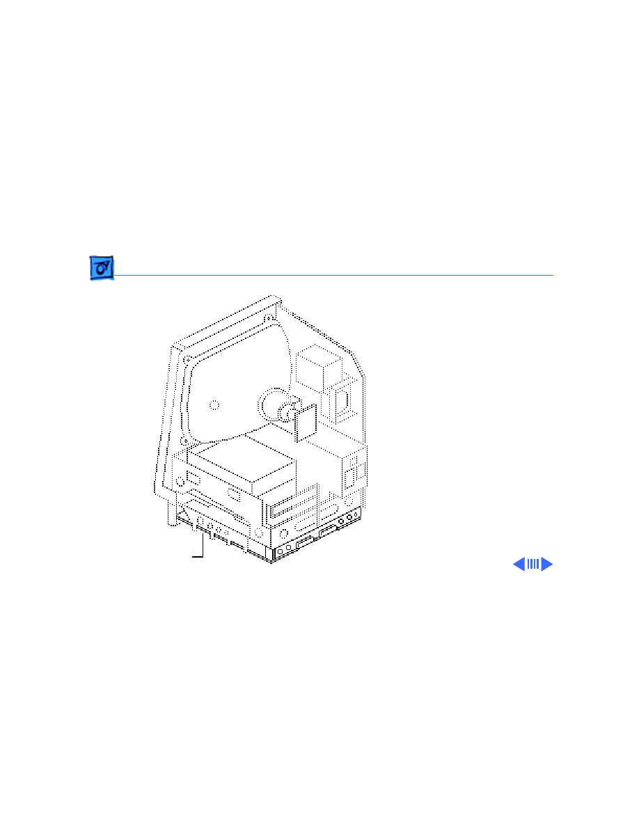
Service Source
K
Upgrades
Macintosh SE
Upgrades
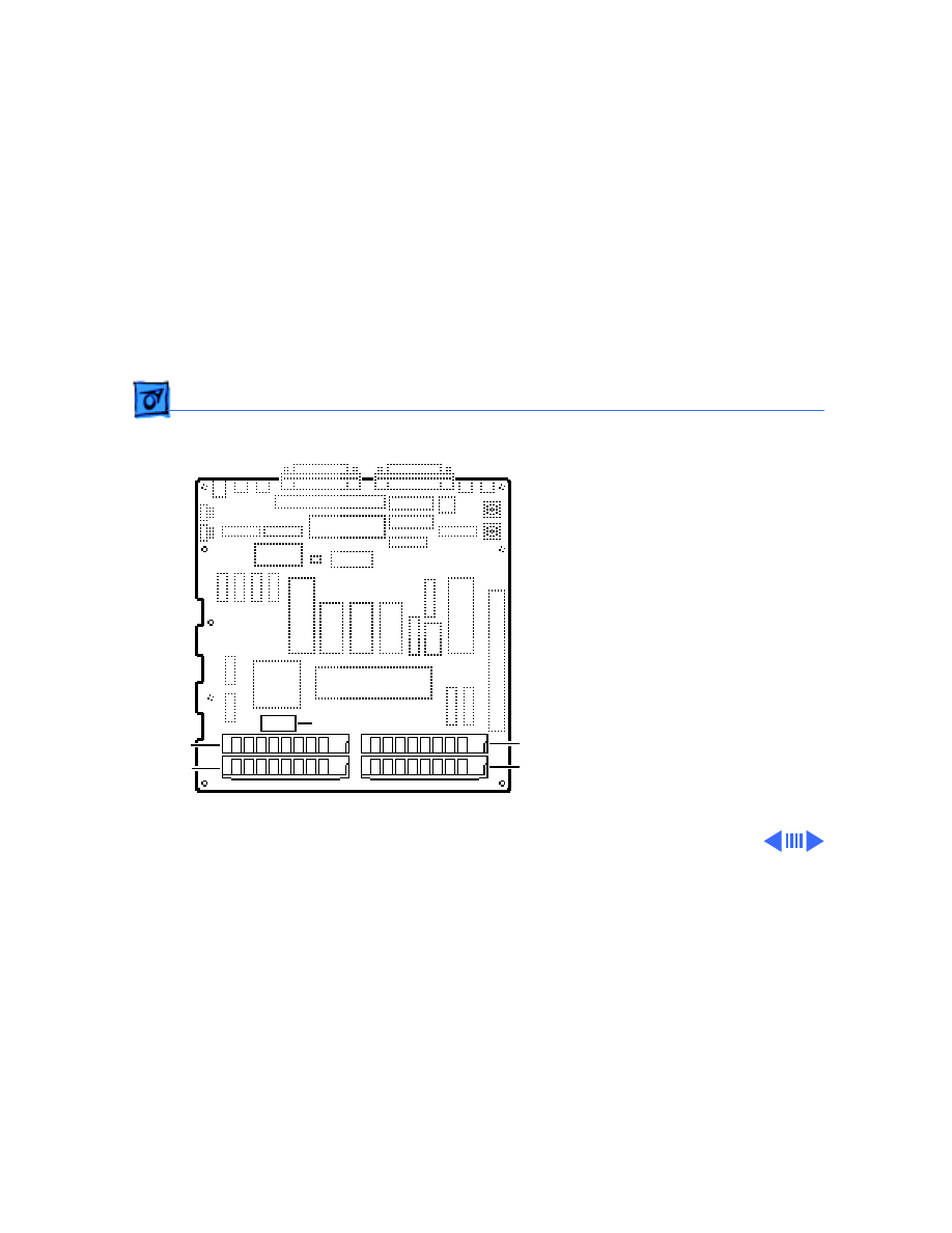
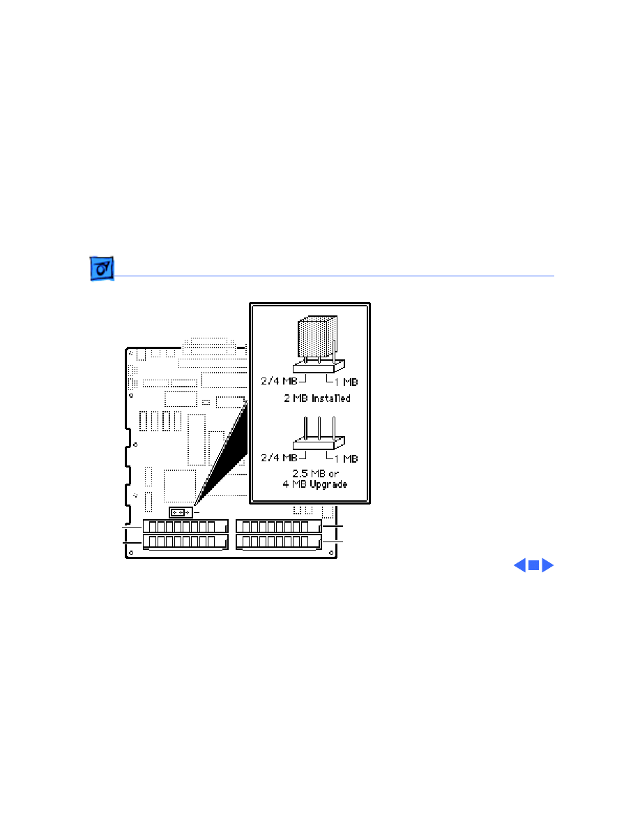
Memory Upgrade - 1
Memory Upgrade
Before you begin,
• Remove the cover
• Discharge the CRT
• Remove the logic board
±
Warning:
This product
contains high voltage and a
high-vacuum picture tube.
To prevent serious injury,
review CRT safety in
Bulletins/Safety.
±
Warning:
Never use a
grounding wriststrap until
after discharging the CRT.
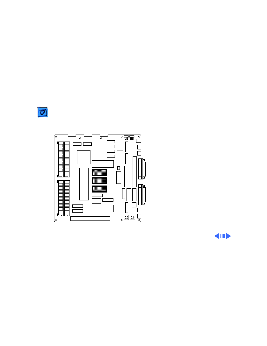
Logic Board
Upgrades
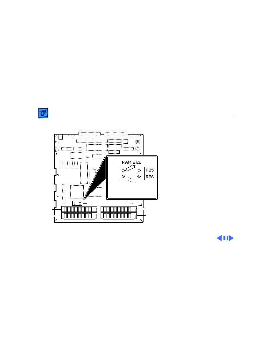
Memory Upgrade - 2
Note:
Two logic boards are
available for the Macintosh
SE. The original board uses a
solder-type resistor to
identify system memory
configurations; a resistor is
installed in R35 for 1 MB
and in R36 for 2 MB. The
revised logic board uses a
jumper to identify system
memory.
Resistor/Jumper
Slot 3
Slot 2
Slot 4
Slot 1

Upgrades
Memory Upgrade - 3
Note:
The Macintosh SE
requires 150-ns (or
faster) SIMMs. RAM speed is
indicated by the -xx number
after the manufacturer’s
part number (-15
indicates a 150-ns SIMM).
Upgrades
Memory Upgrade - 4
Logic Board with
Resistor
Clip one end of resistor R35
or R36 and move the
resistor away from the
clipped lead.
Replacement Note:
Clipping the resistor and
moving it away will allow
you to retack the resistor in
the future.
Slot 3
Slot 1
Slot 4
Slot 2
Resistor

Upgrades
Memory Upgrade - 5
2.5 MB Upgrade
Install two 1 MB SIMMs in
slots 1 and 2 and install two
256K SIMMs in slots 3 and
4.
4 MB Upgrade
Install four 1 MB SIMMs in
slots 1 through 4.
Upgrades
Memory Upgrade - 6
Logic Board with
Jumper
1 MB to 2.5 MB
Remove the two 256K
SIMMs from slots 3 and 4.
Install two 1 MB SIMMs in
slots 3 and 4. Remove the
jumper permanently.
1 MB to 4 MB
Remove all four 256K
SIMMs. Install four 1 MB
SIMMs. Remove the jumper
permanently.
Jumper
Slot 1
Slot 4
Slot 3
Slot 2

Upgrades
Memory Upgrade - 7
Note:
Disregard the jumper
label “2/4 M” on the logic
board. A 4 MB upgrade
requires the removal of the
jumper.Ê
Upgrades
Memory Upgrade - 8
2 MB to 2.5 MB
Install two 256K SIMMs in
slots 1 and 2. Remove the
jumper permanently.
2 MB to 4 MB
Install two 1 MB SIMMs in
slots 1 and 2. Remove the
jumper permanently.
Note:
Disregard the jumper
label “2/4 M” on the logic
board. A 4 MB upgrade
requires the removal of the
jumper.
Slot 1
Slot 4
Slot 3
Slot 2
Upgrades
Logic Board Upgrade - 9
Logic Board
Upgrade
Before you begin,
• Remove the cover
• Discharge the CRT
• Remove the video board
• Remove the logic board
• Remove the analog board
(only)
• Remove the upper drive
• Remove the CRT
• Remove the bezel
Logic Board

Upgrades
Logic Board Upgrade - 10
±
Warning:
This product
contains high voltage and a
high-vacuum picture tube.
To prevent serious injury,
review CRT safety in
Bulletins/Safety.
Caution:
After discharging
the CRT, wear a grounding
wriststrap to prevent ESD
damage to components.

Upgrades
Logic Board Upgrade - 11
Note:
The Logic Board
Upgrade Kit for the
Macintosh SE includes the
SE/30 logic board, a new
bezel, a ferrite bead and tie-
wrap for EMI protection, a
new chassis and bracket, a
new RFI shroud, two labels,
and a return sheet that you
must fill out and return to
Apple with the SE logic
board.
Upgrades
Logic Board Upgrade - 12
Note:
The SE/30 logic
board requires a minimum
of four identical RAM
SIMMs. Customers whose
Macintosh SE systems have
2.5 MB or less of RAM must
purchase additional RAM
SIMMs.
Note:
The new chassis
comes in two pieces (a
chassis and a bracket) that
you must assemble before
installation.
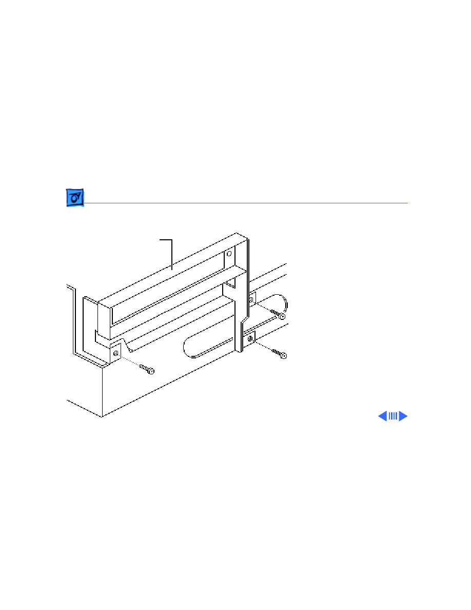
1 Install the bracket on the
chassis with three
mounting screws.Ê
Chassis Bracket
Upgrades
Logic Board Upgrade - 13
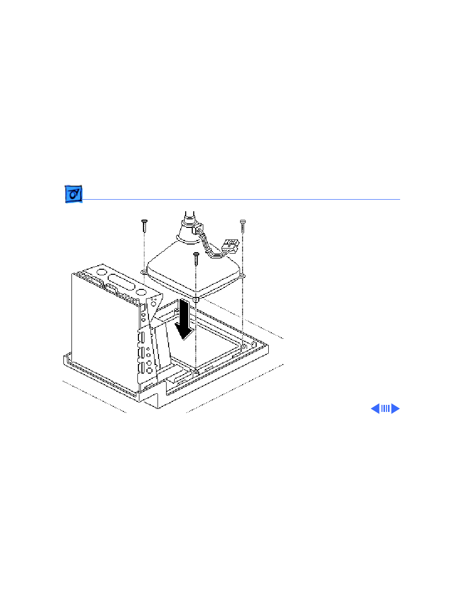
2 Install the CRT on the
new bezel with three
Torx screws.
3 Remove the lower
floppy drive from the old
chassis and install it on
the new chassis. Refer
to “Lower Floppy
Drive” in Take Apart.
Upgrades
Logic Board Upgrade - 14
4 Install the new chassis
on the new bezel with
five Torx screws.
5 Install the hard drive or
upper floppy drive on
the new chassis. Refer
to “Hard Drive” or
“Upper Floppy Drive”
in Take Apart.
6 Replace the analog board.
Refer to “Analog Board”
in Take Apart.
7 Install the new SE/30
logic board. Refer to
“Logic Board” in Take
Apart.
Upgrades
Logic Board Upgrade - 15
8 Clasp the clip-on ferrite
bead around the video
board cable as near the
video board connector as
possible. Secure the
ferrite bead near the
connector with tie-
wraps.
9 Replace the video board.
Refer to “Video Board”
in Take Apart.
10 Install the new
insulating shroud over
the bottom of the SE and
replace the cover. Refer
to “Cover” in Take
Apart.
Tie-Wrap
Ferrite Bead
Upgrades
Logic Board Upgrade - 16
11 Attach the agency
approval label over the
previous agency label on
the back of the cover.
12 Attach the appropriate
drive label in the groove
to the left of the disk
drive slot on the new
bezel.
13 Install system software
(6.03 or later) and run
diagnostics on the
upgraded unit.
Agency Approval Label
Drive Labels
Upgrades
1.4 MB Drive Upgrade - 17
1.4 MB Drive
Upgrade
Before you begin,
• Remove the cover
• Discharge the CRT
• Remove the video board
• Remove the hard drive or
upper floppy drive
• Remove the logic board
• Remove the lower floppy
drive

Upgrades
1.4 MB Drive Upgrade - 18
±
Warning:
This product
contains high voltage and a
high-vacuum picture tube.
To prevent serious injury,
review CRT safety in
Bulletins/Safety.
±
Warning:
Never use a
grounding wriststrap until
after discharging the CRT.

Upgrades
1.4 MB Drive Upgrade - 19
Note:
The 1.4 MB
SuperDrive Upgrade Kit
available for the Macintosh
SE includes two new ROMs, a
SWIM disk controller chip,
an audio extension cable for
reducing EMI interference,
the new 1.4 MB SuperDrive,
system software, two labels,
and an Apple product return
form.
Upgrades
1.4 MB Drive Upgrade - 20
Note:
The 1.4 MB
SuperDrive must be used
with system software
version 6.0.3 or higher or
the Macintosh SE mistakes
the high-density drive for
an 800K mechanism.
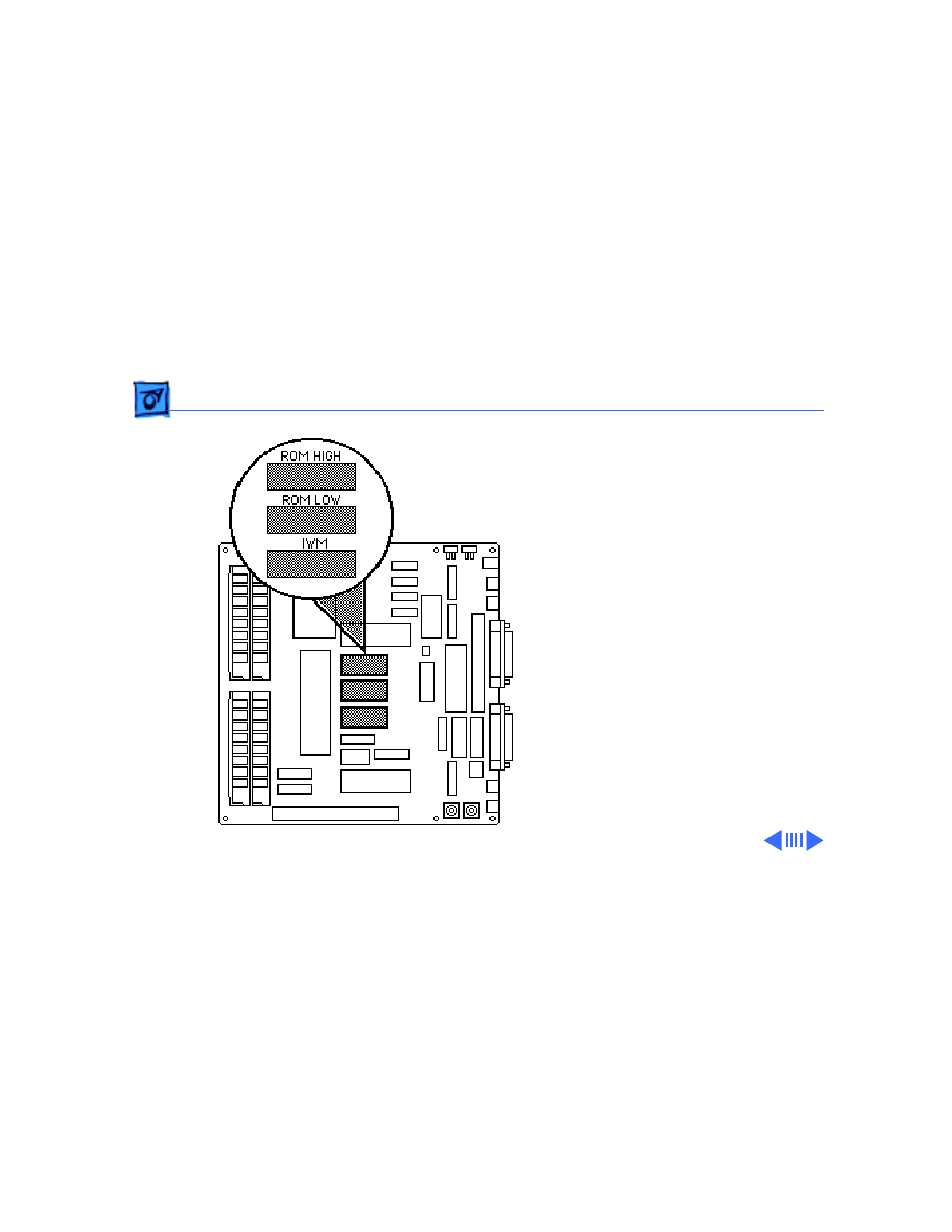
1 Using an IC extractor,
remove the IWM chip
and two ROM chips from
the logic board.
Upgrades
1.4 MB Drive Upgrade - 21
2 Install the SWIM chip
and two new ROM chips
on the logic board as
follows:
• SWIM (344–0062)
at D8
• High ROM (342–
0701) at D6
• Low ROM (342–
0702) at D7
Note:
The notch at one
end of the SWIM chip and
each ROM chip must face
toward the RAM SIMMs.
RAM SIMMs
RAM SIMMs
Upgrades
1.4 MB Drive Upgrade - 22
3 Install the lower floppy
drive (the new 1.4 MB
drive). Refer to “Lower
Floppy Drive” in Take
Apart.
4 Replace the logic board.
Refer to “Logic Board”
in Take Apart.
Upgrades
1.4 MB Drive Upgrade - 23
5 Replace the hard drive
or upper floppy drive.
Refer to “Hard Drive”
or “Upper Floppy
Drive” in Take Apart.
6 Replace the video board
and the cover. Refer to
“Video Board” and
“Cover” in Take Apart.
7 Place the high density
drive label in the groove
next to the lower drive
slot. If appropriate,
place a second floppy
drive label next to the
upper drive slot.
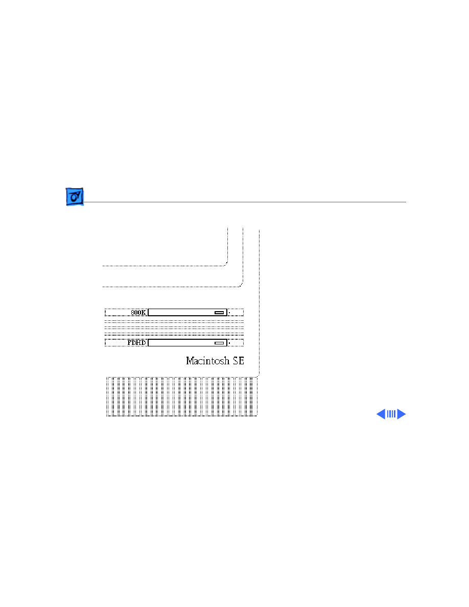
Upgrades
1.4 MB Drive Upgrade - 24
Note:
The high density
drive label may read
“FDHD,” “1.4 MB,” or
“SuperDrive.”
8 If necessary, install
system software (6.03
or higher) and run
diagnostics.
9 Fill out the Apple
product return form and
return it to Apple with
the two ROM chips and
the IWM chip.

Upgrades
1.4 MB Drive Upgrade - 25
Note:
Give the customer the
audio extension cable and
explain its use. To reduce
EMI interference, the
customer must install the
audio extension cable with
the ferrite bead between the
audio cable and the audio
jack at the rear of the
computer.
Service Source
K
Additional Procedures
Macintosh SE
Additional Procedures
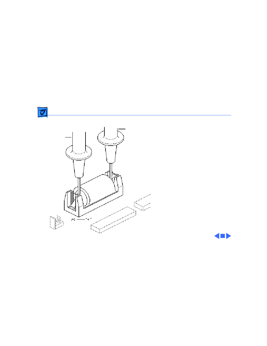
Battery Verification - 1
Battery
Verification
Before you begin,
• Remove the cover
• Discharge the CRT
• Remove the logic board
±
Warning:
If handled or
discarded improperly, the
lithium battery in the
Macintosh SE/30 could
explode. Review battery
handling and disposal
instructions in Bulletins/
Safety.
Battery
Additional Procedures
Battery Verification - 2
±
Warning:
Never use a
grounding wriststrap until
after discharging the CRT.
1 Set the voltmeter to the
10 volts DC scale.
2 Hold the positive probe
of the voltmeter to the
positive end of the
battery and the negative
probe to the negative
end of the battery.
3 If the battery voltage is
below 2.8 volts, replace
the battery. Refer to
“Battery Replacement”
in this chapter.
Negativ
e
Positive
Probe
Probe
Additional Procedures
Battery Replacement - 3
Battery
Replacement
Before you begin,
• Remove the cover
• Discharge the CRT
• Remove the logic board
±
Warning:
If handled or
discarded improperly, the
lithium battery in the
Macintosh SE/30 could
explode. Review battery
handling and disposal
instructions in Bulletins/
Safety.
Battery

Additional Procedures
Battery Replacement - 4
Caution:
Never use a
grounding wriststrap until
after discharging the CRT.
Additional Procedures
Battery Replacement - 5
Soldered Battery
1 Using wire clippers, cut
the battery leads at both
ends of the battery. Cut
the leads as close to the
logic board as you can
without touching the
board.
2 Return the battery to
Apple for proper
disposal. For battery
packaging and labeling
information, refer to the
instructions in
Bulletins/Safety.
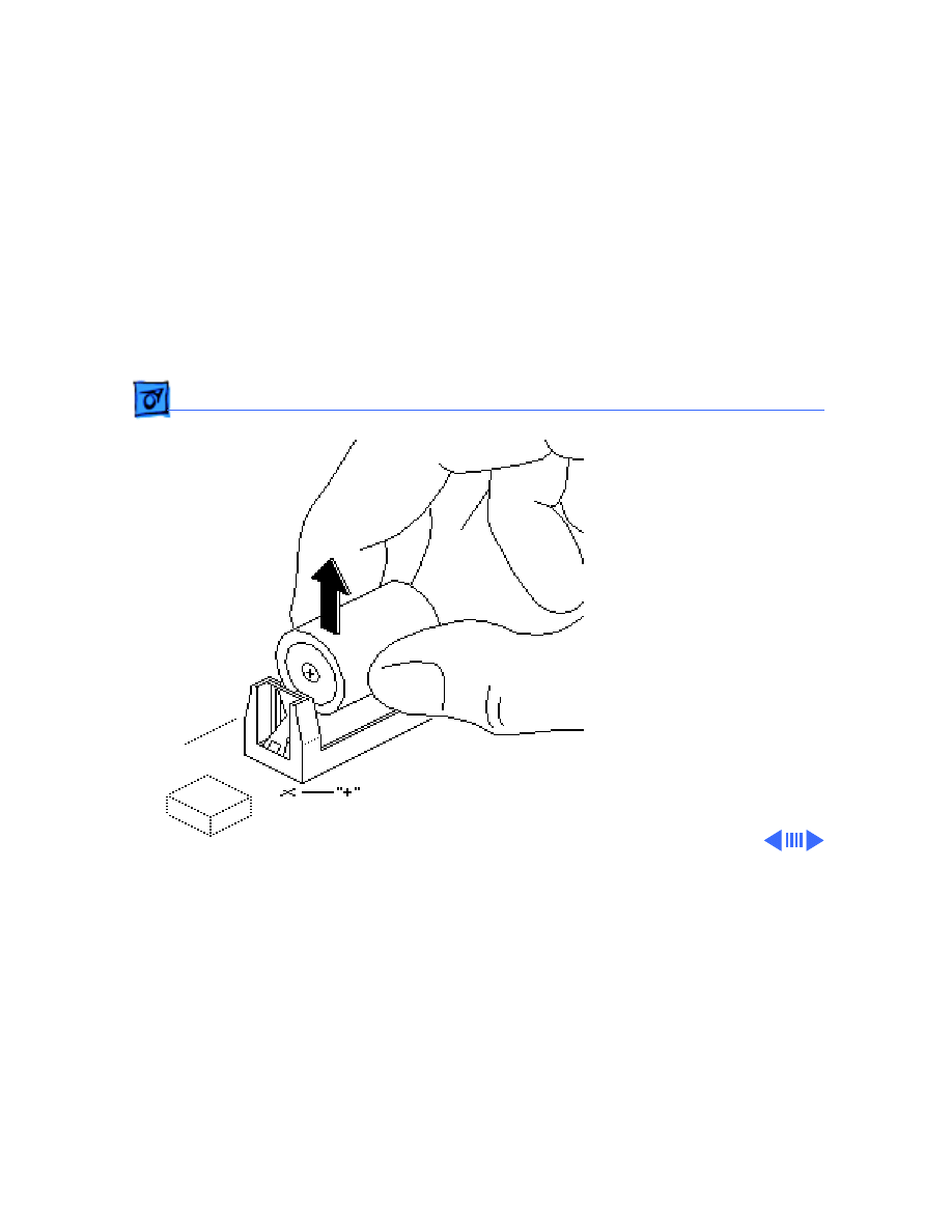
Additional Procedures
Battery Replacement - 6
Battery in a Battery
Holder
1 Pull the battery out of
the battery holder.
2 Return the battery to
Apple for proper
disposal. For battery
packaging and labeling
information, refer to the
instructions in
Bulletins/Safety.
Additional Procedures
Battery Replacement - 7
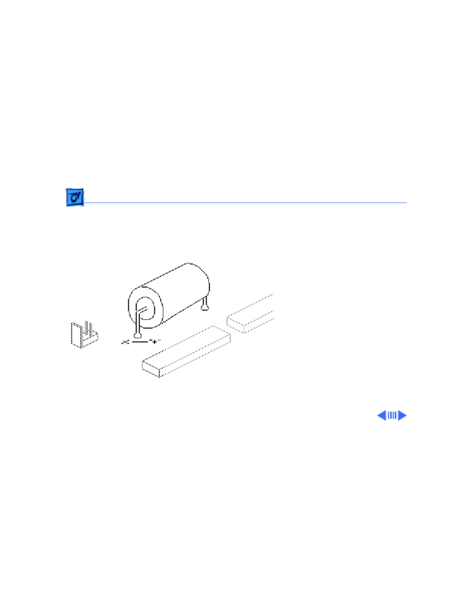
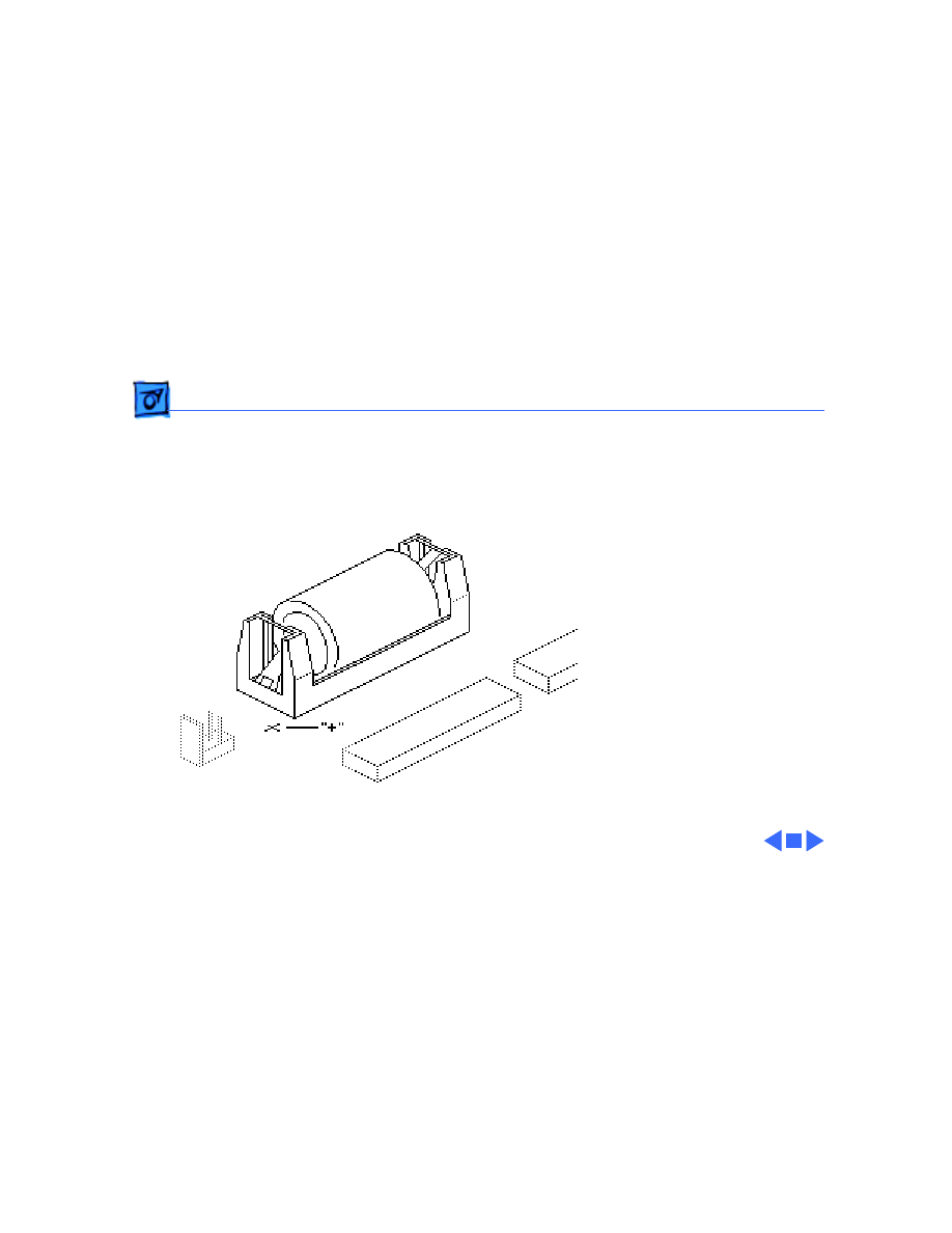
Replacement Note:
When
replacing the new battery,
orient it so that the end
marked “+” matches the
“+” on the logic board.
Replacement Note:
On
solder-type logic boards,
insert the leads of the new
battery into the extra set of
mounting holes just inside
the original mounting holes.
Additional Procedures
Chassis Tab Modification - 8
Chassis Tab
Modification
Before you begin, remove
the cover.
Note:
The chassis on some
Macintosh SE computers has
protruding tabs that may
interfere with the
installation of some third-
party cards. If you
encounter this problem,
perform the chassis tab
modification procedure.
Chassis
Chassis Tab
Additional Procedures
Chassis Tab Modification - 9
Using pliers, bend the tab
nearest the rear of the
chassis until the tab is flush
with the side panel.
Additional Procedures
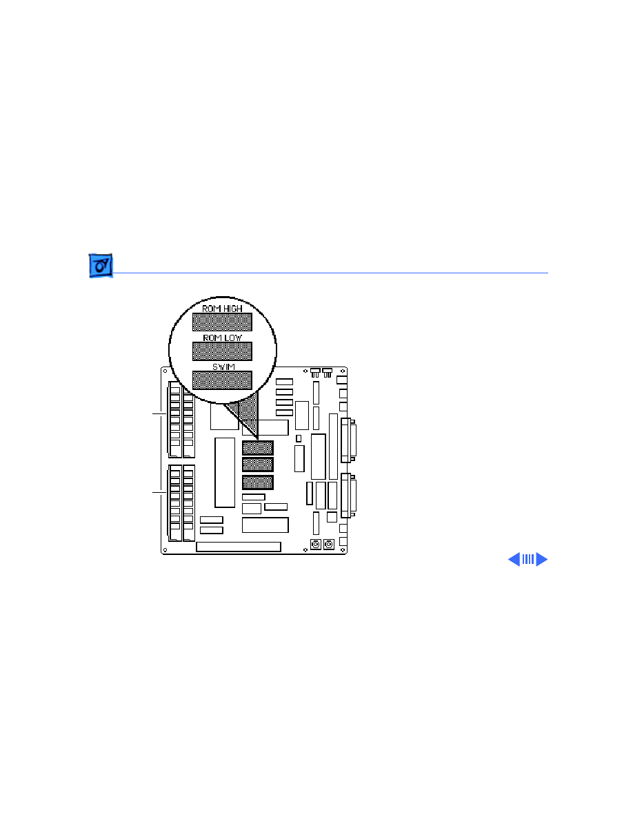
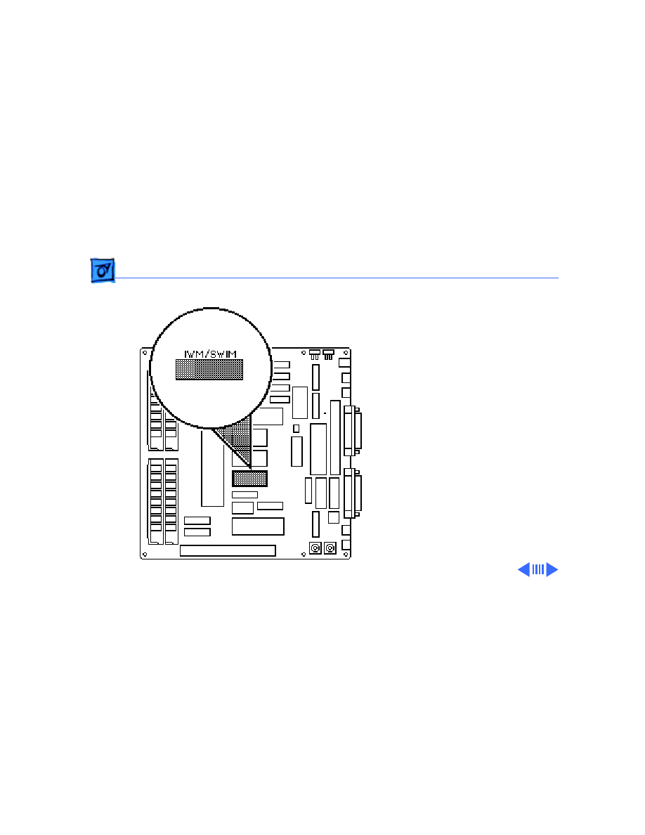
Identifying SE Logic Boards - 10
Identifying SE
Logic Boards
Before you begin,
• Remove the cover
• Discharge the CRT
• Remove the logic board
IWM/SWIM Chip
Battery

Additional Procedures
Identifying SE Logic Boards - 11
Two logic boards are
available as exchange
modules for the Macintosh
SE. If you are replacing the
logic board of an SE that was
originally shipped with a
1.4 MB SuperDrive, use
logic board 661-0536. If
you are replacing the logic
board of an SE that was
originally shipped with an
800K floppy drive, or an SE
that has been upgraded to use
a 1.4 MB SuperDrive, use
replacement logic board
661-0526.
Additional Procedures
Identifying SE Logic Boards - 12
Follow these guidelines to
help identify the correct
exchange module:
• If the customer’s
battery is installed in
a battery holder, use
replacement logic
board 661-0536.
• If the customer’s
battery is soldered to
the logic board, check
the part number on
the customer’s disk
controller chip. (See
the following
procedure.)
Additional Procedures
Identifying SE Logic Boards - 13
• If the disk controller is
an IWM chip (the part
number is not 344-
0062), use replacement
logic board 661-0526.
• If the disk controller is a
SWIM chip (part number
344-0062), use
replacement logic board
661-0526 and swap the
customer’s SWIM chip
and ROM chips for the
IWM chip and ROM chips
on the replacement
board. (See the following
procedure.)
Additional Procedures
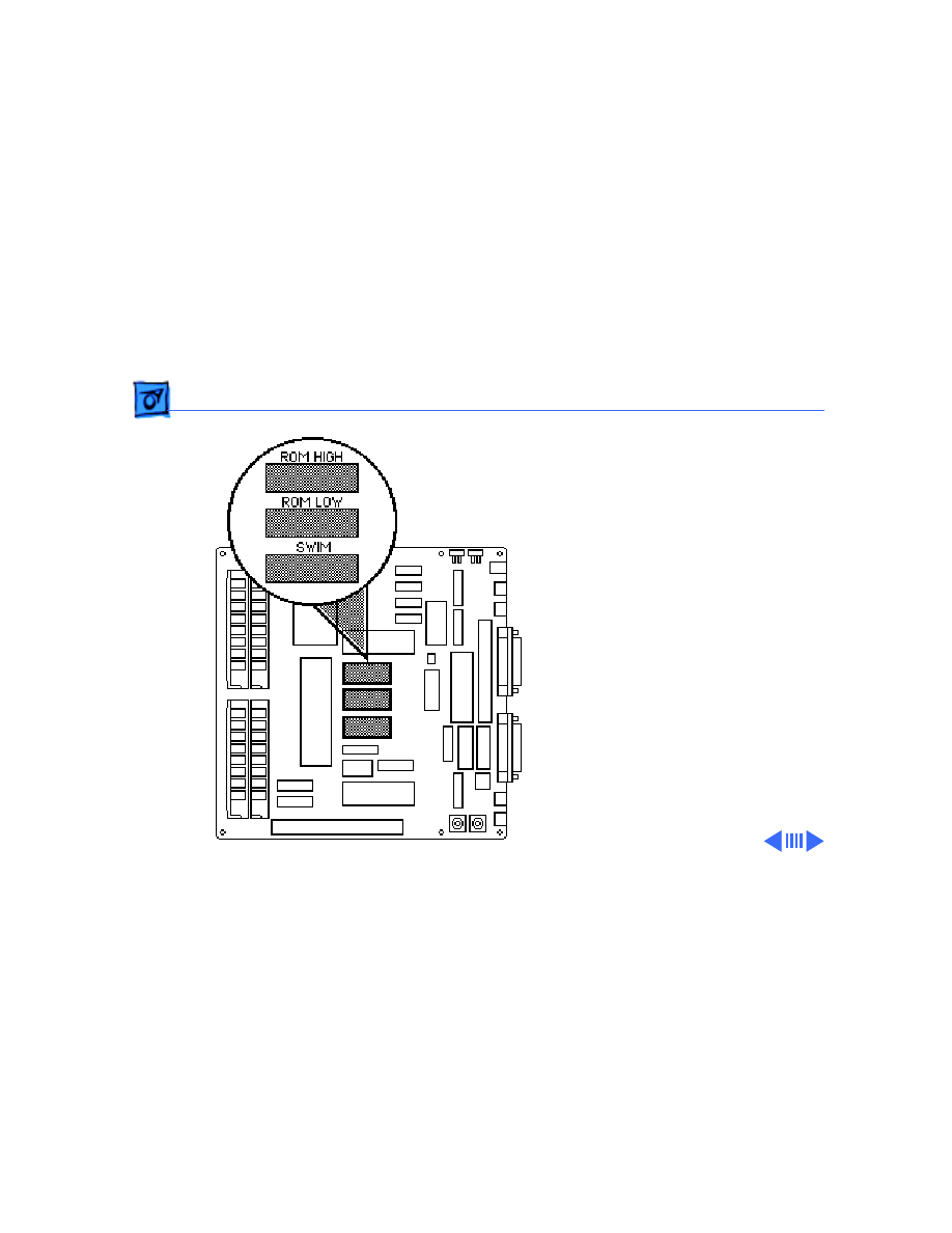
Identifying SE Logic Boards - 14
Note:
Failure to transfer
the customer’s SWIM chip
and upgraded ROM chips to
the replacement logic board
will prevent a 1.4 MB
SuperDrive from using
high-density media.
1 Using an IC extractor,
remove these chips
from the customer’s
logic board and install
them on the replacement
logic board:
• SWIM (344-0062)
at D8
• High ROM (342-
0701) at D6

Additional Procedures
Identifying SE Logic Boards - 15
• Low ROM (342-
0702) at D7
Note:
The notch at one
end of the SWIM chip and
each ROM chip must face
toward the RAM SIMMs.
2 Return the ROMs and
IWM chip to Apple on the
faulty logic board.
Service Source
K
Adjustments
Macintosh SE
Adjustments
Yoke - 1
Yoke
Before you begin,
• Remove the cover
• Discharge the CRT
±
Warning:
This product
contains high voltage and a
high-vacuum picture tube.
To prevent serious injury,
review CRT safety in
Bulletins/Safety.
Yoke

Adjustments
Yoke - 2
Warning:
Because you must
make yoke adjustments from
the rear of the computer,
use a mirror to view the
computer screen. Do not
reach around the computer
to adjust collars and rings.
Note:
If you replace the
CRT, you will probably need
to adjust the yoke.
Adjustments
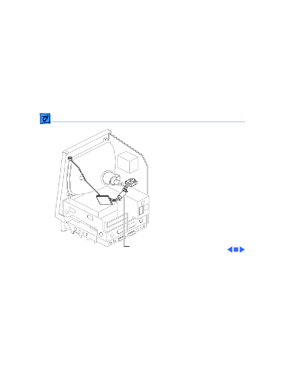
Yoke - 3
Tilt Adjustment
Note:
If glue is holding the
yoke collar in place, cut
through the glue using an art
knife.
1 Loosen the yoke clamp
screw two or three
turns.
2 Switch on the computer.
Yoke Collar
Yoke Clamp
Screw
Adjustments
Yoke - 4
3 With one hand, grasp
the plastic spokes of the
yoke collar, and rotate
the yoke collar until the
top and bottom edges of
the picture are parallel
with the top and bottom
of the bezel.
Ê
Plastic Spokes
Yoke Collar
Adjustments
Yoke - 5
4 Switch off and unplug the
computer.
5 Discharge the CRT.
6 Hold the plastic collar
in position and carefully
tighten the yoke clamp
screw so that the collar
cannot slip. Do not
overtighten the screw.
7 Replace the cover and
switch on the computer.
Make sure the top and
bottom edges of the
picture are parallel with
the top and bottom of the
bezel.
Yoke Collar
Yoke Clamp
Screw

Adjustments
Yoke - 6
Centering Ring
Adjustment
Note:
If glue holds the yoke
collar in place, use an art
knife to cut through the glue.
1 Switch on the computer.
2 To center the picture
within the bezel: Hold
the front centering ring
steady and move the
rear ring; then hold the
rear centering ring
steady and move the
front ring.
Centering Rings
Adjustments
Video - 7
Video
Before you begin, remove
the cover.
±
Warning:
This product
contains high voltage and a
high-vacuum picture tube.
To prevent serious personal
injury or equipment
damage, review the CRT
safety instructions in
Bulletins/Safety.
Analog Board

Adjustments
Video - 8
Warning:
Because you must
make video adjustments
from the rear of the
computer, use a mirror to
view the computer screen.
Do not reach around the
computer to adjust the
controls.
Note:
You may need to
perform video adjustments
after you replace the CRT,
analog board, video board, or
power supply. The video
adjustment controls are
located on the analog board.
Adjustments
Video - 9
Brightness and
Contrast
1 Turn the external
contrast control fully
clockwise.
2 Using the plastic
alignment tool, adjust
the brightness control
counterclockwise so that
white lines are visible
on the screen. Turn the
brightness control
clockwise until the white
lines just disappear.
Brightness
Control
External
Contrast
Control

Adjustments
Video - 10
3 Turn the brightness
control
counterclockwise
slightly.
Adjustments
Video - 11
Size Adjustments
1 Using the plastic hex
alignment tool, adjust
width until the raster is
7 inches wide.
2 Using the plastic hex
alignment tool, adjust
the height until the
raster is 4.7 inches
high.
Ê
Width
Control
Height
Control
Adjustments
Video - 12
Focus
Turn the focus control fully
clockwise, then turn the
focus control counter-
clockwise one-eighth of a
turn.
Focus
Control
Service Source
K
Exploded View
Macintosh SE
Exploded View
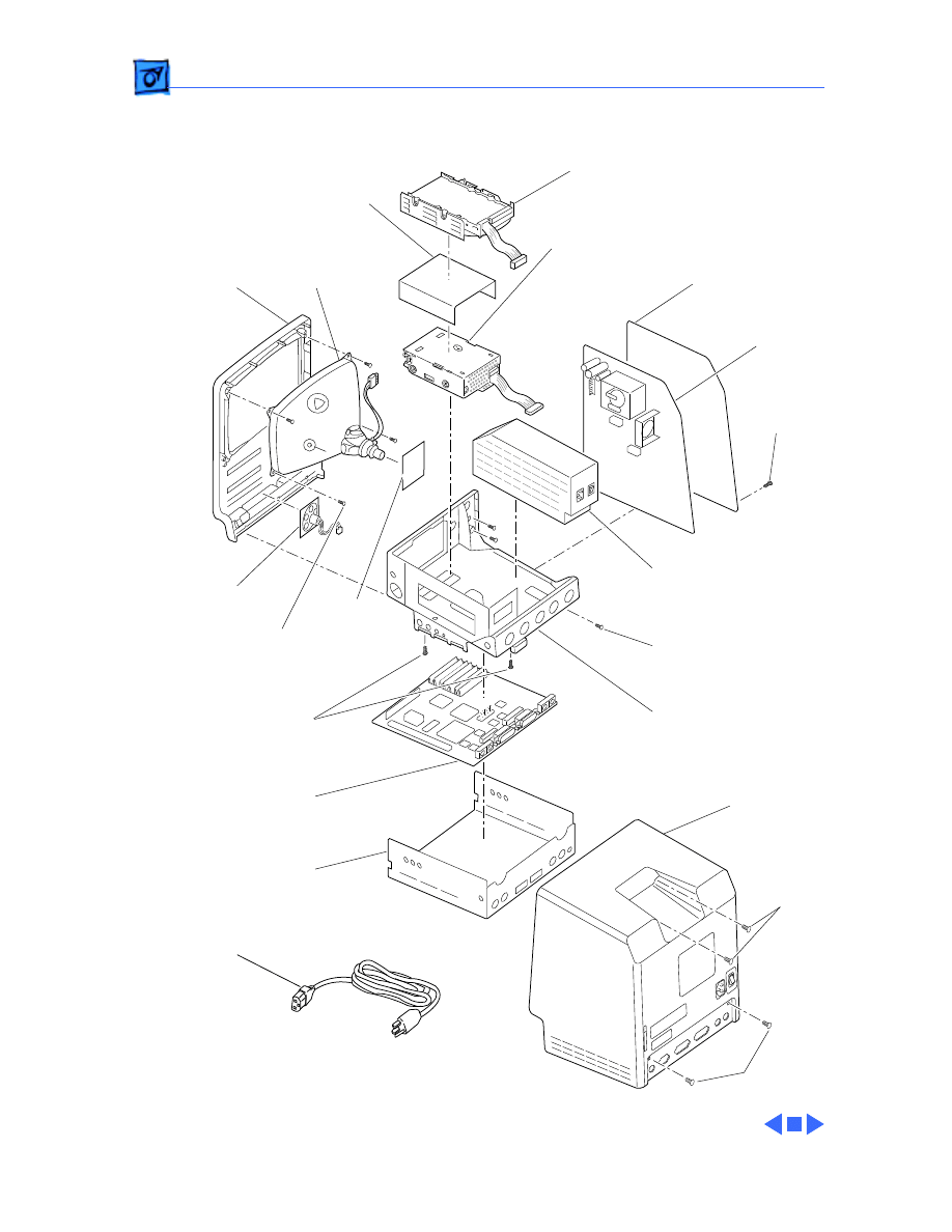
1
Exploded View
435-5002
RFI
Shroud
805-5060
Logic
Board
6i61-0530
Chassis
805-0938
426-1007
Rear
Housing
630-5271
Insulator
Shield
725-0020
470-2101
Power
Supply
661-0370
Analog
Board
661-0371
Floppy Drive
661-0345 (800K)
661-0474 (1.4 MB)
Hard Drive
661-0216 (40 MB)
Video
Board
982-0024
Front
Bezel
810-0399
810-0422
(for SuperDrive)
CRT and Yoke
Assembly
076-0103
Dust Shield
076-0439
Speaker
600-0393
426-1001
Power
Cable
590-0380
462-4100
470-2101
Document Outline
- Macintosh SE
- Basics
- Specifications
- Troubleshooting
- Take Apart
- Upgrades
- Additional Procedures
- Adjustments
- Exploded View
Wyszukiwarka
Podobne podstrony:
Macintosh SE, ● Mója Kolekcja Zbiorów komputerów Zabytkowe
macintosh se 30
Dzieci ofiary przestępstw se
Cómo se dice Sugerencias y soluciones a las actividades del manual de A2
Apple Macintosh(1), Studia, Informatyka, Informatyka, Informatyka
wniosek racjonalizatorski icp koliberII(1), ( ͡~ ͜ʖ ͡°) rozwiń horyzonty
rok IV se zimowa t?
Se laver
ms+excel+a+prace+se+vzorci+cz N3VZFNCF44ZMVBX7PGJOYQMEBIWIY54GYV6NZYA
SE, pedagogika
20'', Politechnika Lubelska, Studia, semestr 5, Sem V, Sprawozdania, sprawozdania, Sprawozdania, Lab
Protel 99 SE projektowanie Obwodow Drukowanych
Mercedes Lackey SE 6 Spiritride
hleda se zdravy clovek
14'''''''''', Politechnika Lubelska, Studia, semestr 5, Sem V, Sprawozdania, sprawozdania, Sprawozda
Sześć najlepszych akcji sezonu 11 w SE
Se
GPC SE~1 id 193962 Nieznany
więcej podobnych podstron