
C O O L I N G
S Y S T E M
Return To Main Table of Contents
GENERAL . . . . . . . . . . . . . . . . . . . . . . . . . . . . . . . . . . . . . . . . . . . . . .
COOLING SYSTEM . . . . . . . . . . . . . . . . . . . . . . . . . . . . . . . . . . . . .
RADIATOR . . . . . . . . . . . . . . . . . . . . . . . . . . . . . . . . . . . . . . . . . . . .
WATER PUMP . . . . . . . . . . . . . . . . . . . . . . . . . . . . . . . . . . . . . . . . 1 3
THERMOSTAT . . . . . . . . . . . . . . . . . . . . . . . . . . . . . . . . . . . . . . . . .
WATER TEMPERATURE GAUGE UNIT, SENSOR . . . . . 16
WATER HOSE AND PIPE . . . . . . . . . . . . . . . . . . . . . . . . . . . . .
GENERAL
GENERAL
SPECIFICATIONS
Cooling method
Cooling system
Quantity
Radiator cap
Main valve opening pressure
Vacuum valve opening pressure
Water pump
Thermostat
Valve opening temperature
Full-opening temperature
Valve lift, fully open
Identification mark
Water temperature gauge unit
Resistance
Thermo switch (On radiator)
Operating temperature
Water temperature sensor
Resistance
Water-cooled, pressurized,
Forced circulation with electrical fan
5.3 lit (5.6 U.S.qts., 5.0 Imp.qts.)
81.4-108 kPa (11.8-15.6 psi, 0.83-1.1 kg/cm*)
-6.86 kPa (-1.00 psi, -0.07 kg/cm*) or less
Impeller of centrifugal type
88 ± 1.5°C (190.4 ± 2.7°F)
100°C (212°F)
8 mm (0.31 in) or more
88 (Stamped on flange)
90.5-117.5 at 70°C (158°F)
21.3-26.3 at 115°C (239°F)
85 ± 3°C (185 ± 5.4°F)
78°C (172°F) or more
2.21-2.69
at 20°C (68°F)
264-328 at 80°C (176°F)
SERVICE STANDARD
Standard value
Coolant concentration
50%
2 5 - 2
TIGHTENING TORQUE
Nm
kg.cm
lb.ft
Alternator support nut
Alternator adjuster lock bolt
Water pump to cylinder block
Water pump to cylinder block (alternator brace mounting)
Water pump pulley
Water temperature gauge unit
Water temperature sensor
Water outlet fitting bolt
2 0 - 2 5
2 0 0 - 2 5 0
1 4 - 1 8
1 2 - 1 5
1 2 0 - 1 5 0
9 - 1 1
1 2 - 1 5
1 2 0 - 1 5 0
9 - 1 1
2 0 - 2 6
2 0 0 - 2 7 0
1 4 - 2 0
8 - 1 0
8 0 - 1 0 0
6 - 7
1 0 - 1 2
1 0 0 - 1 2 0
7 - 9
2 0 - 3 9
2 0 0 - 4 0 0
1 5 - 2 8
1 7 - 2 0
1 7 0 - 2 0 0
1 2 - 1 4
2 5 - 3

GENERAL
TROUBLESHOOTING
Symptom
Low coolant level
Clogged radiator
Abnormally high coolant
temperature
Abnormally low coolant
temperature
Leakage from oil cooling
system
Inoperative electrical
cooling fan
Probable cause
Leakage of coolant
Heater or radiator hose
Faulty radiator cap
Thermostat housing
Radiator
Water pump
Foreign material in coolant
Faulty thermostat
Faulty radiator cap
Restricted to flow in cooling system
Loosen or missing drive belt
Faulty water pump
Faulty temperature gauge or wiring
Faulty electric fan
Faulty thermo-switch in radiator
Insufficient coolant
F a u l t y t h e r m o s t a t
Faulty temperature gauge or wiring
Loose connections
Cracked or damaged
Hoses
Pipes
Oil cooler
Damaged
Thermo sensor
Electrical motor
Radiator fan relay
Wiring
Remedy
Repair or replace parts
Tighten or replace clamps
Replace gasket or housing
Replace
Replace parts
Replace coolant
Replace parts
Clear restriction or replace parts
Adjust or replace
Replace
Repair or replace
Repair or replace
Replace
Refill coolant
Replace
Repair or replace
Tighten
Replace
Repair or replace
2 5 - 4
COOLANT LEAK CHECK
1. Wait until the radiator is cool (less than 38°C, 100°F).
Loosen the radiator cap.
2. Confirm that the coolant level is up to the filler neck.
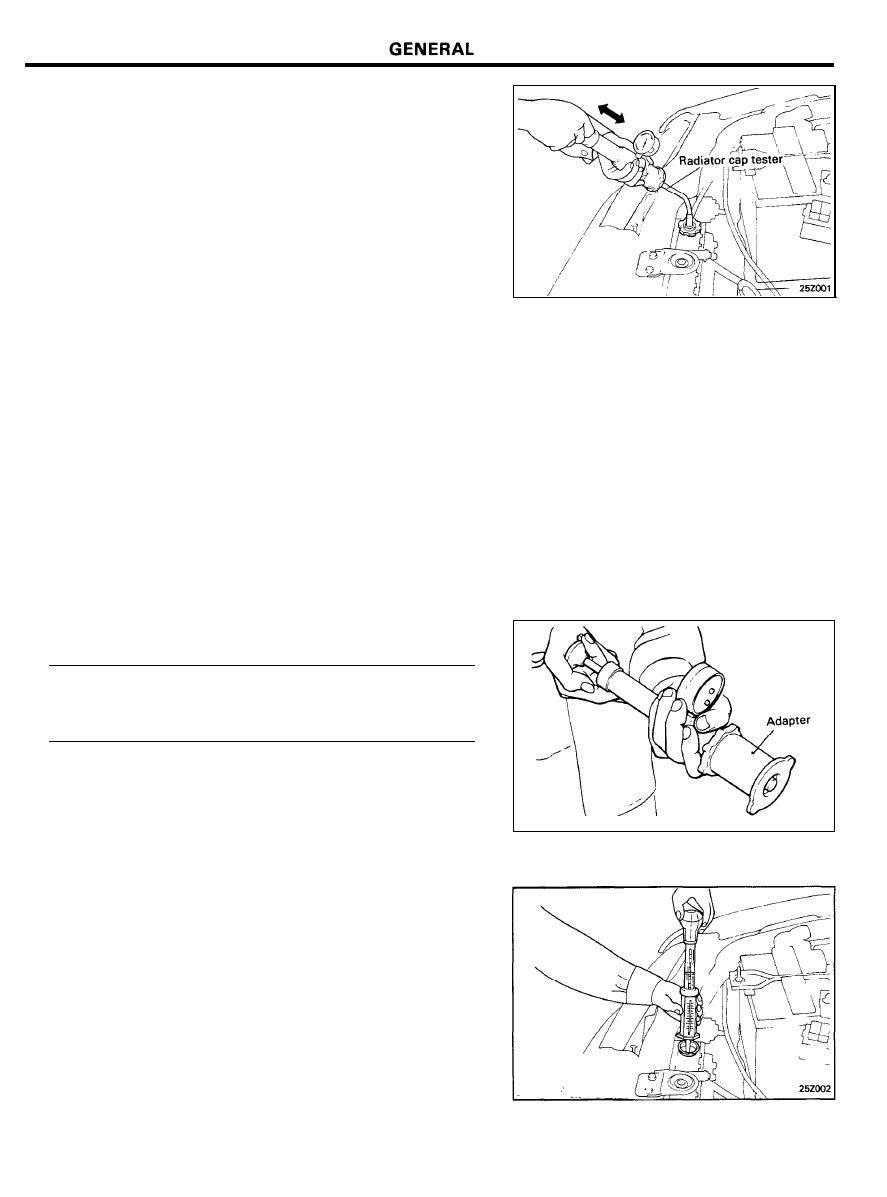
3. Install a radiator cap tester to the radiator filler neck and
apply 150 kPa (21 psi, 1.53 kg/cm*) pressure. Hold for two
minutes in that condition, while checking for leakage from
the radiator, hose, or connection.
CAUTION
Radiator coolant may be extremely hot. Do not open the
system while hot, or scalding water could spray out
causing personal injury. Allow the vehicle to cool before
servicing this system.
Be sure to completely clean away any moisture from the
places checked.
When the tester is removed, be careful not to spill any
coolant from it.
Use care, when installing and removing the tester. When
testing, do not distort the filler neck of the radiator.
4. If there is leakage, repair or replace the appropriate part.
RADIATOR CAP PRESSURE TEST
1. Use an adapter to attach the cap to the tester.
2.
Increase the pressure until the indicator of the gauge stops
moving.
Limit . . . . . . . . . . . . . . . . . . . . . . 65 kpa (9.2 psi, 0.66 kg/cm
2
)
Main valve opening pressure . . . . . . . . . . . . . . . . . . . . . . . . . . .
81.4-108 kPa (11.8-15.6 psi, 0.83-1.10 kg/cm
2
)
3.
Check that the pressure level is maintained at or above the
limit.
4. Replace the radiator cap if the reading does not remain at
or above the limit.
NOTE
Be sure the cap is clean before testing. Rust or other
foreign material on the cap seal will cause an incorrect
indication.
SPECIFIC GRAVITY TEST
1. Measure the specific gravity of the coolant with a
hydrometer.
2. Measure the coolant temperature, and calculate the
concentration from the relation between the specific gravity
and temperature, using the following table for reference.
2 5 - 5
GENERAL
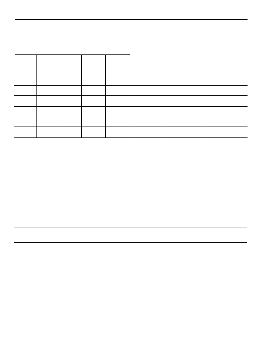
Relation Between Coolant Concentration and Specific Gravity
The following table is applicable only to the specified HIGH QUALITY ETHYLENE GLYCOL (ANTIFREEZE) COOLANT
Coolant temperature °C (°F) and specific gravity
Freezing
Safe operating
Coolant
temperature
temperature
concentration
10 (50)
20 (68)
30 (86)
40 (104)
50 (122)
°C (°F)
°C (°F)
(Specific volume)
1.054
1.050
1.046
1.042
1.036
- 1 6 ( 3 . 2 )
- 1 1 (12.2)
30%
1.063
1.058
1.054
1.049
1.044
- 2 0 ( - 4 )
- 1 5 ( 5 )
35%
1.071
1.067
1.062
1.057
1.052
- 2 5 ( - 1 3 )
- 2 0 ( - 4 )
40%
1.079
1.074
1.069
1.064
1.058
- 3 0 ( - 2 2 )
- 2 5
( - 1 3 )
45%
1.087
1.082
1.076
1.070
1.064
- 3 6 ( - 3 2 . 8 )
- 3 1
( - 2 3 . 8 )
50%
1.095
1.090
1.084
1.077
1.070
- 4 2 ( 4 4 )
- 3 7
( - 3 5 )
55%
1.103
1.098
1.092
1.084
1.076
- 5 0 ( - 5 8 )
- 4 5
( 4 9 )
60%
Example
The safe operating temperature is -15°C (5°F) when the measured specific gravity is 1.058 at coolant temperature
of 20°c (68°F).
CAUTION
If the concentration of the coolant is below 30%. the anti-corrosion property will be adversely affected. In
addition, if the concentration is above 60%. both the anti-freeze and engine cooling properties will decrease,
affecting the engine adversely. For these reasons, be sure to maintain the concentration level within the specified
range.
Do not mix different brands of coolant.
RECOMMENDED COOLANT
Antifreeze
ETHYLENE GLYCOL
BASE FOR ALUMINUM
Mixture ratio of antifreeze in coolant
50%
2 5 - 6
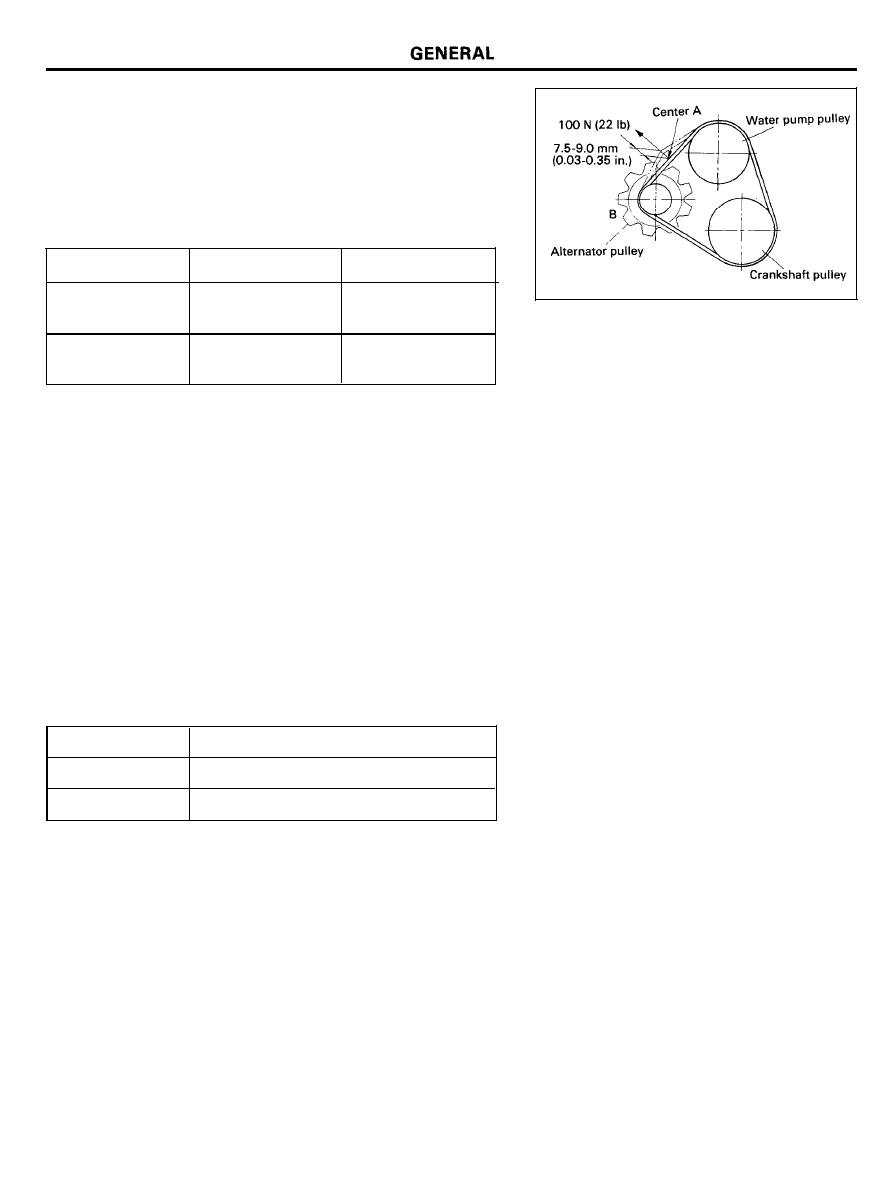
DRIVE BELT TENSION DEFLECTION
CHECK AND ADJUSTMENT
Drive Belt Measurement And Adjustment
To meet specifications measure belt deflection at point A. If not
within specifications loosen the alternator (point B) and adjust
in or out to meet specifications in the chart below.
Deflection
Tension (T)
Installed new belt
Installed used belt
5 . 5 - 7 . 0 m m
8.0 mm
(0.22-0.28 in.)
(0.31 in.)
5 0 - 7 0 k g
40 kg
(110-154 lb)
(88 lb)
Length Checkup of Drive Belt
After engine is driven, belt length is to be satisfied following
value when belt is measured as above method (cold engine
temperature of engine cooling water is above 20°C (68°F).
Drive belt check up
Deflection
7.0-8.2 mm (0.28-0.32 in.)
Tension (T)
35-50 kg (77-110 lb)
2 5 - 7
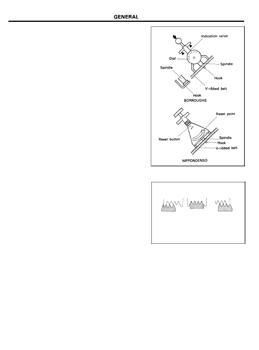
USAGE OF TENSION GAUGE
Using Tension Gauge
BORROUGHS BT-33-73F Type
NIPPONDENSO BTG-2 Type
Measuring Method
1.
Press down on the tension gauge handle and insert the belt
between the spindle and hook of the gauge.
2.
Release the handle and read the measurement on the gauge.
NOTE
1. A belt which has been in operation for 5 minutes or more,
must be adjusted to the used belt specifications.
2. Check to see that the belt is installed correctly, as shown
in the illustration.
3. A loose belt will produce a high-pitched squealing noise.
4. A belt that is too tight will damage the alternator and
water pump bearings.
Incorrect
Correct
Incorrect
2 5 - 8
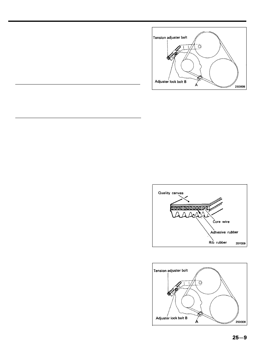
COOLING SYSTEM
DRIVE BELT AND PULLEY
Removal
1.
Loosen the alternator support bolt “A” and the belt tension
adjuster lock bolt “B”.
2. Rotate the adjuster bolt counterclockwise to relieve belt
tension, and remove the belt.
3.
Remove the water pump pulley bolts and remove the water
pump pulley.
Tightening torque
Alternator support bolt A . . . . . . . . . . . . . . . . . . . . . . . . . . . . .
20-25 Nm (200-250 kg.cm, 14-18 lb.ft)
Adjuster lock bolt B . . . . . . . . . . . . . . . . . . . . . . . . . . . . . . . . . .
12-15 Nm (120-150 kg.cm, 9-11 lb.ft)
Inspection
Check the following items and replace if defective.
1. Check the surface for damage, peeling or cracks.
2. Check the belt surface for oil or grease.
3. Check the rubber for worn or hardened areas.
4. Check the surface of the pulley for cracks or damage.
Installation
1. Install the water pump pulley to the water pump pulley
bracket and tighten the bolts firmly.
2.
After installing the belt, adjust the belt tension. See “DRIVE
BELT TENSION DEFLECTION CHECK AND ADJUSTMENT”.
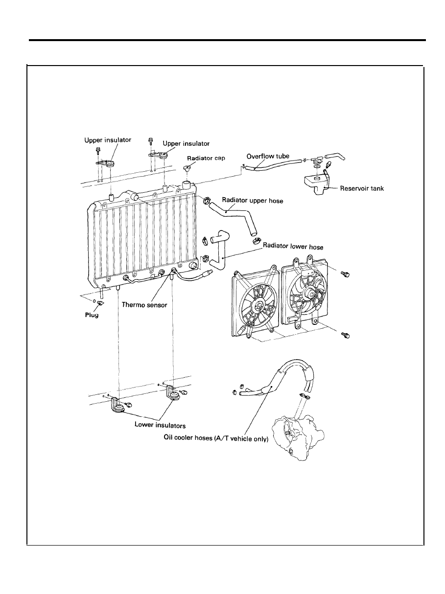
RADIATOR
RADIATOR
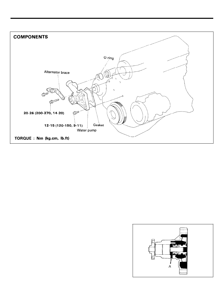
COMPONENTS
2 5 - 1 0
RADIATOR
REMOVAL
1.
2.
3.
4.
5.
Disconnect the fan motor plug.
Set the warm water flow control knob of the heater control
to the hot position.
Loosen the radiator drain plug to drain coolant.
Disconnect the upper and lower hose, and the overflow tube.
For vehicles with an automatic transaxle, disconnect the oil
cooler hoses from the automatic transaxle.
CAUTION
Plug the ends of the oil cooler hoses and the automatic
transaxle port to prevent the transaxle fluid from spilling
out and foreign material from getting in.
6.
Remove the radiator mounting bolts.
7.
Remove the radiator together with the fan motor.
8.
Remove the fan motor from the radiator.
INSPECTION
1. Check the radiator for bent, broken or plugged fins.
2. Check the radiator for corrosion, damage, rust or scale.
3.
Check the radiator hoses for cracks, damage or deterioration.
4. Check the reservoir tank for damage.
5.
Check the radiator cap spring for damage. Pressure test the
cap using a cooling system checker.
6. Check the radiator cap seal for cracks or damage.
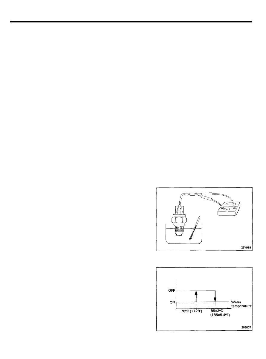
7. Check for continuity with the thermo sensor in hot water.
Continuity at 85 ± 3°C (185 ± 5.4°F)
No continuity at 78°C (172°F) or more
NOTE
Immerse the thermo sensor in hot water up to the
mounting threads to check for continuity.
2 5 - 1 1
RADIATOR
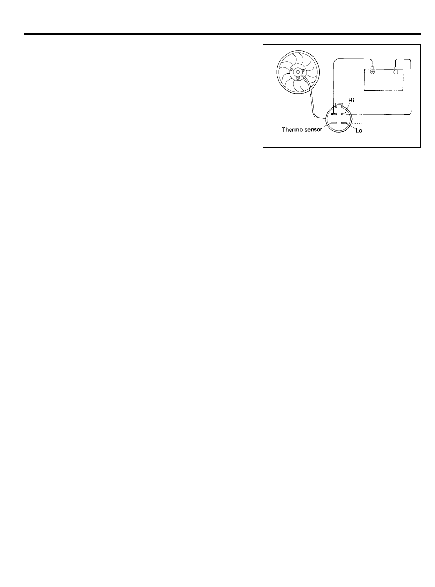
Radiator Fan Motor
1.
Check to be sure that the radiator fan rotates when battery
voltage is applied between the terminals (as shown in the
figure).
2.
Check to see that abnormal noises are not produced while
the motor is turning.
INSTALLATION
1. Fill the radiator and reservoir tank with a fresh coolant
mixture.
2.
Run the engine until the coolant has warmed up enough so
that the thermostat valve opens, and then stop the engine.
3. Remove the radiator cap, pour in the coolant until it is up
to the filler neck of the radiator, and then fill the reservoir
tank to the upper level.
4.
Check to be sure that there is no leakage from the radiator,
hoses or connections.
2 5 - 1 2
WATER PUMP
WATER PUMP
REMOVAL
1. Drain the coolant and disconnect the radiator outlet hose
from the water pump.
2. Remove the drive belt and water pump pulley.
3.
Remove the timing belt covers and the timing belt tensioner.
4. Remove the water pump mounting bolts and remove the
alternator brace.
5.
Remove the water pump assembly from the cylinder block.
INSPECTION
1. Check for excessive corrosion, cracks, damage, or wear.
Replace the water pump assembly if necessary.
2.
Check the bearing for damage, abnormal noise, and sluggish
rotation. Replace the water pump assembly if necessary.
3.
Check for water leakage. If water leaks from hole “A”, the
seal unit is defective. Replace water pump assembly.
2 5 - 1 3
W A T E R P U M P
INSTALLATION
1.
Clean the gasket surfaces of the water pump body and the
cylinder block.
2.
Install the new O-ring onto the groove on the front end of
the water pipe. Wet the O-ring with water. Do not apply oil
or grease.
3.
Install a new water pump gasket and water pump assembly.
Tighten the bolts to the specified torque.
Tightening torque
Water pump to cylinder block
Head mark “4” bolt . . . . . . . . . . . . . . . . . . . . . . . . . . . . . . . . . .
12-14 Nm (120-150 kg.cm, 9-11 lb.ft)
Head mark “7” bolt . . . . . . . . . . . . . . . . . . . . . . . . . . . . . . . . . .
20-26 Nm (200-270 kg.cm, 14-20 lb.ft)
4.
Install the timing belt tensioner and the timing belt. Adjust
the timing belt tension. Then install the timing belt covers.
See “Engine”, for detailed procedure.
5.
Install the water pump pulley and drive belt. Then adjust the
belt tension.
6. Refill with fresh coolant mixture.
7. Run the engine and check for leaks.
2 5 - 1 4
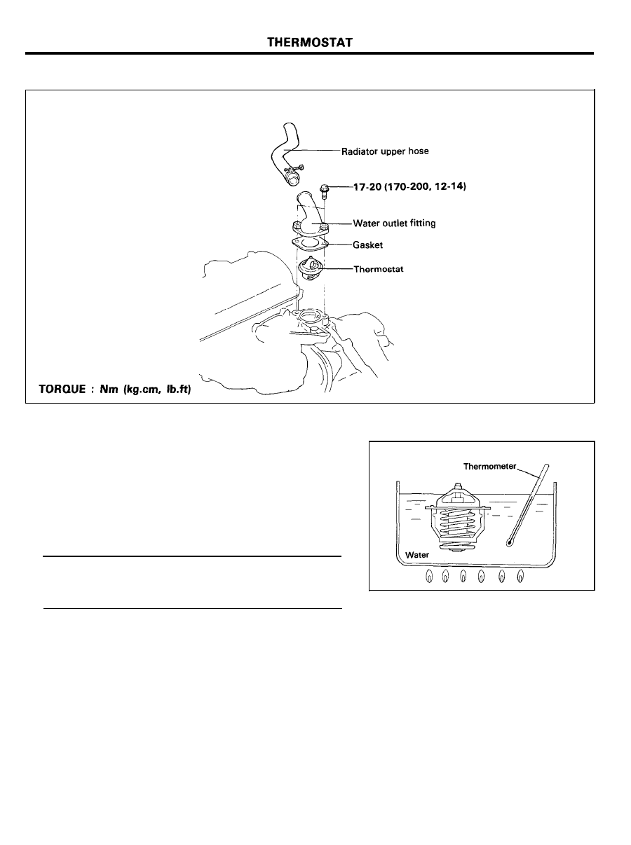
THERMOSTAT
COMPONENTS
REMOVAL AND INSPECTION
1. Drain the coolant down to the thermostat level or below.
2. Remove the water outlet fitting and gasket.
3. Remove the thermostat.
4. Heat the thermostat as shown in the illustration.
5. Check to see if the valve operates properly.
6.
Determine temperature at which the valve begins to open.
Valve opening temperature . . . . . . . 88±1.5°C (190.4±2.7°F)
Full opening temperature . . . . . . . . . . . . . . . . . 100°C (212°F)
Valve lift (at full open) . . . . . . . . . 8 mm (0.31 in.) or more
INSTALLATION
1. Make sure that the flange of the thermostat is correctly
seated in the socket of the thermostat housing. If the
thermostat is installed in the wrong direction, bottom of
thermostat will touch the rib inside the intake manifold,
making it impossible to seat the flange.
2. Install a new gasket and the water outlet fitting.
3. Refill with fresh coolant mixture.
2 5 - 1 5
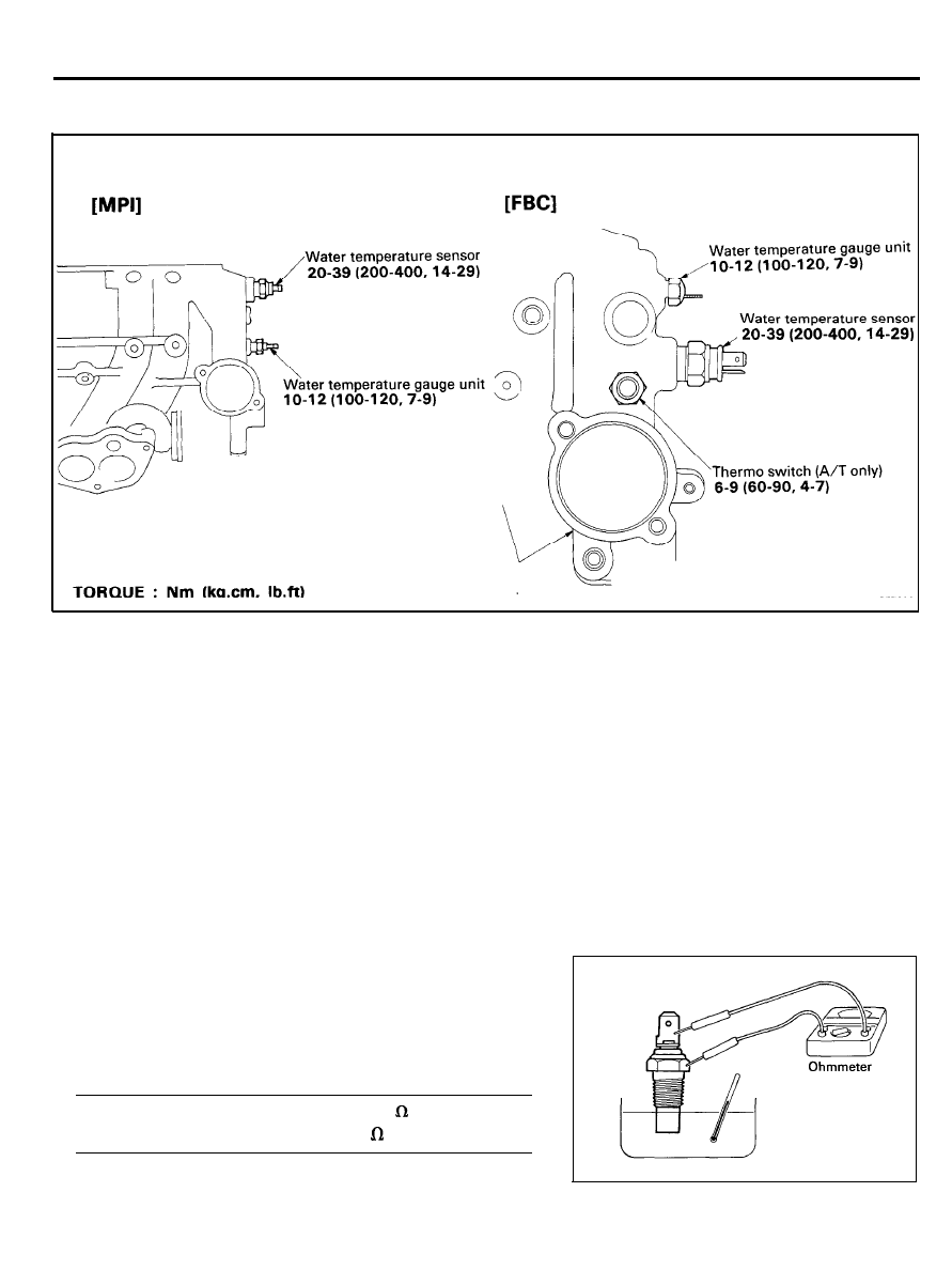
WATER TEMPERATURE GAUGE UNIT, SENSOR
WATER TEMPERATURE GAUGE UNIT, SENSOR
COMPONENTS
REMOVAL
1. Drain the coolant down to the gauge unit level or below.
2.
Disconnect the battery ground cable and the engine harness.
3. Remove the water temperature gauge unit, sensor.
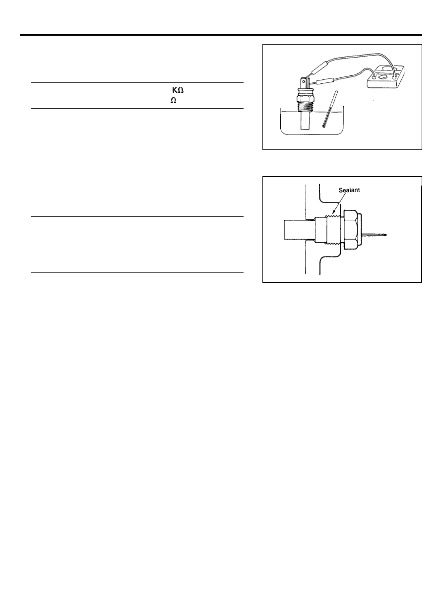
INSPECTION
Water Temperature Gauge Unit
1.
Heat the water temperature gauge unit by submerging it in
hot water.
2. Check that the resistance is within the specified range.
Resistance . . . . . . . . . . . . . . 90.5-117.5 at 70°C (158°F)
21.3-26.3 at 115°C (239°F)
2 5 - 1 6
WATER TEMPERATURE GAUGE UNIT, SENSOR
Water Temperature Sensor
1. Heat the sensor by submerging it in hot water.
2. Check that the resistance is within the specified range.
Resistance . . . . . . . . . . . . . . . . 2.21-2.69
at 20°C (68°F)
264-328
at 80°C (176°F)
INSTALLATION
1.
Apply sealant to the threaded portion of the sensor, gauge
unit and tighten to the specified torque.
Tightening torque
Water temperature gauge unit . . . . . . . . . . . . . . . . . . . . . . . .
10-12 Nm (100-120 kg.cm, 7.2-8.7 lb.ft)
Water temperature sensor . . . . . . . . . . . . . . . . . . . . . . . . . . . .
20-39 Nm (200-400 kg.cm, 14-29 lb.ft)
2.
Connect the harness to the water temperature gauge unit,
temperature sensor.
3. Connect the battery ground cable.
4. Refill with a fresh coolant mixture.
2 5 - 1 7
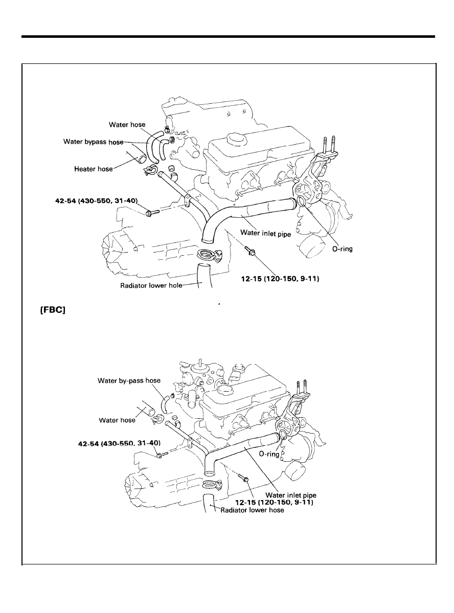
WATER HOSE AND PIPE
WATER HOSE AND PIPE
COMPONENTS
[MPI]
TORQUE : Nm (kg.cm, lb.ft)
2 5 - 1 8
WATER HOSE AND PIPE
INSPECTION
Check the water pipe and hose for cracks, damage, or
restrictions. Replace if necessary.
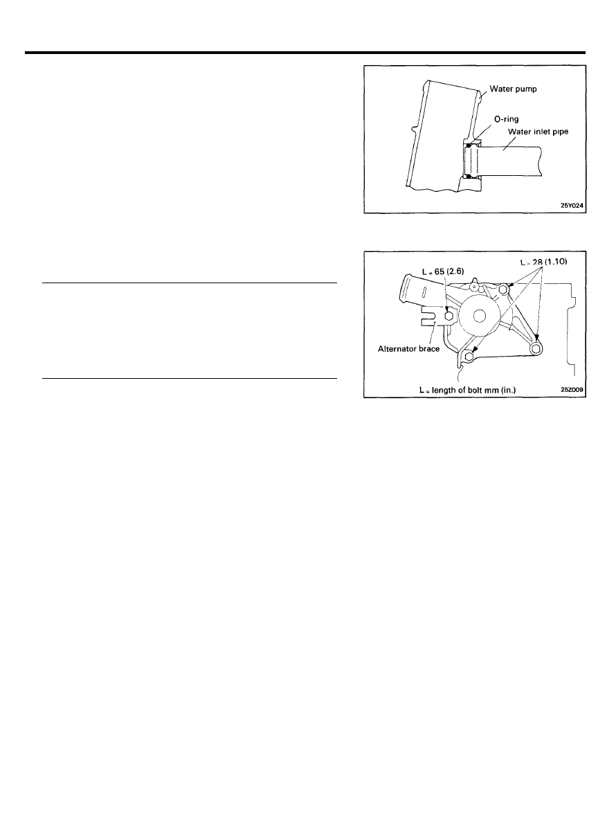
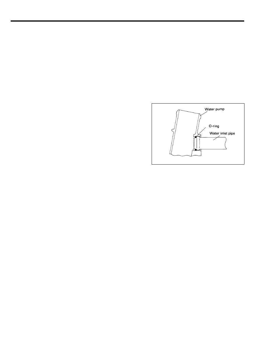
INSTALLATION
Fit the O-ring in the groove provided at the water inlet pipe end.
Wet the O-ring with water and inset the water inlet pipe.
NOTE
1. Do not apply oils or greases to the water pipe O-ring.
2. Keep the water pipe connections free of sand, dust, etc.
3. Insert the water pipe until its bottoms.
2 5 - 1 9
Wyszukiwarka
Podobne podstrony:
05 cooling system
05 Fuel System
05 06 Systemy resztowe
EVAPORATIVE COOLING SYSTEMS
5 Cooling System
2014 05 24 Systemy Zarzadzania wykladyid 28543
Popular Mechanics Flushing Your Cooling System
Popular Mechanics Repairing Cooling System Leaks
COOLING SYSTEM
05 Fuel System
Automotive Engine Lubrication & Cooling Systems
05 USA system szkolnictwa
G 2 0 DOHC Cooling System Repair doc
general cooling system servicing
Tab6 M73TU&M62TU Cooling Systems
więcej podobnych podstron