
302 Enzo Drive
San Jose CA 951
38 USA
ph 1 408 363 8000
fax 1 408 363 8313
info@sunrisetelecom.com
www.sunrisetelecom.com
… a step ahead
Technology Series
Introduction to Signaling System No. 7
Publication Number TEC-GEN-003 Rev. B
2
© 2001 Sunrise Telecom Incorporated
Introduction to Signaling System No. 7
1 INTRODUCTION
Signaling refers to a protocol or language used by the
Network Elements (NEs) to exchange information, thus
providing and maintaining services. The name "signal-
ing" derives from former systems that used actual
signals (pulses, DTMF, or MF tones) as a means of
communication. Today’s modern signaling systems
exchange complex digital messages between Network
Elements. Out-of-band signaling refers to systems that
carry the signaling messages in a different (dedicated)
path than that of the voice and data traffic.
Signaling System No. 7 (SS7) is a common channel
signaling system developed by ITU-T (formerly CCITT) in
response to a demand for more features and integrated
data services. It is a high-speed, out-of-band signaling
system based on ITU-T recommendation Q.700 series
that has become a global standard for telecommunica-
tions. SS7 defines the architecture, procedures, and
protocols for information exchange over digital
channels. It is designed to support call setups, routing,
billing, database information, and special service
functions for PSTNs. The ITU-T definition of SS7 allows
for national variants such as ANSI, Bellcore (North
America), ETSI (used in Europe), and several country-
dependant variants.
One timeslot on the signaling T1 (or E1) link is used for
transmission of SS7 messages. Applications have the
flexibility to define any of the 24 (or 31) timeslots as a
signaling channel. This means one channel is assigned
solely for sending the signaling information, whether
the system has one bearer channel or multiple bearer
channels. In order to support this architecture, a new
protocol was developed which is a variation of data
packet switching. The signaling channel packets
contain framing words, checksums, addresses, and
information. The order of these packets is well defined
and flexible in terms of user requirements.
Examples of some applications supported by SS7 are:
• PSTN
• ISDN (Voice and Data)
• Interaction with Network Databases and Service
Control Points for service control
• Mobile Services
• Operations Administration and Maintenance of
Networks
SS7 networks provide the following functionality:
• Basic call setup, management, billing, and release
• Enhanced call features such as call waiting, call
forwarding, calling party name/number display/
restriction/rejection, and three-way calling
• Handling congestion and priorities
• Wireless services such as PCS, wireless roaming, and
mobile subscriber authentication
• Local number portability (LNP)
• Toll-free and toll services
• Exchange of database information between NEs
• Network management for efficient and secure
worldwide telecommunications
Residential
ISDN-BRI
PRI
SCP
SCP
A
A
A
A
E
E
A
A
A
B
B
C
C
C
D
D
D
D
F
A
PBX
STP
STP
STP
STP
STP
STP
SSP
SSP
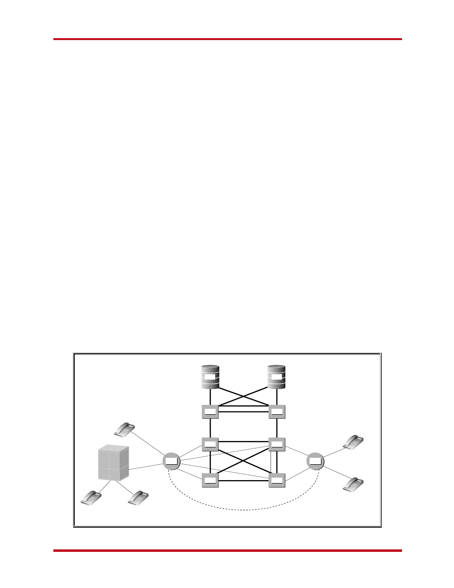
Figure 1 SS7 Network Structure

3
© 2001 Sunrise Telecom Incorporated
Introduction to Signaling System No. 7
2 SIGNALING NETWORK ARCHITECTURE
2.1 Signaling Links
SS7 messages are exchanged between Network Ele-
ments over one or more signaling links. Signaling
occurs out-of-band on dedicated channels rather than
in-band on voice channels. Advantages of out-of-band
over in-band signaling include:
• Speed: Faster call setup times (compared to in-band
signaling using MF signaling tones)
• Efficiency: More efficient use of voice circuits,
especially on international or long distance calls,
where the voice channel is only occupied when the
called party is available
• Flexibility: Complex messages, instead of simple
signals, allow SS7 to offer more services
• Management: Support signaling between NEs
without voice trunks (database systems, for example).
• Control: Improved control over fraudulent network
usage.
Types of Signaling Links
The SS7 network structure allows different types of
connections between SPs. These links are logically
organized by types (A to F), according to their use in the
network. All links are identical (56 or 64 kbps bi-
directional data links) and support the same lower layer
of the protocol.
A Link: An Access link connects a signaling end point or
source point (for example, SCPs or SSPs) to an STP.
Only messages originating from or destined to the
signaling end point are transmitted on an "A" link.
B Link: A Bridge link connects STPs. Typically, quads of
B links interconnect primary STPs of one network to
primary STPs of another network. The distinction
between B and D links is rather arbitrary. For this
reason, such links may be referred to as B/D links.
C Link: A Cross link connects STPs performing identical
functions into a mated pair; they are used to
enhance the reliability of the signaling network. A C
link is used only when an STP has no other route
available to a destination signaling point due to link
failures. Note that SCPs may also be deployed in
pairs to improve reliability, unlike STPs. However,
signaling links do not interconnect mated SCPs.
D Link: A Diagonal link connects pairs of STPs at
different hierarchical levels (for example, a secondary
[local or regional] STP pair to a primary [inter-
network gateway] STP pair in a quad-link configura-
tion). Secondary STPs within the same network are
connected via a quad of D links.
E Link: An Extended link connects an SSP to an
alternate STP to provide an alternate signaling path.
E links are not usually provisioned unless the benefit
of a marginally higher degree of reliability justifies
the added expense.
F Link: A Fully associated link connects two signaling
end points (for example., SSPs and SCPs). F links are
not usually deployed in networks with STPs, because
they bypass the security features provided by the
STPs. In networks without STPs, F links directly
connect signaling points.
2.2 Signaling Points (SP)
Each signaling point in the SS7 network is uniquely
identified by a numeric point code (PC). Point codes are
carried in signaling messages exchanged between
signaling points to identify the origination (OPC) and
destination (DPC) of each message. Each signaling
point uses a routing table to select the appropriate
signaling path for each message.
Types of Signaling Points
Service Switching Points (SSP) are switches (exchanges
or central offices) with SS7 software that originate,
terminate, or tandem calls. An SSP sends signaling
messages to other SSPs to setup, manage, and release
voice circuits required to complete a call. An SSP
may also send a query message to a centralized
database (SCP) to determine how to route a call (for
example, toll-free calls).
Signaling Transfer Points (STP) are packet switches that
route network traffic between signaling points. An
STP routes each incoming message to an outgoing
signaling link based on routing information con-
tained in the SS7 message. Since STPs act as
network hubs, they improve the utilization of the
SS7 network by eliminating the need for direct links
between signaling points. STPs also offer specialized
routing functions for toll-free 800 numbers, calling
card numbers, or mobile subscriber identification
numbers. An STP may also be used to screen the
messages exchanged with other networks.
Service Control Points (SCP) are databases that provide
information necessary for advanced call-processing
capabilities. STPs are usually deployed in mated pair
configurations in separate physical locations as a
backup system. Traffic is shared across all links, so if
one of the links fails, the signaling traffic is rerouted
over another link. The SS7 protocol provides both
error correction and retransmission capabilities to
allow continued service in the event of signaling
point or link failures.
4
© 2001 Sunrise Telecom Incorporated
Introduction to Signaling System No. 7
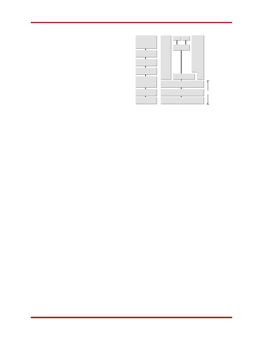
3 SS7 PROTOCOL LAYERS
(ARCHITECTURE)
Like the OSI reference model, the hardware and
software functions of the SS7 protocol are also divided
into functional layers. Initial SS7 architecture was
based on circuit-related control telephony, but as new
requirements have emerged, SS7 keeps evolving. It now
allows non-circuit related information transfer, for
example.
3.1 Message Transfer Part (MTP)
The MTP is divided into three levels:
• Signaling Data Link functions: Define the physical,
electrical, and functional characteristics of the digital
signaling link. Defined physical interfaces include,
DS1 (1.544 Mbps), E1 (2.048 Mbps), V.35 (64 kbps),
DS0 (64 kbps), and DS0A (56 kbps).
• Signaling Link functions: Define the functions and
procedures to ensure that messages are reliably
transmitted across a signaling link. They implement
flow control, message sequence validation, and error
checking. When an error occurs on a signaling link,
the messages are retransmitted.
• Signaling Network functions: Define those transport
functions and procedures that are common to and
independent of individual signaling links. They
provide message routing between signaling points in
the SS7 network. They also re-route traffic away
from failed links and signaling points, and control
traffic when congestion occurs.
3.2 Signaling Connection Control Part
(SCCP)
Provide additional functions to the MTP, to support
connectionless and connection-oriented network
services and Global Title Translation (GTT). SCCP
provides subsystem numbers to allow messages to be
addressed to specific applications or subsystems at
specified signaling points. SCCP is used as the transport
layer for TCAP-based services.
GTT: Adds the ability to perform incremental routing
and frees the originating signaling point of having to
know every possible destination. A global title is an
address (an 800 number, calling card number, or
mobile subscriber identification number) which is
translated by SCCP into a destination point code and
subsystem number. A subsystem number uniquely
identifies an application at the destination signaling
point. SCCP is used as the transport layer for TCAP-
based services.
3.3 Telephone User Part (TUP)
Defines the international telephone call control
signaling functions for basic call setup and release. TUP
was an earlier implementation of SS7 and does not
allow for data type applications.
3.4 ISDN User Part (ISUP)
Defines the protocol used to setup, manage, and release
trunk circuits that carry voice and data between SSPs.
ISUP is used for both ISDN and non-ISDN calls. How-
ever, calls that originate and terminate at the same
switch do not use ISUP signaling.
3.5 Transaction Capabilities (TC)
Provides the means to establish non-circuit related
communications between two SPs.
Transaction Capabilities Applications Part (TCAP):
Supports the exchange of non-circuit related data
between applications across the SS7 network using
the SCCP connectionless service as a transport.
Queries and responses sent between SSPs and SCPs
are carried in TCAP messages. In mobile networks
(IS-41 and GSM), TCAP carries Mobile Application
Part (MAP) messages sent between mobile switches
and databases to support user authentication,
equipment identification, and roaming.
3.6 Operations, Maintenance and
Administration Part (OMAP) and ASE
OMAP defines messages and protocols that assist the
administration of SS7 networks. OMAP services may be
used to verify network routing databases and to
diagnose link problems. Application Service Element
(ASE) is a module or portion of a protocol in the
application layer 7 of the OSI (Open Systems Intercon-
nection) protocol stack. Several ASEs are usually
combined to form a complete protocol.
Applications
OSI Model
SS7 Model
Data Link
Physical
Signaling Network
Signaling Data Link
Network
Transport
Sessions
Presentation
TUP
TCAP
SCCP
OMAP
GSM
ISUP
Signaling Link
MTP
Figure 2 OSI and SS7 layers
5
© 2001 Sunrise Telecom Incorporated
Introduction to Signaling System No. 7
4 MESSAGE TRANSFER PART (MTP)
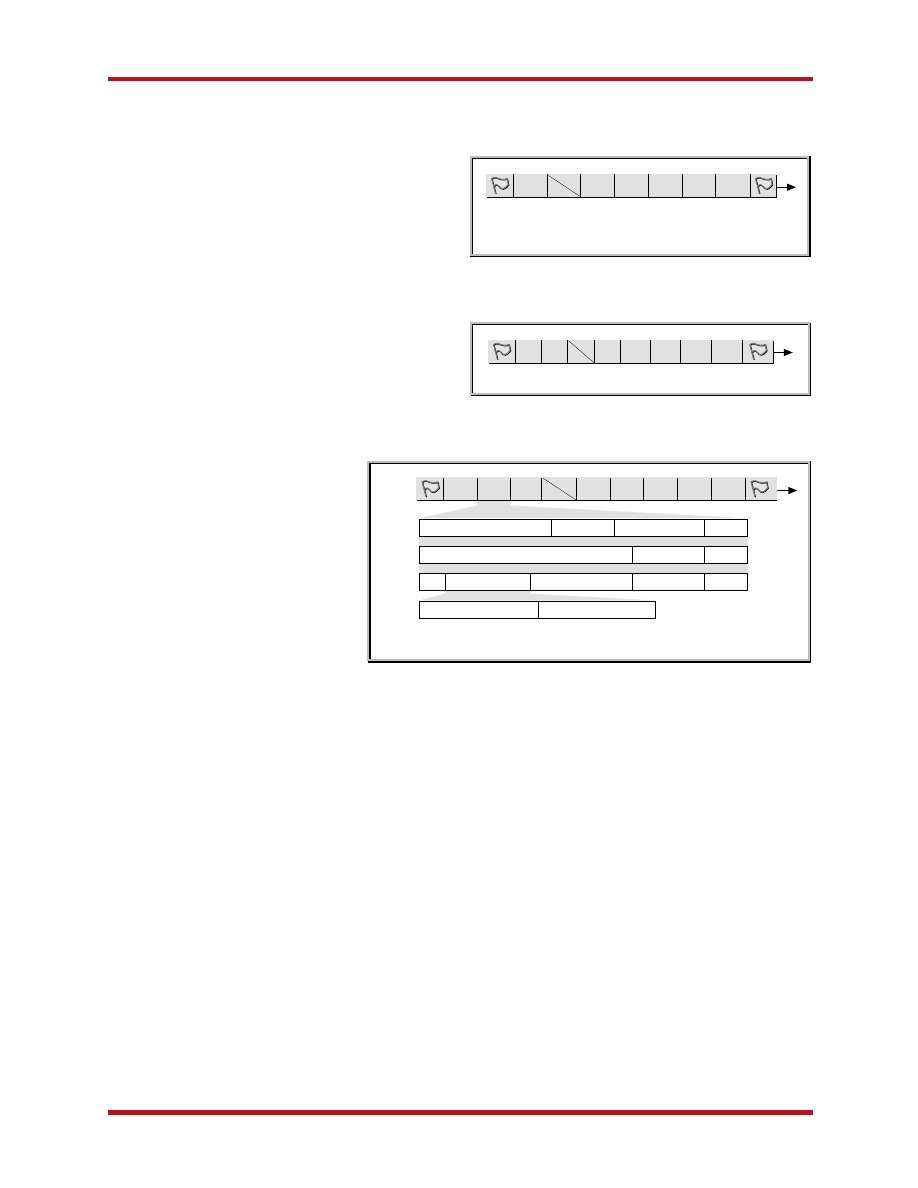
4.1 Signaling Link Messages
There are three types of signal units (SUs): Fill-In Signal
Units (FISUs), Link Status Signal Units (LSSUs), and
Message Signal Units (MSUs).
Fill-In Signal Units (FISU) operate when there is no
other SU traffic present. FISUs are transmitted
continuously on a signaling link in both directions to
keep the link alive and aligned. They carry a
checksum (CK) so that signaling link quality is
continually checked by the SPs at each end of the
link (see Figure 3).
Link Status Signal Units (LSSU) are used to exchange
link status information between the SPs at each end
of a link. They are used to control link alignment and
to give status of a signaling point to the remote
signaling point (see Figure 4).
Message Signal Units (MSU) are the
containers that carry TUP, ISUP, and
SCCP protocol messages (within the
SIF). They carry all call control,
database query and response,
network management, and network
maintenance data; there are addi-
tional specialized functions pertain-
ing to mobile cellular applications.
MSUs have a routing label that
allows an originating signaling point
to send information to a destination
signaling point across the network
(see Figure 5).
Flag (0111 1110) indicates the beginning
of a new signal unit and implies the end of the
previous signal unit (if any). False flags are removed
before transmitting the message by adding a zero
after any sequence of five ones (bit stuffing).
BSN (Backward Sequence Number) acknowledges the
receipt of signal units by the remote signaling point.
The BSN contains the sequence number of the signal
unit being acknowledged. Every single message
needs to be acknowledged by means of BSN.
BIB (Backward Indicator Bit) is used for error recovery
and indicates a negative acknowledgment by the
remote signaling point when inverted.
FSN (Forward Sequence Number) contains the sequence
number of the signal unit.
FIB (Forward Indicator Bit) is used in error recovery; it
also transmits when the originating signaling point
receives a negative acknowledgment. It retransmits
all forward messages, beginning with the corrupted
message; in this instance, the FIB is inverted.
SIO (Service Information Octet) contains the subservice
field and service indicator.
– Subservice Field contains the network indicator
(national or international) and the message
priority. Message priority is considered only under
congestion conditions. Low priority messages may
be discarded during periods of congestion.
Signaling link test messages receive a higher
priority than call setup messages.
– Service Indicator specifies the MTP user (TUP, ISUP,
DUP, SCCP, SNM, MTNE).
SIF (Signaling Information Field) contains the routing
label and signaling information (i.e., SCCP, TCAP, and
ISUP message data). LSSUs and FISUs contain neither
a routing label nor an SIO as they are sent between
two directly connected signaling points. See Figure 6
on next page.
CK (Check bits) is a CRC value used to detect and
correct data transmission errors.
CK
LI
FIB
FSN
BIB
BSN
CK:
Check bits
FSN:
Forward Sequence Number
LI:
Length Indicator
BIB:
Backward Indication Bit
FIB:
Forward Indicator Bit
BSN:
Backward Sequence Number
CK
SF
LI
FIB FSN BIB BSN
SF:
Status Field
SIF:
Signaling Information Field
SIO:
Service Information Octet
MSU
TUP
ISUP
SCCP
TCAP
Message Information Element Message Type
Message Group
Label B
Message Information Element
Message Type
Label C
EOP User Message/Data SCCP Message Header
Message Type
Label D
Component Portion
Transaction Portion
CK
SIF
SIO
LI
FIB
FSN
BIB
BSN
Figure 3 FISU message structure
Figure 4 LSSU message structure
Figure 5 MSU message structure
6
© 2001 Sunrise Telecom Incorporated
Introduction to Signaling System No. 7
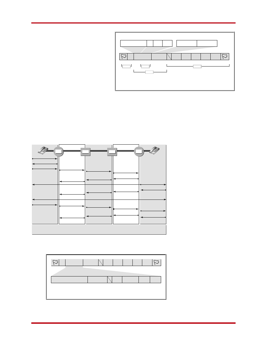
4.2 Signaling Network
The signaling network provides message
routing between SPs based on the routing
label in the SIF. It re-routes traffic away from
failed links and signaling points and controls
traffic when congestion occurs.
Point codes (OPC and DPC) are hierarchical
numeric addresses that identify each
signaling point in the SS7 network. Ad-
dresses are required so that a node can
exchange messages with other SPs that
are not connected via a physical link. A
PC address can be 14-bits or 24-bits long,
depending on the standard, and contains
three identifiers (Network, Cluster, and
Node addresses). ITU-T point codes are
pure binary numbers that identify the zone,
area/network, and SP identification num-
bers.
SLS:
Signaling Link Selection
OPC:
Originating Point Code
DPC:
Destination Point Code
CK
SIF
SIO
LI
FIB
FSN
BIB
BSN
SLS
User Part or
Network Management
OPC
DPC
D C B A
Subservice Field
D C B A
Service Indicator
8
16
Nx8 + 32
Nx8
4
14
14
8
2
6
1
7
1
7
8
Layer 2
Layer 4
Layer 3
Layer 2
IAM
IAM
IAM
REL
REL
REL
ACM
ACM
ACM
ANM
ANM
ANM
RLC
RLC
RLC
(Voice path)
Speech (over voice path)
Talk
On-hook
Off-hook
Digits
Dial Tone
Ringing Tone
Ring
Off-hook
Talk
Silence or tone
On-hook
IAM:
Initial Address Message
REL: Release
Message
ACM:
Address Complete Message
RLC:
Release Complete Message
ANM:
Answer Message
STP
STP
SSP
SSP
CIC: Circuit Identification Code
CK
SIF
SIO
LI
FIB
FSN
BIB
BSN
MSG INFORMATION MSG TYPE
CIC
SLS/SLC
OPC
DPC
Variable length
8 bits
4
12/14
4/5
14/24
14/24
SLS: Signaling Link Selection
SLC: Signaling Link Code
5 ISDN USER PART (ISUP)
ISUP defines the protocol and procedures used to set
up, manage, and release trunk circuits that carry voice
and data calls over the public switched telephone
network. It is used for both ISDN
and non-ISDN calls. Calls that
originate and terminate at the
same switch do not use ISUP
signaling.
5.1 ISUP Message Structure
In an ISUP message, the SIF
contains the routing label
followed by a 14-bit (ANSI) or 12-
bit (ITU) circuit identification
code (CIC). The CIC indicates the
trunk circuit reserved by the
originating switch to carry the
call. The message type field (IAM,
ACM, ANM, REL, and RLC), which
defines the contents of the
remainder of the message, follows
the CIC. See Figure 8.
5.2 Initial Address Message
(IAM)
This contains call setup informa-
tion and is sent when the switch
needs to complete the circuit
between the calling party and
called party. An IAM contains the
called party number in the
mandatory variable part and may
contain the calling party name
and number in the optional part.
Figure 6 SIF and SIO field structure
Figure 7 Sample of basic ISUP call
Figure 8 ISUP message structure

7
© 2001 Sunrise Telecom Incorporated
Introduction to Signaling System No. 7
5.3 Address Complete Message (ACM)
ACM indicates that the called party is available and a
remote end of a trunk circuit has been reserved. The
originating switch responds to an ACM message by
connecting the calling party’s line to the trunk; this
completes the voice circuit from the calling party to the
called party. The calling party hears the ringing tone on
the voice trunk generated by the destination switch.
5.4 Answer Message (ANM)
When the called party answers, the destination switch
terminates the ringing tone and sends an Answer
Message (ANM) to the originating switch. The originat-
ing switch initiates billing after verifying that the
calling party’s line is connected to the reserved trunk.
5.5 Release Message (REL)
This indicates that the circuit is being released and
specifies a release cause. A REL is sent when either the
calling or called party "hangs up" the call (cause=16). A
REL is also sent in the backward direction if the called
party line is busy (cause=17) or if no channel is avail-
able (cause=34).
5.6 Release Complete Message (RLC)
Acknowledges the reception of REL from the remote
end of a trunk circuit and ends the call and billing cycle.
6 TRANSACTION CAPABILITIES
APPLICATION PART (TCAP)
Enables the deployment of advanced intelligent
network services by supporting non-circuit related
information exchange between signaling points using
the SCCP connectionless service. An SSP uses TCAP to
query an SCP to determine the routing numbers
associated with a dialed 800, 877, 888, or 900 numbers.
The SCP uses TCAP to return a response containing the
routing numbers, plus any error/reject messages, back
to the SSP. Calling card calls are also validated using
TCAP. When a mobile subscriber roams into a new
mobile switching center (MSC) area, the integrated
visitor location register requests service profile informa-
tion from the subscriber’s home location register (HLR).
This is accomplished using mobile application part
(MAP) information carried within TCAP messages.
A TCAP message is comprised of a transaction portion
and a component portion, described in detail in the
following section.
6.1 Transaction Portion
Contains the package type identifier. There are seven
package types:
• Unidirectional: Transfers components in one
direction and no reply is expected.
• Query with Permission: Initiates a transaction. The
destination node may end the transaction.
• Query without Permission: Initiates a transaction.
The destination node cannot end the transaction.
• Response: Ends the transaction. A response to a
query with permission may contain the routing
numbers associated with an 800 number.
• Conversation with Permission: Continues a transac-
tion. The destination node may end the transaction.
• Conversation without Permission: Continues a
transaction. The destination node cannot end the
transaction.
• Abort: Terminates a transaction due to an abnormal
situation.
The transaction portion also contains the Originating
Transaction ID and Responding Transaction ID fields.
These associate the transaction with a specific applica-
tion at the originating and destination SPs.
6.2 Component Portion
There are six kinds of components:
• Invoke (Last): Invokes an operation. For example, a
Query with Permission transaction may include an
Invoke (Last) component to request SCP translation
of a dialed 800 number. The component is the last
component in the query.
• Invoke (Not last): Similar to the Invoke (Last)
component, except that the component is followed
by one or more components.
• Return Result (Last): Returns the result of an
invoked operation. The component is the last
component in the response.
• Return Result (Not last): Similar to the Return Result
(Last) component, except that the component is
followed by one or more components.
• Return Error: Reports the unsuccessful completion
of an invoked operation.
• Reject: Indicates that an incorrect package type or
component was received.
Components include parameters which contain applica-
tion-specific data unexamined by TCAP.

8
© 2001 Sunrise Telecom Incorporated
Introduction to Signaling System No. 7
ANN
Answer Signal, No Charge (TUP)
ANM
Answer Message (ISUP)
ANSIAmerican National Standards I
nstitute
ANU
Answer Signal Unqualified (TUP)
ASE
Application Service Element
B
B link
Bridge Link
BELLCORE Bell Communication Research. Now
BIB
Backward Indicator Bit
BLA
Blocking Acknowledgement Signal (ISUP, TUP)
BLO
Blocking Signal (ISUP, TUP)
BSM
Backward Set-up Message (TUP)
BSN
Backward Sequence Number
C
C links
Cross Links
C7
Signaling System No.7. This is another
refer to SS7
CBA
Changeback Acknowledgement Signal (SNM/
CBD
Changeback Declaration Signal (SNM/SNT)
CBK
Clear-Back Signal (TUP)
CC
Connection Confirm (SCCP Message)
CCF
Continuity Failure Signal (TUP)
CCITT
International Telegraph & Telephone Consulta-
(now ITU-T)
CCL
Calling Party Clear Signal (TUP)
CCM
Circuit Supervision Message (TUP)
CCR
Continuty-Check Request Message (ISUP, TUP)
CCS
Common Channel Signaling
CCSS7
Common Channel Signaling System No.7. This
way to refer to SS7
CFL
Call Failure Signal (TUP)
CFN
Confusion Message (ISUP)
CGB
Circuit Group Blocking Message (ISUP)
CGBA
CGB Acknowledgement Message (ISUP)
CGC
Circuit Group Congestion Signal (TUP)
CGU
Circuit Group Unblocking Message (ISUP)
CGUA
CGU Acknowledgement Message (ISUP)
CHG
Charging Message (TUP)
CHM
Changeover and Changeback Messages (SNM/
CIC
Circuit Identification Code
CK
Check bits
CLEC
Competitive Local Exchange Carrier
CLF
Clear Forward Signal (TUP)
CMC
Call Modification Completed Message (ISUP
CMR
Call Modification Request Message (ISUP ITU)
CMRJ
Call Modification Reject Message (ISUP ITU)
CNM
Circuit Network Management Message Group
CNP
Connection Not Possible Signal (SNM/SNT)
CNS
Connection Not Successful Signal (SNM/SNT)
COA
Changeover Acknowledgement Signal (SNM/
CON
Connect Message (ISUP ITU)
COO
Changeover Order Signal (SNM/SNT)
COT
Continuity Check Message (ISUP, TUP)
7 LIST OF SS7 RECOMMENDATIONS
Other Related ITU-T Recommendations
G.705
Signaling Network Structure
G.708
Numbering of International Signaling Point
Codes
G.709
Hypothetical signaling reference connection
G.710
PABX application
G.780
SS No. 7 Test Specification (General)
G.781
MTP Level 2 Test Specification
G.782
MTP Level 3 Test Specification
G.783
TUP Test Specification
G.784
ISUP Test Specification
G.785
ISUP Supplementary Service Test Specification
G.786
SCCP Test Specification
G.787
TCAP Test Specification
X.61
Data User Part (DUP)
8 GLOSSARY
A
A link
Access Link
ACB
Access Barred Signal (TUP)
ACC
Automatic Congestion Control Information
Message (TUP)
ACM
Address Complete Message (ISUP, TUP)
ADIAddress I
ncomplete Signal (TUP)
AK
Data Acknowledgement (SCCP Message)
ANC
Answer Signal, Charge (TUP)
Q.701-Q.704, Q.706, Q.707
ANSI T1.111.2-.7 (USA)
JT-Q.701-JT-Q.707 (Japan)
Q.721-Q.725
Q.730 Series
Q.741, X.61
Q.761-Q.764, Q.766
ANSI T1.113
JT-Q.761 - JT-Q.764
Q.711-Q.714, Q.716
ANSI T1.112
JT-Q.711 - JT-Q.714
Q.771-Q.775
ANSI T1.114
JT-Q.771 - JT-Q.775
Q.750-Q.755
Message Transfer Part (MTP)
Telephone User Part (TUP)
including some supplementary
services
Supplementary Services
Data User Part (DUP)
ISDN User Part (ISUP)
Signaling Connection
Control Part (SCCP)
Transaction Capabilities (TC)
Operations Maintenance and
Administration Part (OMAP)
Topic
No.

9
© 2001 Sunrise Telecom Incorporated
Introduction to Signaling System No. 7
FISU
fill in signal unit
FOT
Forward Transfer Message (ISUP, TUP)
FRJ
Facility Rejected Message (ISUP ITU)
FSM
Forward Set-up Message (TUP)
FSN
Forward sequence number
G
GRA
Circuit Group Reset Acknowledgement
Message (ISUP, TUP)
GRM
Circuit Group Supervision Message (TUP)
GRQ
General Request Message (TUP)
GRS
Circuit Group Reset Message (ISUP, TUP)
GSM
General Forward Set-up Information Message
(TUP)
GSM
Global Service Mobile
GTT
Global Title Translation
H
HBS
Hardware Failure Oriented Group Blocking
Acknowledgment Message (TUP)
HGH
Hardware Failure Oriented Group Blocking
Message (TUP)
HGU
Hardware Failure Oriented Group Unblocking
Message (TUP)
HLR
Home Location Register
HUA
Hardware Failure Oriented Group Unblocking
Acknowledgement Message (TUP)
I
IAI
Initial Address Message with Additional
Information (TUP)
IAM
Initial Address Message (ISUP, TUP)
ILEC
Incumbent Local Exchange Carrier
IN
Intelligent Network
INF
Information Message (ISUP)
INR
Information Request Message (ISUP)
ISDN
Integrated services digital network
ISO
International Standards Organization
ISP
Intermediate Service Part
ISPC
International Signaling Point Code
ISUP
ISDN User Part
IT
Inactivity Test (SCCP Message)
ITU
International Telecommunication Union
ITU-T
International Telecommunication Union,
Telecommunication Standardization Sector
(formerly CCITT)
K
kbps
Kilobits per second (kbit/s, kb/s)
L
LFU
Link Forced Unhibit Message (SNM/SNT)
LILength I
ndicator
LIA
Link Inhibit Acknowledgement Message (SNM/
SNT)
CPG
Call Progress Message (ISUP)
CQM
Circuit Query Message (ISUP)
CQR
Circuit Query Response Message (ISUP)
CR
Connection Request (SCCP Message)
CRA
Circuit Reservation Acknowledgement Message
(ISUP ANSI)
CREF
Connection Refused (SCCP Message)
CRG
Charge Information Message (ISUP ITU)
CRM
Circuit Reservation Message (ISUP)
CSM
Call Supervision Message (TUP)
CSS
Connection Successful Signal (SNM/SNT)
CVR
Circuit Validation Response Message (ISUP
ANSI)
CVT
Circuit Validation Test Message (ISUP ANSI)
D
D links
Diagonal Links
DLC
Signaling Data Link Connection Order Signal
(SNM/SNT)
DLP
Signaling Data Link Connection Order Message
(SNM/SNT)
DPC
Destination point code
DPN
Digital Path Not Provided Signal (TUP)
DRS
Delayed Release Message (ISUP ITU)
DT1
Data Form 1 (SCCP Message)
DT2
Data Form 2 (SCCP Message)
DTMF
Dual Tone Multi-Frequency code
E
E link
Extended Link
EA
Expedited Data Acknowledgement (SCCP
Message)
ECA
Emergency Changeover Acknowledgement
Signal (SNM/SNT)
ECM
Emergency Changeover Message (SNM/SNT)
ECO
Emergency Changeover Order Signal (SNM/
SNT)
ED
Expedited Data (SCCP Message)
ERR
Error (SCCP Message)
ETSIEuropean Telecommunication Standards
Institute
EUM
Extended Unsuccessful Backward Set-up
Information Message (TUP)
EXM
Exit Message (ISUP ANSI)
F
F
Flag
F link
Fully Associated Link
FAA
Facility Accepted Message (ISUP ITU)
FAM
Forward Address Message (TUP)
FAR
Facility Request Message (ISUP ITU)
FCM
Signaling Traffic Flow Control Message (SNM/
SNT)
FCS
Frame Check Sequence
FIB
Forward indicator bit

10
© 2001 Sunrise Telecom Incorporated
Introduction to Signaling System No. 7
RLG
Release Guard Signal (TUP)
RLSD
Released (SCCP Message)
RSC
Reset Circuit Message (ISUP, TUP)
RSC
Reset Confirm (SCCP Message)
RSM
Route Set Test Messages (SNM/SNT)
RSP
Route Set Test Prohibited Message (SNM/SNT)
RSR
Route Set Test Restricted Signal (SNM/SNT)
RSR
Reset Request (SCCP Message)
S
SAM
Subsequent Address Message (ISUP ITU, TUP)
SANC
Signaling Area Network Code
SAO
Subsequent Address Message with One Signal
(TUP)
SBA
Software Generated Group Blocking
Acknowledgement Message (TUP)
SBM
Successful Backward Set-up Information
Message (TUP)
SCCP
Signaling Connection Control Part
SCP
Service Control Point
SEC
Switching Equipment Congestion Signal (TUP)
SEP
Signaling End Point
SF
Status Field
SGB
Software Generated Group Blocking Message
(TUP)
SGU
Software Generated Group Unblocking
Message (TUP)
SIService I
ndicator
SIF
Signaling Information Field
SIO
Service Indicator Octet
SLC
Signaling Link Code
SLS
Signaling Link Selection
SLTA
Signaling Link Test Acknowledgement (SNM/
SNT)
SLTM
Signaling Link Test Message (SNM/SNT)
SNM
Signaling Network Management
SNT
Signaling Network Testing
SP
Signaling Point
SPC
Signaling Point Code
SPR
Signaling Point with SCCP Relay Function
SS7
Signaling System 7
SSB
Subscriber Busy Signal
SSF
Sub-Service Field
SSP
Service Switching Point
SST
Send Special Information Tone Signal (TUP)
STP
Signal Transfer Point
SU
Signal Unit
SUA
Software Generated Group Unblocking
Acknowledgement Message (TUP)
SUS
Suspend Message (ISUP)
T
TC
Transaction Capabilities
TCA
Transfer Cluster Allowed Signal (SNM/SNT)
TCAP
Transaction capabilities application part
LID
Link Inhibit Denied Message (SNM/SNT)
LIN
Link Inhibit Message (SNM/SNT)
LLILink Local I
nhibit Test Signal (SNM/SNT)
LOS
Line Out-of-Service Signal (TUP)
LPA
Loopback Acknowledgement Message (ISUP)
LPN
Local Number Portability
LRILink Remote I
nhibit Test Signal (SNM/SNT)
LSSU
Link Status Signal Unit
LUA
Link Uninhibit Acknowledgement (SNM/SNT)
LUN
Link Uninhibit Message (SNM/SNT)
M
MAP
Mobile Application Part
MBA
Maintenance Oriented Group Blocking
Acknowledgment Message (TUP)
MF
Multi-Frequency code (tone)
MGB
Maintenance Oriented Group Blocking Mes-
sage
(TUP)
MGU
Maintenance Oriented Group Unblocking
Message (TUP)
MIM
Management Inhibiting Message (SNM/SNT)
MPR
Misdialed Trunk Prefix (TUP)
MSC
Mobile Switching Center
MSG
Message Group (SNM/SNT)
MSU
Message Signal Unit
MTP
Message transfer part
MUA
Maintenance Oriented Group Unblocking
Acknowledgment Message (TUP)
N
NNC
National Network Congestion Signal (TUP)
O
OLM
Overload Message (ISUP ITU)
OMAP
Operations, Maintenance, and Administration
Part
OPC
Originating Point Code
OSIOpen Systems I
nterconnect
P
PCS
Personal Communications Services
PSTN
Public Switched Telephone Network
R
RAN
Re-answer Signal (TUP)
RBOC
Regional Bell Operating Company
RCL
Release Complete Message
RCP
Route Set Test Cluster Prohibited Signal (SNM/
SNT)
RCR
Route Set Test Cluster Restricted Signal (SNM/
SNT)
RCT
Route Set Congestion Test Signal (SNM/SNT)
RES
Resume Message (ISUP)
REL
Release Message (ISUP)
RLC
Release Complete Message (ISUP, SCCP)

11
© 2001 Sunrise Telecom Incorporated
Introduction to Signaling System No. 7
TCP
Transfer Cluster Prohibited Signal (SNM/SNT)
TCR
Transfer Cluster Restricted Signal (SNM/SNT)
TFA
Transfer Allowed Signal (SNM/SNT)
TFC
Transfer Controlled Signal (SNM/SNT)
TFM
Transfer Prohibited, Allowed, Restricted
Messages (SNM/SNT)
TFP
Transfer Prohibited Signal (SNM/SNT)
TFR
Transfer Restricted Signal (SNM/SNT)
TRA
Traffic Restart Allowed Signal (SNM/SNT)
TRM
Traffic Restart Message (SNM/SNT)
TRW
Traffic Restart Waiting Signal (SNM/SNT)
TUP
Telephone User Part
U
UBA
Unblocking Acknowledgment Message (ISUP,
TUP)
UBL
Unblocking Message (ISUP, TUP)
UBM
Unsuccessful Backward Set-up Information
Message (TUP)
UDT
Unidata (SCCP Message)
UDTS
Unidata Service (SCCP Message)
UFC
MTP User Flow Control Messages (SNM/SNT)
UPU
User Part Unavailable Signal (SNM/SNT)
UNN
Unallocated Number Signal (TUP)
USIS
Unequipped Circuit Identification Code
Message (ISUP)
USR
User-to-user Information Message (ISUP ITU)
X
XUDT
Extended Unidata (SCCP Message, ANSI)
XUDTS
Extended Unidata Service (SCCP Message,
ANSI)

… a step ahead
Wyszukiwarka
Podobne podstrony:
Introduction to VHDL
268257 Introduction to Computer Systems Worksheet 1 Answer sheet Unit 2
Introduction To Scholastic Ontology
Evans L C Introduction To Stochastic Differential Equations
Zizek, Slavoj Looking Awry An Introduction to Jacques Lacan through Popular Culture
Introduction to Lagrangian and Hamiltonian Mechanics BRIZARD, A J
Introduction to Lean for Poland
An Introduction to the Kabalah
Introduction to Apoptosis
Syzmanek, Introduction to Morphological Analysis
Brief Introduction to Hatha Yoga
0 Introduction to?onomy
Introduction to politics szklarski pytania
INTRODUCTION TO VERBS
An Introduction to USA 6 ?ucation
introdution to capabilities classes 5WEH7OVOF6IJEZ7SO6GMF63NSJPWSXDLGIJQTMA
An Introduction to Database Systems, 8th Edition, C J Date
Introduction to the MOSFET and MOSFET Inverter(1)
więcej podobnych podstron