MCRP 2-25A (formerly MCRP 2-15.3B)
Reconnaissance
Reports Guide
U.S. Marine Corps
PCN 144 000053 00

To Our Readers
Changes: Readers of this publication are encouraged
to submit suggestions and changes that will improve
it. Recommendations may be sent directly to
Commanding General, Doctrine Division (C42),
Marine Corps Combat Development Command, 3300
Russell Road, Suite 318A, Quantico, VA 22134-5021
or by fax to (703) 784-2917 (DSN 278-2917) or
e-mail to smb@doctrine div@mccdc.
Recommendations should include the following
information:
Location of change
Publication number and title
Current page number
Paragraph number (if applicable)
Line number
Figure or table number (if applicable)
Nature of change
Add, delete
Proposed new text, preferably double-spaced
and typewritten
Justification and/or source of information
Additional copies: A printed copy of this publication
may be obtained from Marine Corps Logistics Base,
Albany, GA 31704-5001, by following the
instructions in MCBul 5600, Marine Corps Doctrinal
Publications Status. An electronic copy may be
obtained from the Doctrine Division, MCCDC, World
Wide Web homepage, which is found at the following
uniform resource locator:
http://138.156.107.3/docdiv.

MCCDC (C 42)
13
Jul
2004
E R R A T U M
to
MCRP 2-25A
RECONNAISSANCE REPORTS GUIDE
1. Change the publication short title to read “MCRP 2-25A” (vice
MCRP 2-15.3B).
PCN 144 000053 80
DEPARTMENT OF THE NAVY
Headquarters United States Marine Corps
Washington, DC 20380-1775
9 May 2003
CHANGE 1 to MCRP 2-15.3B
1. Marine Corps Reference Publication (MCRP) 2-15.3B, Reconnais-
sance Reports Guide, should be changed as follows:
a. On page 5, the table in paragraph b should be replaced with
the updated communications equipment table attached.
2. Reviewed and approved this date.
BY DIRECTION OF THE COMMANDANT OF THE MARINE CORPS
DISTRIBUTION: 144 000053 01

DEPARTMENT OF THE NAVY
Headquarters United States Marine Corps
Washington, DC 20380-1775
21 April 1998
FOREWORD
1. PURPOSE
Marine Corps Reference Publication (MCRP) 2-15.3B, Reconnaissance
Reports Guide, provides tactical reference material on the content and
format of reconnaissance reports. It is intended as a reference aid for
tactical field use and is based on information contained in numerous
doctrinal publications available to Marines. This publication is intended to
be used not as a replacement for those source publications, but as a handy
compilation of important tactical information.
2. SCOPE
MCRP 2-15.3B contains reference material that is frequently used in the
collection and reporting of information resulting from Marine ground-
reconnaissance operations. This publication was prepared primarily to
assist reconnaissance patrol leaders and communicators functioning at the
team level and the parent organization or supported unit to which the
reconnaissance element may report. Leaders and staffs of supported
organizations should also have knowledge of the contents of this manual
so that they may have compatible reporting formats and, thereby,
increased accuracy and consistency of reported information. This
publication is in a loose-leaf format to better facilitate its use.

3.
SUPERSESSION
None. This is a new publication that is based on information contained in
locally produced publications and existing doctrinal manuals.
4. CERTIFICATION
Reviewed and approved this date.
BY DIRECTION OF THE COMMANDANT OF THE MARINE
CORPS
J.E. RHODES
Lieutenant General, U.S. Marine Corps
Commanding General
Marine Corps Combat Development Command
DISTRIBUTION: 144 000053 00

Unless otherwise specified, masculine nouns and
pronouns used in this publication refer to both
men and women.
Record of Changes
Log completed change action as indicated.
Change
Number
Date of
Change
Date
Entered
Signature of Person
Incorporated Change

Reconnaissance Reports Guide
Table of Contents
Page
General Information
1
Terrain Reconnaissance for
Aircraft Landing Zone
Report (ALZREP)
9
Beach Survey Report
(BEACHREP)
.
19
Bridge Report
(BRIDGEREP)
27
Casualty Report (CASREP)
Worksheet
35
Confirmatory Beach
Report (CONBEREP)
37
Contact Report
(CONTACTREP)
51
iii

River/Estuary Report
(DELTAREP)
55
Drop Zone Report
(DZREP)
65
Flash/Action Report (FLASHREP)
and Worksheet
77
Frequency Interference Report
(FIRREP) and Worksheet
81
River/Ford Report
(FORDREP)
83
Helicopter Landing Site
Report (HELLSREP)
89
Meaconing, Intrusion,
Jamming, Interference
Report (MIJIREP) and Worksheet
103
Nuclear, Biological, and Chemical
Report (NBCREP)
105
Railroad Reconnaissance Report
(RAILREP)
109
Route and Road Report (ROUTEREP)
117
iv

Standard Shelling Report (SHELLREP),
Mortaring Report (MORTREP), or
Bombing Report (BOMREP)
125
Situation Report (SITREP)
and Worksheet
129
Enemy Sighting Report
(SPOTREP)
131
Surf Observation Report
(SURFREP)
135
Tunnel Report
(TUNNELREP)
143
International Morse Code
151
Sample Brevity Matrix
153
Acronyms
157
References
161
v

General Information
1001.
General. The purpose of report formats is to provide information
in a standardized format within or between units. Standardized formats
simplify and speed the accurate, timely flow of reports from information
collectors to information analysts. Formats help to minimize confusion
and assist the generation of tempo. In modern warfare, one can expect to
conduct operations as part of a joint or allied/coalition force; this makes
the disciplined use of accepted formats a requirement.
1002.
Organization. A common listing of units of measurement is
found in paragraph 1006. This paragraph lists codes for each unit of
measurement that may be used throughout a particular report; these codes
are common to all succeeding formats. Each individual report format in-
cluded within this publication (Appendices A through U) is internally or-
ganized to provide a logical sequence for reporting the required
information. The information comprising the report is organized to sup-
port analysis and ensure completeness of data. The information is ar-
ranged as a series of fields; each field contains adequate space for
reporting in sufficient detail. The formats also support the use of brevity
codes, which minimize transmission time and thereby increase the prob-
ability of survival for the reconnaissance patrol.
1003.
Use. The formats in Appendices A through U are intended for use
by the information collector for transmission of reports to the organization
requiring that information. These reports may be used to provide initial in-
formation on specific objectives or areas. They may also be used to con-
firm or amplify information that is already known or reported.
MCRP 2-15.3B
Reconnaissance Reports
Guide

1004.
Training. Proper use of report formats requires training and prac-
tice. The reconnaissance team leader is responsible for the proper collec-
tion and reporting of information. That responsibility includes proper
training and rehearsal of message reporting using these formats. To save
valuable space in this field guide, completed examples of report formats
have not been included. Detailed information on how to properly acquire,
record, and report the required information may be found at the resident
basic reconnaissance courses or within reconnaissance units. Proficiency
should be developed through constant practice in collecting, formatting,
sending, and receiving reports.
1005.
Technological Advances. The acquisition and fielding of commu-
nications devices such as the digital automated communications terminal
(DACT) and other similar systems will greatly increase the speed of the
drafting and transmission of tactical reports. These devices will contain
preformatted message menus and digital burst transmission features to in-
crease accuracy, dependability, and team survivability, but they probably
will not eliminate the requirement to maintain voice or continuous wave
(CW) transmission capability. Aside from backup capability in the event
of equipment failure, it may also be necessary to communicate nondigi-
tally with allied or coalition partners.
1006.
Units of Measurement
a. General. Line ALPHA of all of the appended reports indicates,
through inclusion of relevant number codes, which units of measure-
ment are referred to in the report text. Selections of units of measure-
ment are made from the list below. Once designated in line ALPHA,
the units of measurement are used consistently throughout that par-
ticular report.
2
Reports Format
MCRP 2-15.3B
Reconnaissance Reports

Units of Measurement
Number Code
Measurements of distance or dimension:
Meters
1
Yards
2
Feet
3
Measurements of declination or bearing:
Degrees magnetic
4
Mils magnetic
5
Measurements of speed:
Kilometers per hour
6
Miles per hour
7
Knots (nautical miles per hour)
8
Measurements of temperature (degrees):
Degrees centigrade
9
Degrees Fahrenheit
10
b. Usage. Only those number codes that correspond to units of
measurement that are actually used in the report are included in line
ALPHA. Only one unit of measurement for each type of measurement
is specified—for example, for measurements of dimension or distance,
either the code 1 (meters), 2 (yards), or 3 (feet) can be used; it defeats
the purpose of using the code to refer to more than one of the same
type of measurement within a single report. For instance, if line AL-
PHA of a surf observation report (SURFREP) specifies that code 3
MCRP 2-15.3B
Reconnaissance Reports
Guide

(feet) is used as the unit of
measurement, all measurements within that
report are given in feet, not in meters or yards. This keeps
measurement-unit use consistent throughout the report. If it is essen-
tial to use units of measurement that are different from those speci-
fied, these units of measurement must be stated specifically each time
they are used in the text.
1007.
General Communications Information
a. Primary Means of Communication. Radio is the primary means
of communication for a reconnaissance patrol. Because reconnais-
sance patrols may operate at great distances from friendly positions, it
is important that reconnaissance patrol leaders know the planning
range of their radios and how to increase this range by using field-
expedient antennas. Because of the electronic signature emitted by
transmitting radios, it is imperative that reconnaissance patrols main-
tain the highest degree of communications security by shortening ra-
dio transmission lengths, by properly using the
communications-electronics operating instructions (CEOI) and
authorized brevity codes, by encrypting transmissions, and by using
directional antennas to minimize detection.
4
Reports Format
MCRP 2-15.3B
Reconnaissance Reports

b. Planning Range. The planning ranges for various radios now
in use within the Marine Corps are:
c. Morse Code. Morse code, or CW transmission, is a fairly reli-
able means of long-distance communication, but it has some
drawbacks. Because the radio transmits continuously to send
CW, it is more susceptible to direction finding. Using CW trans-
mission also requires a considerable amount of training to be able
to send and receive messages, even at the reduced standard of six
words per minute for reconnaissance personnel. However, short
CW transmissions using brevity codes can be a highly reliable
means of getting some important messages through when other
means fail. CW transmission requires little power to send strong
messages over a great distance. It is also highly effective in pow-
ering through interference or jamming signals.
Communications Equipment
Nomenclature
RF Band
Frequency Range
(MHz)
Range Estimate
AN/PSC-5
HF/VHF/UHF/SAT-
COM
30.0-512.0
LOS to unlimited,
depending on mode
AN/PRC-104
HF
2.0-29.999
Up to 1,600 km
AN/PRC-113
VHF/UHF
116.0-149.975,
225.0-399.975
LOS (to 10 km)
AN/PRC-117
UHF/SATCOM
30.0-512.0
LOS to unlimited,
depending on mode
AN/PRC-119
VHF
30.0-87.975
LOS (5 to 9 km)
AN/PRC-138
HF
1.6-60.0
Up to 1,600 km
AN/PRC-148
UHF
30.0-512.0
LOS (to 10 km)
AN/PRC-150
HF
1.6-60.0
Up to 1,600 km
Note: Actual ranges are determined by atmospherics, antenna, and transmitter power.
MCRP 2-15.3B
Reconnaissance Reports Guide
5
Reports Format

Appendix V contains a Morse code chart to assist in refreshing the
memory of the radio operator for those situations requiring CW capa-
bility. For more information on CW transmissions, see Fleet Marine
Force manual (FMFM) 3-30, Communications.
d. Brevity Codes. Use of brevity codes can help to reduce transmis-
sion times and thereby increase the survivability of the reconnaissance
team. The key to brevity-code use is strict control of codes. Control is
exercised not only by clearly establishing procedures for use and ac-
tual codes, but also by limiting distribution to those who have a clear
need. Codes should be rotated periodically to prevent unauthorized
use or interception. An example of a locally produced brevity code
matrix can be found in Appendix W.
e.
Field-Expedient Antennas. Field-expedient antennas are tempo-
rary antennas designed and constructed by the user to increase the
range of tactical radio sets. Field-expedient antennas provide in-
creased signal efficiency through the use of an antenna that is specifi-
cally designed for the operating frequency in use, through elevation of
the antenna above ground, or by concentrating the radiated signal
along a given direction. Field-expedient antennas are easily con-
structed from MD-1-type communications wire (or a similar substi-
tute, such as copper wire) by using poles or trees to provide support.
The most important considerations are site location and physical loca-
tion of the radio set within the site, whatever type of antenna is used.
6
Reports Format
MCRP 2-15.3B
Reconnaissance Reports Guide

f.
Basic Antenna Types
Transmission Direction
Antenna Type
Omnidirectional
Whip
Bidirectional
Doublet
Unidirectional
Vertical half rhombic
g. Examples of Field-Expedient Antennas. For more information
on field-expedient antennas, including examples of different types of
field-expedient antennas and directions for their construction, see
Fleet Marine Force reference publication (FMFRP) 3-34, Field An-
tenna Handbook (currently under revision as MCRP 6-22D).
h. Reporting Occasions. A team leader is responsible for reporting
to his higher echelon of command. Local commanders assist this ef-
fort by establishing reporting windows for the transmission of routine
traffic or routine reports, such as situation reports (SITREPs). Local
commanders also establish priority reporting criteria for each commit-
ted team based on that team’s information requirements (IRs), which
are issued in the team’s mission statement. Normally, teams do not
maintain constant radio communication while moving and sometimes
while in observation posts, but they do monitor and transmit messages
during the established windows. The parent unit, however, establishes
around-the-clock radio watches over primary and alternate nets so
that teams can communicate immediately if necessary.
MCRP 2-15.3B
Reconnaissance Reports
Guide

Terrain Reconnaissance for Aircraft Landing Zone (ALZ)
Report (ALZREP)
This report deals with the reconnaissance of terrain for its possible devel-
opment for use as an ALZ. Begin the report with the subject line of the
message, the serial number and/or code name (coordinated before the in-
sertion of the reconnaissance team), and map sheet details as required.
ALPHA
Units of Measurement. See the table on page 3.
BRAVO
Date-Time Group (DTG). Record on this line the time
when the reconnaissance of the ALZREP was completed.
CHARLIE
Location. This information is reported and numbered by
using subparagraphs as listed below.
1. This subparagraph reports, by grid references, the ex-
tremities of the tentative location of the ALZ, prefixed by
the grid zone designators when there is any possibility of
uncertainty about the map being used.
2. This subparagraph reports the grid reference of the lo-
cation of the datum point (DP). The DP is the point from
which all bearings and distances of any reference points
(e.g., an obstacle) can be located. It should be possible
for the DP to be accurately plotted and identified for use
as a convenient point from which to measure and locate
specific points on the ALZ.
MCRP 2-15.3B
Reconnaissance Reports
Guide

DELTA
Orientation. The bearing of the proposed axis of the run-
way to be used on the ALZ is provided by using the unit
of measurement designated in line ALPHA.
ECHO
Description. This line includes the description of the pro-
posed ALZ in the following sequence:
1st. The expected usable length of the ALZ, based on
the requirements as briefed in the mission’s IRs.
2nd. The expected usable width of the ALZ, based on
the requirements as briefed in the mission’s IRs.
3rd. The height of the ALZ above mean sea level
(AMSL), using the unit of measurement designated in
line ALPHA.
4th. The gradient of the ground reconnoitered to be
used for the tentative ALZ. This measurement should
be expressed as a ratio. The ratio requirements
should have been briefed in the mission IRs. As a rule
of thumb, the ratio should be no greater than 1:30.
FOXTROT
Surface. A description of the surface of the ALZ should
be given by using the following numerical and letter
codes:
Surface Hardness
Number Code
Hard
1
Moderate
2
10
ALZREP
MCRP 2-15.3B
Reconnaissance Reports

Soft
3
ALZ Surface
Letter Code
Sand
A
Grass
B
Scrub
C
Snow
D
Ice
E
Coral
F
Marsh
G
Other (describe briefly)
H
GOLF
Drainage. A brief description of the drainage characteris-
tics of the area should be reported in the following
sequence:
1st. The grid reference of any water sources that
could contribute to flooding of the ALZ. A brief de-
scription of the water source should follow the grid
reference.
2nd. An indication of whether the ALZ has any
surface/standing water. Transmit a Y (yes) or an N
(no).
3rd. The grid references of any streams,
ditches, or other water exits that could be used to as-
sist in draining the ALZ. The grid reference should be
followed by a brief description of the type of
drainage.
MCRP 2-15.3B
Reconnaissance Reports
Guide

HOTEL
Obstacles On and Near the ALZ. This line includes a
report, by bearing and distance from the DP, of the loca-
tions and heights of any obstacles that could restrict air-
craft use and safety on the ALZ. The type of obstruction
is indicated by using the following letter codes and is re-
ported in the following sequence: bearing, letter code of
obstacle, distance, and height of obstacle.
Type of Obstacle
Letter Code
Rocks
A
Buildings
B
Fences
C
Trees
D
Pylons/high-tension wires
E
Poles/masts
F
Ditches
G
Craters
H
Other (briefly describe)
J
JULIET
Approach/Takeoff Obstacles. Obstructions on the flight
path approach/takeoff axis that could affect the angle of
approach/climb as briefed to the team or stated in the
mission IRs are reported. A standard guide for rate-of-
climb ratios for different aircraft is as follows:
Medium aircraft—1:40
Light aircraft—1:20.
12
ALZREP
MCRP 2-15.3B
Reconnaissance Reports

Obstructions along the approach/takeoff path that are
higher than the following should be reported:
2 meters high at the end of the safety area (for all
aircraft)
15 meters high within 61 meters of the safety area
(for medium aircraft)
15 meters high within 305 meters of the safety area
(for light aircraft).
These obstructions should be reported by using the fol-
lowing sequence and letter code: bearing from DP, letter
code of obstacle, distance from DP, and height of
obstacle.
Type of Obstruction
Letter Code
High ground
A
Buildings
B
Poles/masts
C
Trees
D
Pylons and high-tension wires
E
Other (specify)
F
KILO
Dispersal. The grid reference of an area that is suitable
for the dispersal of aircraft either adjacent to or as part of
the ALZ is reported.
MCRP 2-15.3B
Reconnaissance Reports
Guide

LIMA
Exits. This includes a report of the grid reference(s) of
possible road/trail exits from the ALZ to local lines of
communications.
MIKE
Enemy. Known enemy positions, strengths, and weapons
are to be reported in the following sequence: sighting
number, grid reference of sighting, strength, and weapons
observed that could be critical to the accomplishment of
the ALZ mission.
Note: An enemy sighting report (SPOTREP)/size, activ-
ity, location, unit, time, and equipment (SALUTE) report
should normally be provided in addition to this report to
amplify these enemy sightings and further clarify the en-
emy situation and possible intentions.
NOVEMBER
Local Resources. This line describes resources that are
available to engineers to use for airfield improvements
and further construction. These should be reported by us-
ing the following codes:
Type of Material
Number Code
Gravel
1
Rock
2
Sand
3
Water
4
Timber
5
Other (specify and describe)
6
14
ALZREP
MCRP 2-15.3B
Reconnaissance Reports

Quantity of Material
Letter Code
Large
A
Medium
B
Small
C
Note: Quantity estimation is to be related to the task to be
achieved and should be prebriefed during patrol planning
and published in the team’s IRs.
PAPA
Remarks. Other information that is not covered in the re-
port but that could prove vital to the accomplishment of
the supported unit’s mission and scheme of maneuver is
provided. This information should be covered in the pa-
trol’s IRs.
Notes:
1. Lines need not be transmitted if they are either not
known or not required. NC (no change) can be used to
confirm information given in the reconnaissance briefing.
2. In the event that ground reconnaissance of an existing
airfield is necessary, the above format will be supple-
mented with prebriefed IRs for reporting the usefulness of
existing facilities and their vulnerability to destruction by
occupying enemy forces.
MCRP 2-15.3B
Reconnaissance Reports
Guide

ALZREP Worksheet
__________________ this is _________________
(receiver)
(sender)
ALZREP -
(serial number followed by code name and map sheet details
as required)
ALPHA -
BRAVO -
CHARLIE - (C1)
(C2)
DELTA -
ECHO - (E1)
(E2)
(E3)
(E4)
FOXTROT -
16
ALZREP
MCRP 2-15.3B
Reconnaissance Reports

GOLF - (G1)
(G2)
(G3)
HOTEL -
JULIET -
KILO -
LIMA -
MIKE -
NOVEMBER -
PAPA (remarks) -
DTG -
MCRP 2-15.3B
Reconnaissance Reports
Guide

Beach Survey Report (BEACHREP)
Begin with the subject line of the message and the serial number, followed
by the code name and map sheet details as required.
ALPHA
Units of Measurement. See the table on page 3.
BRAVO
Location. This line includes grid coordinates of left and
right flanks of the beach being surveyed.
CHARLIE
Shape of the Beach. The type of beach is reported by us-
ing the following numerical code:
Beach Shape
Number Code
Concave
1
Convex
2
Straight
3
Other (specify and describe)
4
DELTA
Beach Length. The distance between
the two beach
flanks is reported in the unit of measurement designated
in line ALPHA.
ECHO
Beach Width. The distance from the high-water line to
the hinterland is provided.
MCRP 2-15.3B
Reconnaissance Reports
Guide

FOXTROT
Gradient. This line provides the gradient of the beach
from the foreshore to the backshore. The gradient should
be estimated by using the following letter code:
Gradient
Letter Code
Flat—flatter than 1:120
V
Mild—1:61 to 1:120
W
Gentle—1:31 to 1:60
X
Moderate—1:16 to 1:30
Y
Steep—steeper than 1:15
Z
GOLF
Beach Exits. This line gives the description of all beach
exit points. All beach exits are listed sequentially, begin-
ning with one, and described individually. Beach exits are
described in the following sequence:
1. Grid reference of the beach exit.
2. Beach exit description using the following letter code:
Beach Exit Description
Letter Code
Infantry. If the exit is usable
A
by infantry only.
Tracked Vehicles. If the exit
B
is usable by both tracked
vehicles and infantry.
Wheeled Vehicles. If the exit
C
is usable by infantry and wheeled traffic.
20
BEACHREP
MCRP 2-15.3B
Reconnaissance Reports

Unusable. If an area was
D
previously determined to be a
beach exit but as of this time
is unusable for any type of exit
from the beach.
3. Width of the beach exit, using the unit of measurement
designated in line ALPHA.
4. Trafficability of the beach exit if it can support vehicle
traffic. Use the letter code from line HOTEL.
HOTEL
Beach Trafficability. This line provides a general de-
scription of the beach’s ability to support vehicle traffic.
The following letter code will be used to report this
information.
Beach Trafficability
Letter Code
Firm. The beach will support
W
2-wheel-drive vehicles or 4-
wheel-drive vehicles with
trailers unless heavy
continuous use is intended.
Moderate. The beach can be used
X
by 3- or 5-ton vehicles, which should
be able to start from rest by using
all-wheel drive. Recommend
using beach matting/roadway.
MCRP 2-15.3B
Reconnaissance Reports
Guide

Soft. Four-wheel-drive vehicles
Y
cannot start from rest but might
be able to cross the beach if already
on the move. Recommend using
beach matting/roadway.
Very Soft. The beach is impassable Z
to wheeled vehicles, and tracked
vehicles may experience difficulty.
Use of beach matting/roadway is
required.
Note: If there is a marked difference in the trafficability
along the beach, this must be reported. Use the same let-
ter code and any previously coordinated method of loca-
tion to designate where the beach trafficability changes,
followed by the present trafficability code.
JULIET
Littoral Drift. Littoral drift is a current moving parallel
to the beach. This information is reported in the unit of
measurement designated in line ALPHA. The velocity of
the current is reported to the nearest one-tenth of a knot.
Direction of the current is reported L (left) or R (right) as
viewed from seaward, as if the recorder were a coxswain
in a boat heading toward the beach. This information is
reported in the following sequence:
1st.
Velocity of current to the nearest one-tenth of a
knot.
2nd. Direction of the current as viewed from
seaward L (left) or R (right).
22
BEACHREP
MCRP 2-15.3B
Reconnaissance Reports

3rd. DTG of when this information was recorded.
Note: One knot is equal to 100 feet (31 meters) of drift in
one minute. This information can be calculated by meas-
uring the distance that an object floating in the water
travels in one minute parallel to the beach. This method
will also give the recorder the direction of the current.
KILO
Enemy. If the enemy has been observed or contacted,
state Y (yes) and submit a SPOTREP/SALUTE report
separately. If no enemy has been observed, report NIL in
this line of the report.
LIMA
Remarks. Any other information is provided that may be
critical to the accomplishment of an amphibious landing
on the beach being reconnoitered. Requirements for infor-
mation should be covered in the patrol’s IRs.
MCRP 2-15.3B
Reconnaissance Reports
Guide

BEACHREP Worksheet
_______________ this is _______________
(receiver)
(sender)
BEACHREP -
(serial number followed by code name and map sheet
details as required)
ALPHA -
BRAVO -
CHARLIE -
DELTA -
ECHO -
FOXTROT -
GOLF -
HOTEL -
JULIET -
KILO -
24
BEACHREP
MCRP 2-15.3B
Reconnaissance Reports

LIMA (remarks) -
DTG -
MCRP 2-15.3B
Reconnaissance Reports
Guide

Bridge Report (BRIDGEREP)
Begin the report with the subject line of the message followed by the serial
number and map sheet details as required.
ALPHA
Units of Measurement. See the table on page 3.
BRAVO
Location. This includes the grid reference of the bridge,
followed by engineer classification, if known.
CHARLIE
Horizontal Clearance. This line provides the minimum
clear distance between the inside edges of the bridge
structure from a height of 30 centimeters (1 foot) above
the roadway surface and upward.
DELTA
Under-Bridge Clearance. This is reported in the unit of
measurement designated in line ALPHA and is the maxi-
mum clear distance between the underside of the bridge
and the surface of the ground or water. If this water is
tidal, the DTG of the measurement must also be included
in the report.
ECHO
Spans. Bridge span information will be reported in the
following sequence by using the following letter/number
codes:
1st.
The number, material, and type of span con-
struction will be reported for each span by number
and letter code.
MCRP 2-15.3B
Reconnaissance Reports
Guide

2nd. Spans will be listed in sequence starting from
the west, or if a bridge is running close to a heading
of north/south, the spans will be listed from the north
to the south and the letter N will be inserted before
the span information.
3rd. Material of the span construction will be re-
ported by using the following letter codes:
Type of Material
Letter Code
Steel or other metal
A
Concrete
K
Reinforced concrete
AK
Prestressed concrete
KK
Stone or brick
P
Wood
H
Other material (specify or describe)
M
4th. The type of span construction will be shown
for each span by using the following numerical code:
Type of Span
Number Code
Truss
1
Girders
2
Beams
3
Slab
4
Arch (closed spandrel)
5
Arch (open spandrel)
6
Suspension
7
Floating
8
28
BRIDGEREP
MCRP 2-15.3B
Reconnaissance Reports

Swing
9
Bascule (seesaw-type drawbridge)
10
Vertical lift
11
Other (specify or describe)
12
FOXTROT
Length and Condition of Spans. This line provides a
list by number of the lengths of individual spans in the or-
der reported in line ECHO. If any spans are damaged,
they are classified by using the following letter codes:
Amount of Damage
Letter Code
Significantly damaged but
A
probably capable of supporting
light vehicles.
Impassable to traffic but
B
not totally destroyed.
Totally destroyed.
C
GOLF
Overall Length. This is reported in the unit of measure-
ment designated in line ALPHA and may be different
from the sum of the span lengths.
HOTEL
Roadway Width. This is reported in the unit of measure-
ment designated in line ALPHA.
JULIET
Overhead Clearance. This is reported in the unit of
measurement designated in line ALPHA at the following
points and in the following order:
MCRP 2-15.3B
Reconnaissance Reports
Guide

1st.
Left shoulder.
2nd. Center of roadway.
3rd. Right shoulder.
If all overhead clearances are equal, then the measure-
ment is reported only once. If there is unlimited clearance,
then this line is omitted.
KILO
Bridge Bypass Potential. This information is reported in
the following sequence:
1st.
Location of bypass by grid reference.
2nd. Overall bypass potential, using the following
letter codes:
Bypass Potential
Letter Code
Bypass Easy. The obstacle
P
can be crossed within the
immediate vicinity of the bridge
without any work to improve the
bypass.
Bypass Difficult. The obstacle
Q
can be crossed within the
immediate vicinity of the bridge,
but some work will be necessary
to prepare the bypass.
30
BRIDGEREP
MCRP 2-15.3B
Reconnaissance Reports

Bypass Impossible. Crossing the
R
obstacle is only possible by using
a detour that is some distance from
the original site.
3rd. Nature of bypass, giving a brief description.
4th. Restrictions, if any, including dimensions in the
units of measurement reported in line ALPHA.
LIMA
Remarks. This line includes any further remarks not al-
ready covered in this report that could be important to the
overall scheme of maneuver of the unit that the team is
supporting, for example, enemy activity in the area
around the bridge being reconnoitered, overhead conceal-
ment, and so on.
MCRP 2-15.3B
Reconnaissance Reports
Guide

BRIDGEREP Worksheet
__________________ this is ________________
(receiver)
(sender)
BRIDGEREP -
(serial number followed by code name and map sheet de-
tails as required)
ALPHA -
BRAVO -
CHARLIE -
DELTA -
ECHO -
FOXTROT -
GOLF -
HOTEL -
JULIET - (J1)
(J2)
(J3)
KILO -
32
BRIDGEREP
MCRP 2-15.3B
Reconnaissance Reports

LIMA (remarks) -
DTG -
MCRP 2-15.3B
Reconnaissance Reports
Guide

Casualty Report (CASREP) Worksheet
_________________ this is __________________
(receiver)
(sender)
CASREP -
(serial number followed by code name and map sheet details as
required)
1. DTG -
2. Killed in action (KIA) -
3. Wounded in action (WIA) -
4. Missing in action (MIA) -
5. Format. A six-column report format is used when reporting friendly
casualties.
Social
Security
Evacuation
Rank Name
Number
Unit
Type of Wound
Status
a.
b.
c.
d.
MCRP 2-15.3B
Reconnaissance Reports Guide
35
CASREP Worksheet

e.
f.
6.
Remarks -
Note: Operational reconnaissance patrols need only transmit kill numbers
from patrol warning orders and kill sheets, which are turned in to the
reconnaissance combat operations center before the team is inserted.
36
CASREP Worksheet
MCRP 2-15.3B
Reconnaissance Reports

Confirmatory Beach Report (CONBEREP)
Begin this report with the subject line of the message and the serial num-
ber, followed by the code name and map sheet details as required.
ALPHA
Units of Measurement. See the table on page 3.
BRAVO
Offshore Obstructions. This line should include previ-
ously unknown offshore obstructions that show above the
water at low tide. These are listed sequentially, and the
following information for each obstacle is transmitted in-
dividually as shown here:
1st. Description of the obstacle.
2nd. Location of the obstacle, either by grid reference
or bearings and ranges from known landmarks that
can be plotted on a map or chart.
CHARLIE
Littoral Drift. Littoral drift is a current moving generally
parallel to and adjacent to the shoreline. When it differs
significantly in velocity or direction from earlier esti-
mates, indicate the new velocity in knots to the nearest
tenth of a knot. Direction of the current flow is expressed
to the left or right. (See notes 1 and 2 later in this appen-
dix.) This information is followed by the DTG of when
this information was recorded.
DELTA
DP(s). These are fixed positions to which the sounding
lines are referenced. The existing situation will dictate
whether one or more DPs will be required. DPs should be
MCRP 2-15.3B
Reconnaissance Reports
Guide

designated by letters, for example, DP A, DP B, DP C,
and so on, as required. Each DP must be a “fixed”
position/point and should be reported by a grid reference
(eight digits if possible) or by bearing and range from
other known fixed positions/points that are represented on
the maps or charts. These fixed points should be precoor-
dinated before the team is inserted and should be assigned
some sort of code designator.
ECHO
Sounding Interval. This is the difference between each
sounding on the sounding line. The sounding interval may
vary by particular units, specific conditions, or com-
mander, amphibious task force (CATF) require- ments.
FOXTROT
Sounding Lines
1. All sounding lines are numbered—F1, F2, F3, and so
on—and information relating to these sounding lines is
provided in five sections (A through E); each section re-
ports different information that is pertinent to the individ-
ual sounding lines.
2. The sounding line designation consists of three char-
acters. The first character is the letter designating the DP
to which the sounding line is being referenced. The sec-
ond and third characters combine to form two-digit nu-
merals that designate the sequential number of individual
sounding lines; for example, A01-A/ALPHA designates
the DP being referenced for this sounding line, and 01
designates the sequential number of the sounding line be-
ing reported from DP A/ALPHA.
38
CONBEREP
MCRP 2-15.3B
Reconnaissance Reports

3. Sections A through E provide the following informa-
tion, which is pertinent to that particular sounding line
and is reported in the sequence listed in A through E.
A.
Locates the waterline at the time of the sound-
ing (WLTS) in relation to the applicable DP and is
expressed as bearing and range from the DP. The DP
will always be on the bearing of the first sounding
line.
B.
Indicates the bearing of the sounding line as
viewed from seaward.
C.
Provides the DTG of when the sounding was
taken. This information is important in adjusting the
sounding to mean low water (MLW) when the chart
is created. The month and year are not necessarily
required.
D.
Indicates the distance (in the unit of measure-
ment designated in line ALPHA) from WLTS to the
back of the beach (BOB) and the vertical rise over
this distance along the bearing of the sounding line. If
the vertical rise cannot be measured, then the gradient
should be estimated and reported by using the follow-
ing letter codes:
Gradient
Letter Code
MCRP 2-15.3B
Reconnaissance Reports
Guide

Flat—flatter than 1:120
V
Mild—1:61 to 1:120
W
Gentle—1:31 to 1:60
X
Moderate—1:16 to 1:30
Y
Steep—steeper than 1:15
Z
E.
Indicates each sounding to the nearest one-tenth
meter or one-half foot, followed by the bottom com-
position, using the letter code in line HOTEL. The
sounding must be reported in linear sequence begin-
ning from WLTS and working seaward.
4. For the second and subsequent lines, the report will
show similar data in the same sequence, except that under
the first subparagraph, WLTS A may be
expressed/plotted by using any of the following:
A. The bearing and distance from WLTS of the pre-
vious sounding line.
-or-
B. The bearing and distance from the DP being used
for that sounding line.
-or-
C. If any sounding line is to be based on a new DP,
then the same procedure as in FOXTROT 1A is to be
used.
40
CONBEREP
MCRP 2-15.3B
Reconnaissance Reports

GOLF
Underwater Obstacles. This paragraph is used to
indicate underwater obstacles relative to sounding lines
by naming the type of obstacle, its location (use sounding
line designation and distance from WLTS), depth of wa-
ter over the obstacle, and its estimated size.
HOTEL
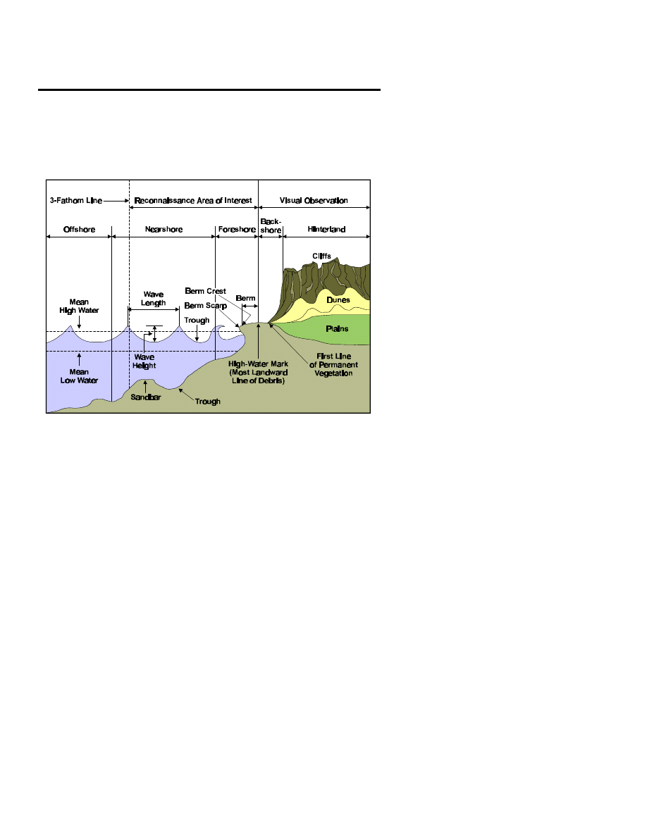
Beach Composition. This is a general description related
to the beach as a whole that is divided into two areas: the
foreshore (from MLW to mean high water (MHW)) and
the backshore (MHW to BOB). An assessment of under-
water composition is provided, as required. The following
letter codes should be used:
Beach Composition
Letter Code
Mud
A
Clay
B
Sand (up to pinhead size)
C
Gravel/shingle (up to top-of-thumb size)
D
Pebbles (up to clenched fist size)
E
Cobbles (up to human head size)
F
Boulders (larger than human head size)
G
Coral
H
Other (describe briefly in this line)
J
If there is a marked variation in composition along the
beach, this is to be reported, using code, by reference to
designated sounding line numbers; for example, HOTEL
1.A08 to B02 E means that the foreshore from sounding
line A08 to sounding line B02 is now composed of
pebbles.
MCRP 2-15.3B
Reconnaissance Reports
Guide

JULIET
Trafficability of the Beach. This is a general description
of the beach as a whole. Reports are provided on only
two areas: the foreshore (portion of the beach between
WLTS and MHW line) followed by the backshore (from
the MHW line to the line of first permanent vegetation or
BOB). This information will be reported by using these
letter codes:
Trafficability Conditions
Letter Code
Firm. Can be used by 2-wheel-
W
drive vehicles and 4-wheel-drive
vehicles with trailers unless heavy
and continuous use is intended.
Moderate. Can be used by military
X
3- to 5-ton vehicles, which should be
able to start from rest by using all-
wheel drive. Recommend that beach
matting/roadway be used.
Soft. Four-wheel-drive vehicles
Y
cannot start from rest but might
be able to cross a soft patch if
already on the move. It is
recommended that beach matting
or roadway be used.
Very Soft. This is impassable to
Z
42
CONBEREP
MCRP 2-15.3B
Reconnaissance Reports

wheeled vehicles. Tracked vehicles
may experience difficulty. Beach
matting/roadway is required.
Note: If there is a marked difference in trafficability along
the beach, this is to be reported in a similar manner to
line HOTEL above. Foreshore trafficability can only be
assessed above the WLTS. It must be clearly understood
that a correct assessment of trafficability cannot be guar-
anteed, bearing in mind the conditions under which the
team may be working. Allowances must be made for a
high degree of error. The only way to get an accurate as-
sessment of beach trafficability is to have the team return
with soil samples that are properly cataloged and
recorded.
KILO
Exits. This is a description of any new exits or exits that
have changed from the latest intelligence estimates. Each
beach exit is listed and described individually. The exits
are described by reporting the grid reference where the
exit meets the BOB, followed by a description using the
following letter codes:
Type of Beach Exit
Letter Code
Infantry. If the exit is usable by
A
infantry only, then the width of the
exit is reported following the letter
code.
Tracked Vehicles. If the exit is
B
MCRP 2-15.3B
Reconnaissance Reports
Guide

usable by both infantry and tracked
vehicles, then the width is reported
followed by the appropriate trafficability
code used in line JULIET of this report
and the width of the exit.
Wheeled Vehicles. If the exit is
C
usable by infantry and wheeled vehicles,
then the information is reported in the
same sequence as for tracked vehicles in
this line.
Unusable. This denotes exits that were
D
thought to be usable before the
insertion of the team and a proper
reconnaissance that determined such
information to be incorrect.
LIMA
Position of the Beach Reconnaissance Patrols. The po-
sition of an amphibious reconnaissance team (ART) after
completing its reconnaissance is given as a six-digit refer-
ence or by some other previously arranged system of ref-
erence. This information needs to be transmitted only if
the ART will be staying in the vicinity of the beach while
the assault is taking place or in some other way may af-
fect the scheme of maneuver or fire support plan of the
unit being supported.
MIKE
Enemy. If the enemy has been observed or contacted, this
information is reported sequentially by using the follow-
ing format:
44
CONBEREP
MCRP 2-15.3B
Reconnaissance Reports

1st. Grid reference of the enemy position/contact.
2nd. Strength/number of the enemy observed.
3rd. Weapons, especially any weapons or weapons
systems that could jeopardize the accomplishment of
the amphibious operation.
Note: A SPOTREP/SALUTE report should normally be
transmitted separately to clarify and more accurately de-
scribe all enemy sightings and possible intentions.
NOVEMBER
Remarks. Any additional information relevant to this re-
port can be included here. Any essential elements of in-
formation (EEIs) or other information requirements
(OIRs) should be stated in the patrol’s operation order
(OPORD) and will come down from CATF and com-
mander, landing force (CLF).
Notes:
1. The term right or left always refers to the beach area as viewed from
seaward, as if the reader of the report were a coxswain in a boat coming
into the beach.
2. One knot equals approximately 31 meters or 100 feet per minute of
movement. If the recorder were to toss an object into the water and meas-
ure how far it has moved in that current in one minute, he should be able
to approximate the speed and the direction of that current.
MCRP 2-15.3B
Reconnaissance Reports
Guide
3. If no change is found in the information already known, the relevant
line or subparagraph of that line is transmitted with that line heading fol-
lowed by NC (no change).
46
CONBEREP
MCRP 2-15.3B
Reconnaissance Reports

CONBEREP Worksheet
_______________ this is _______________
(receiver)
(sender)
CONBEREP -
(serial number followed by code name and map sheet details
as required)
ALPHA -
BRAVO -
CHARLIE -
DELTA - DP A -
DP B -
DP C -
ECHO -
FOXTROT - (F1)
MCRP 2-15.3B
Reconnaissance Reports
Guide

(F2)
(F3)
(F4)
(F5)
(F6)
(F7)
(F8)
(F9)
(F10)
GOLF -
HOTEL - (H1)
(H2)
(H3)
JULIET - (J1)
(J2)
KILO -
48
CONBEREP
MCRP 2-15.3B
Reconnaissance Reports

LIMA -
MIKE -
NOVEMBER (remarks) -
DTG -
MCRP 2-15.3B
Reconnaissance Reports
Guide

Contact Report (CONTACREP)
The CONTACREP, although not a standard report, is very useful for
briefly and concisely reporting any enemy contact. It consolidates the most
important IRs of the SITREP and the CASREP without wasting large
amounts of transmission time in a rapidly evolving and tenuous situation.
In such situations, the reconnaissance patrol leader must be able to con-
centrate all of his attention on resolving his patrol’s present situation and
continuing the mission, working out a plan to extract his patrol to a secure
area, or effecting the evasion and escape (E&E) plan.
C—Call sign. “(Receiver’s call sign) this is (originator’s call sign).”
O—Occurrence. Describes the type of contact/what has happened.
N—Needs. States medical evacuation, emergency extraction, immedi-
ate suppression, reinforcement, resupply, and other needs.
T—Time/Location. Indicates at what time the contact took place and
where. These coordinates do not need to be encrypted/shackled.
A—Actions Taken. Describes what the patrol has done since the con-
tact was made, for example, broken contact, E&E, or so on.
C—Casualties. Reports friendly KIAs/WIAs and transmits kill num-
bers from the warning order/kill sheet to assist the medical evacuation
when needed.
Note: The person transmitting the CONTACREP must be prepared to
authenticate if operating over an uncovered net. This is especially the
MCRP 2-15.3B
Reconnaissance Reports
Guide

case if the patrol is requesting emergency extraction, immediate suppres-
sion, medical evacuation, or reinforcement.
52
CONTACREP
MCRP 2-15.3B
Reconnaissance Reports Guide

CONTACREP Worksheet
Contact — Contact — Contact
___________
this is
____________
(receiver)
(sender)
Occurrence -
Needs -
Time/location -
Action taken -
MCRP 2-15.3B
Reconnaissance Reports
Guide

Casualties -
Remarks -
DTG -
54
CONTACREP
MCRP 2-15.3B
Reconnaissance Reports Guide

River/Estuary Report (DELTAREP)
Begin the report with the subject line of the message and the serial number
or code name, followed by map sheet details as required.
ALPHA
Units of Measurement. See the table on page 3.
BRAVO
Location. This line provides grid references of the begin-
ning and end of the section of the river/estuary actually
reconnoitered by the team.
CHARLIE
Main Channel. This information is reported in the fol-
lowing numbered sequence:
1. Location. The grid reference of the entrance to the
main channel is provided.
2. Seaward Approach. The bearing from seaward of
the approaches to the main channel (using the angular
unit of measurement designated in line ALPHA) is pro-
vided. If this information is already known and has not
changed, report NC. If this information does not apply to
this mission, then report NIL. If the team was unable to
determine this information because of the enemy situation
or other considerations, they will report NAR (not able to
record) and explain the reason in line KILO (remarks) of
this report.
3. Reference Points. The entrance to the main channel
may be fixed by means of transits and/or bearings of
prominent features that can be observed from seaward.
MCRP 2-15.3B
Reconnaissance Reports
Guide

These features must also be recognizable on a map or
chart (these reference points may be precoordinated and
assigned code names or other designations before the
team is inserted). This information is reported in the fol-
lowing sequence.
A. Prominent Features. This includes the descrip-
tion and location of the feature followed by its bear-
ing from seaward at the entrance to the main channel.
If more than one feature is being used to get a resec-
tion for the channel entrance, then the features are
numbered sequentially and described individually.
They are numbered 1, 2, 3, and so on.
- or -
B. Transits. Transits are two points that are recog-
nizable when viewed from seaward and can be lo-
cated on a map/chart. Transits will line up one behind
the other when the boat is on the correct azimuth to
the entrance to the main channel. Transits are re-
ported by giving a brief description of each point and
its location so that it can be plotted on a map/chart. If
more than one set of transits will be used to locate the
channel entrance, they will be reported individually
and numbered sequentially 1, 2, 3, and so on.
DELTA
Navigation Aids. A local system of buoys (if any) or
markers placed by the teams is reported by using the
following code:
Type of Navigation Aid
Number Code
56
DELTAREP
MCRP 2-15.3B
Reconnaissance Reports Guide

Starboard hand buoys (shape and
1
color)
Port hand buoys (shape and color)
2
Team-placed buoys/markers
3
(description and location)
ECHO
Hazards. These are reported in numbered sequence fol-
lowed by the letter code describing the type of hazard
then by the grid reference location of the hazard(s). The
following letter codes are used to describe the type of
hazard being reported:
Type of Hazard
Letter Code
Sandbars
A
Wrecks
B
Rocks
C
Tidal races
D
Nets
(describe)
E
Bridges
(report overhead clearance) F
Other
(describe as required)
G
FOXTROT
Navigational Limits. This line provides the highest point
upstream in the main channel with the following depth at
low water; this is a six- or eight-digit reference followed
by the following letter codes:
Navigational Limits
Letter Code
MCRP 2-15.3B
Reconnaissance Reports
Guide

2 meters
A
1 meter
B
1/2 meter
C
GOLF
Beaching/Landing Points and Exits. This information is
reported sequentially and in the following format:
1st.
Grid reference of the beaching/landing point.
2nd. Type of landing craft that can use the landing
point, indicated by the following letter code:
Type of Landing Craft
Letter Code
Landing craft, medium/utility
A
Landing craft, personnel
B
Shallow boats with outboard engines
C
Other craft as required
D
3rd. Overall trafficability of the beaching point and
exit, reported by using the following number code:
Trafficability
Number Code
Firm. Can be used by
1
2-wheel-drive vehicles
or 4-wheel-drive vehicles
with trailers unless heavy,
continuous use is intended.
Moderate. Can be used by
2
58
DELTAREP
MCRP 2-15.3B
Reconnaissance Reports Guide

3- or 5-ton vehicles, which
should be able to start from
rest by using all-wheel drive.
Recommend using beach
matting/roadway.
Soft. Four-wheel-drive vehicles 3
cannot start from rest but
might be able to cross a soft
patch if already on the move.
Recommend using beach
matting/roadway.
Very Soft. Impassable to
4
wheeled vehicles; tracked
vehicles may experience
difficulty. Use of beach
matting/roadway is required.
Notes:
1. If the landing point or its exits are unsuitable for
any vehicles, the letter code NIL is reported.
2. If the team confirms that information on sus-
pected beaching/landing points is correct, the team
will report NC.
4th. Width of exit, reported in the unit of measure-
ment designated in line ALPHA.
MCRP 2-15.3B
Reconnaissance Reports
Guide

HOTEL
Current. The speed of the current/tidal stream should be
indicated in the unit of measurement designated in line
ALPHA. The information is reported in the following
sequence:
1st. Velocity of the water.
2nd. Direction in which the current is flowing (use
the letter that would indicate the cardinal direction of
the water flow at the time of sounding (e.g., N
(north), NE (northeast), SW (southwest), etc.).
3rd. DTG and location (grid reference) of the
sounding.
Note: Several of these soundings may be required at
different locations in the waterway to more accu-
rately represent the current as the water flows toward
its mouth. Also, several soundings may be required at
the entrance to the waterway if tidal conditions are
present.
JULIET
Texture of the River Bed. This information is reported
in the following sequence:
1st.
Grid reference of where the bottom sample was
taken.
2nd. Letter code indicating the composition of the
river bottom:
River Bottom Composition
Letter Code
60
DELTAREP
MCRP 2-15.3B
Reconnaissance Reports Guide

Mud
A
Sand
B
Rock
C
Shingles
D
Vegetation
E
Other
(briefly describe)
F
KILO
Remarks. This line provides any other information that
has not been covered in the report and that could have an
impact on the riverine operation to be conducted. This
type of information should be covered in the IRs.
Note: If the patrol is to be extracted before the start of the
operation, they should bring back soil samples of the dif-
ferent key portions of the area that the team reconnoi-
tered. These need to be properly labeled and recorded. In
this manner, the unit being supported can more accurately
estimate the type of conditions under which it will be
operating.
MCRP 2-15.3B
Reconnaissance Reports
Guide

DELTAREP Worksheet
_______________
this is
_______________
(receiver)
(sender)
DELTAREP -
(serial number followed by code name and map sheet de-
tails as required)
ALPHA -
BRAVO -
CHARLIE - (C1)
(C2)
(C3)
DELTA -
ECHO -
FOXTROT -
ALPHA
BRAVO
CHARLIE
GOLF -
HOTEL -
62
DELTAREP
MCRP 2-15.3B
Reconnaissance Reports Guide

JULIET -
KILO (remarks) -
DTG -
MCRP 2-15.3B
Reconnaissance Reports
Guide

Drop Zone Report (DZREP)
Begin the report with the subject line of the message, the serial number,
and/or the drop zone code name or code identification letter (determined
and coordinated before the team is inserted), followed by map sheet details
as required.
ALPHA
Units of Measurement. See the table on page 3.
BRAVO
Time. This line provides the DTG that the reconnais-
sance was completed.
CHARLIE
Grid Reference of Point of Impact. The position of the
intended point of impact is reported by grid reference.
The point of impact is the selected point at which it is in-
tended for the first parachute from the drop run to make
impact with the ground.
DELTA
Height. The height AMSL of the point of impact and the
height AMSL of the highest point of the drop zone are re-
ported (in that sequence) by using the unit of measure-
ment designated in line ALPHA.
ECHO
Extremities of the Drop Zone. Grid references of the ex-
tremities of the drop zone are provided.
FOXTROT
Description. The drop zone is described in the following
sequence by using the units of measurement designated in
line ALPHA.
MCRP 2-15.3B
Reconnaissance Reports
Guide

1st.
Usable length.
2nd. Usable width.
3rd. Drop zone gradient.
Notes:
1. The gradient of the ground is expressed as a ratio.
2. Slope within the drop zone should preferably be less
than 1:10 and without surface irregularities.
3. Slopes steeper than 1:3 are unusable.
GOLF
Surface. A description of the surface of the drop zone
should be given in two parts by using the following codes:
1st
Surface Hardness of the
Number Code
Drop Zone
Hard. Can be used by 2-
1
wheel-drive vehicles
or 4-wheel-drive vehicles
with trailers unless heavy
and continuous use is intended.
Moderate. Can be used by 3-
2
and 4-ton vehicles, which should
be able to start from rest by using
66
DZREP

all-wheel drive.
Soft. Four-wheel-drive vehicles 3
cannot start from rest but might
cross if already on the move.
2nd
Nature of the Ground
in the Drop Zone
Letter Code
Sand
A
Grass
B
Scrub
C
Snow
D
Ice
E
Marsh
F
Other (describe briefly)
G
HOTEL
Drop Zone Obstructions. This information is reported in
the following sequence by using the following code:
1st.
Bearing of obstacle from the point of impact.
2nd. Type of obstacle, using the following letter
code.
3rd. Distance of the obstacle from the point of
impact.
MCRP 2-15.3B
Reconnaissance Reports
Guide

Note: Use the units of measurement recorded in line AL-
PHA of this report.
Type of Obstruction
Letter Code
Rocks
A
Buildings
B
Fences
C
Hedges
D
Trees
E
Poles
F
Pylons/high-tension wires
G
Water obstacles (be specific)
H
Ditches
J
Craters
K
Other (specify in this line)
L
JULIET
Suitability and Type of Drop Zone. This line indicates,
by the following numerical code, whether the drop zone is
suitable for the following:
Type of Drop
Number Code
Personnel drop
1
Platform drop
2
Supply drop
3
Other (specify)
4
68
DZREP

Notes:
1. Characteristics of Personnel Drop Zones:
A. Surface. A flat, resilient surface without obstruc-
tions is technically the most suitable for a troop drop
zone.
B. Obstacles. Obstacles preventing the use of a
drop zone are built-up areas; high-tension wires;
cliffs; ravines; and normally rivers, ponds, and lakes
near the intended drop zone. However, jumps on
lakes or in any large body of water can be carried out
by specially equipped and trained personnel.
C. Other Areas. If considered operationally neces-
sary, drops may be made in wooded or forested areas,
mountains, or lakes by using specially equipped and
trained personnel.
2. Special Considerations for a Cargo Drop Zone.
The required characteristics are similar to those for per-
sonnel drop zones. In addition, they should be accessible
to vehicles or at least crossed by paths to simplify the col-
lection of the equipment and supplies. Dropping supplies
over water should be considered only under special
circumstances.
3. Special Drop Methods. Use of methods such as
ultra-low-level-approach (ULLA) will require specialist
MCRP 2-15.3B
Reconnaissance Reports
Guide

representation on the team or at least special training in
the technique to be employed.
KILO
Vehicle Exit Points. This line reports, by grid reference,
possible vehicle exit points from the drop zone to prede-
termined line(s) of communications.
LIMA
Drop Zone Markings. All drop zone marking/location
aids are to be prebriefed, and only variations from the
brief need to be reported. When smoke is being used as a
drop zone location aid, the team should indicate when
smoke is being released but not the color. The pilot of the
lead aircraft should read back the color seen, and the
team should confirm that the correct color has been spot-
ted. A no drop signal should also be prebriefed before the
team is inserted.
MIKE
Recommended Direction of Run In/Run Out Tracks.
This line reports recommended tracks for the aircraft run
in/run out; these are expressed in the unit of measurement
listed in line ALPHA. This information is transmitted in
the following sequence:
1st.
Primary run in/primary run out track.
2nd. Alternate run in/alternate run out track.
NOVEMBER
Target Approach Point (TAP). The recommended TAP
should be reported only if one is observed that is
70
DZREP

more suitable than that previously selected and briefed. If
applicable, report in the following sequence:
1st.
Primary TAP.
2nd. Alternate TAP.
PAPA
Obstacles and Hazards on the Run In/Run Out
Tracks. This line reports major obstacles in the vicinity
of the drop zone and along recommended run in/run out
tracks. If unable to recommend run in/run out tracks, all
major obstacles and hazards in the area are reported by
using the following letter codes and sequence:
Type of Obstacles/Hazards
Letter Code
High-tension wires
A
Built-up areas
B
Cliffs
C
Ravines
D
Water obstacles (specify what type) E
Wooded areas
F
Masts, chimneys, or pylons (specify)
G
High ground
H
Other (describe briefly)
J
MCRP 2-15.3B
Reconnaissance Reports
Guide

The following is the sequence that will be used to report
this information:
1st.
Bearing from the impact point (IP).
2nd. Type of obstacle (using the letter code).
3rd. Distance from IP.
4th. Height of obstacle (using unit of measurement
designated in line ALPHA).
Note: If it has not been possible to fully observe the area
between the TAP and the drop zone, the suffix N (not ob-
served) should be added to the end of this line.
QUEBEC
Ground-Air Communications. This line includes pri-
mary and alternate ground-air communications line num-
bers if they are different from the precoordinated
frequencies. The changes will be reported in the following
order:
1st.
Primary frequency.
2nd. Alternate frequency.
ROMEO
Enemy. Known enemy positions, strengths, and weapons
are to be reported sequentially in the following format:
1st.
Grid reference of the enemy position.
72
DZREP

2nd. Strength/number of enemy observed.
3rd. Weapons, especially any weapons systems that
could jeopardize the accomplishment of the airborne
operation.
Note: A SPOTREP/SALUTE report should normally be
transmitted to clarify and more accurately describe all en-
emy sightings and intentions.
SIERRA
Weather. The weather is reported at the time that the re-
connaissance is completed and as required and briefed be-
fore the team is inserted. This information will be
reported in the following sequence:
1st. Wind direction (from which the wind is blowing)
and estimated speed (using units of measurement des-
ignated in line ALPHA of the report).
2nd. Cloud cover—the portion of the sky that is ob-
scured, in eighths, and the estimated base above the
drop zone.
3rd. Visibility.
4th. Temperature.
TANGO
Remarks. Other information that is not covered as part
of the report but that could prove vital to the accom-
plishment of the supported unit’s scheme of maneuver is
MCRP 2-15.3B
Reconnaissance Reports
Guide

included. This information should be covered as part of
the patrol’s IRs.
Notes:
1. Lines from the report need not be transmitted when
the information is either already known or not required.
NC (no change) can be used to confirm information al-
ready prebriefed in the reconnaissance brief.
2. The following documents are relevant to determining
the precise parameters for size and marking of the zone.
A. Standardization Agreement (STANAG) 3570,
Drop Zones and Extraction Zones
—
Criteria and
Marking.
B. The appropriate national standing orders, manu-
als, or instructions on drop zones.
74
DZREP

DZREP Worksheet
_______________
this is
_______________
(receiver)
(sender)
DZREP -
(serial number followed by code name and map sheet details as
required)
ALPHA -
BRAVO -
CHARLIE -
DELTA -
ECHO -
FOXTROT - (F1)
(F2)
(F3)
GOLF -
HOTEL -
JULIET -
MCRP 2-15.3B
Reconnaissance Reports
Guide

KILO -
LIMA -
MIKE - (M1)
(M2)
NOVEMBER - (N1)
(N2)
PAPA -
QUEBEC -
ROMEO -
SIERRA - (S1)
(S2)
(S3)
(S4)
TANGO (remarks) -
DTG -
76
DZREP

Flash/Action Report (FLASHREP) and Worksheet
Flash - Flash - Flash _______________ this is ____________
(receiver)
(sender)
1. *Type of report: flash report/action report (state applicable report) -
(serial number followed by code name and map sheet details as
required)
2. *Reporting unit -
3. *Time:
A. DTG of report -
B. DTG of incident -
4. Reference -
5. *Location:
A. Enemy -
B. Friendly (encrypted) -
6.
*Incident description -
MCRP 2-15.3B
Reconnaissance Reports
Guide

7. *Action taken/being taken by the unit initiating the report -
8. Friendly casualties (encrypted):
A. KIA -
B. WIA-
C. MIA-
9. Enemy casualties:
A. KIA -
B. KIA probable -
C. Prisoners of war (POWs) -
D. Suspects -
E. Other indigenous captives -
10. Captured enemy weapons, equipment, and documents -
78
FLASHREP
MCRP 2-15.3B
Reconnaissance Reports

11. Friendly weapons/equipment damaged, destroyed, or lost -
12. Remarks -
DTG -
*Indicates minimum report requirements for a FLASHREP.
MCRP 2-15.3B
Reconnaissance Reports
Guide

Frequency Interference Report (FIRREP) and Worksheet
All incidents will be reported via secure means as soon as possible.
_______________ this is _______________
(receiver)
(sender)
FIRREP -
(serial number followed by code name and map sheet details as
required)
1. Time -
2. Unit -
3. Frequency -
4. Type (meaconing/intrusion/jamming/interference) -
5. Remarks -
DTG -
MCRP 2-15.3B
Reconnaissance Reports Guide
81

River Ford Report (FORDREP)
Begin the report with the subject line followed by the serial number and
map sheet details as required.
ALPHA
Units of Measurement. See the table on page 3.
BRAVO
DTG. This line reports the DTG of when the ford recon-
naissance was completed.
CHARLIE
Location. This line provides the grid reference of the
fording site followed by engineer classification, if known.
DELTA
Capabilities. The type of traffic that the ford is capable
of supporting is reported by using the following numeri-
cal code:
Type of Traffic
Number Code
Light infantry
1
Light military vehicles
2
(no snorkeling gear)
Light military vehicles
3
(with snorkeling gear)
Swimming vehicles
4
Other
5
ECHO
Length of Ford. A measurement of the distance from en-
trance point to exit point is reported in the unit of meas-
urement designated in line ALPHA.
MCRP 2-15.3B
Reconnaissance Reports
Guide

FOXTROT
Depth and Velocity of Running Water. These are re-
ported in the unit of measurement designated in line AL-
PHA. This information will be recorded and transmitted
in the following sequence:
1st. Depth of the water at the ford site.
2nd. Velocity of the water at the ford site.
3rd. DTG of the sounding.
Climatic, tidal, or other considerations may dictate that
several soundings are required for the supported unit to
determine the suitability of the ford site to support their
scheme of maneuver. If more than one sounding is re-
quired, then the soundings will be reported sequentially
and individually.
Example:
F1.3/2 042315H
F2.6/7 050340H
GOLF
Ford Bottom Composition. This information is reported
by using the following numerical code:
Bottom Composition
Number Code
Mud
1
Clay
2
Sand
3
Rock
4
Gravel
5
Artificial pavement
6
84
FORDREP

Other (followed by description)
7
HOTEL
Gradient of the Ford’s Approach and Exit. This infor-
mation is reported, using a ratio to represent the percent-
age of slope, in the following sequence: the slope of the
ford approach followed by the percentage of slope for the
ford exit.
JULIET
Composition of the Ford’s Approach and Exit. This in-
formation is reported by using the same number code
used in line GOLF and in the same sequence as in line
HOTEL.
Example: J1.5
J2.4
In this example, the ford approach is composed of gravel,
and the ford exit is composed of rock.
KILO
Usable Width of Approach and Exit. This information
is reported in the same sequence as lines HOTEL and JU-
LIET, using the unit of measurement designated in line
ALPHA.
LIMA
Remarks. Any other information is reported that could be
vital to the scheme of maneuver of the unit that the ART
is supporting and should be designated in the patrol’s
IRs.
MCRP 2-15.3B
Reconnaissance Reports
Guide

River FORDREP Worksheet
__________________
this is
_________________
(receiver)
(sender)
FORDREP -
(serial number followed by code name and map sheet
details as required)
ALPHA -
BRAVO -
CHARLIE -
DELTA -
ECHO -
FOXTROT -
GOLF -
HOTEL - (H1)
(H2)
JULIET - (J1)
(J2)
KILO - (K1)
86
FORDREP

(K2)
LIMA (remarks) -
DTG -
MCRP 2-15.3B
Reconnaissance Reports
Guide

Helicopter Landing Site Report (HELLSREP)
Begin the report with the subject line and the serial number, followed by
the helicopter landing site designation (coordinated before the insertion of
the team) and map sheet details as required.
ALPHA
Units of Measurement. See the table on page 3.
BRAVO
DTG. This line provides the DTG of when the heli-
copter landing zone reconnaissance was completed.
CHARLIE
Location. Location is reported as grid references (or
by another precoordinated method of position location)
of the extremities of the landing site. It is prefixed by
the two-letter grid zone designator when there is any
possibility of uncertainty about the map sheet(s) on
which the team is reporting.
DELTA
Orientation of the Long Axis of the Landing Site.
This is reported by using the unit of measurement des-
ignated in line ALPHA of the report.
ECHO
Number and Size of the Landing Points. Sizes of the
landing points are reported as L (large), M (medium),
or S (small), as briefed in STANAG 3570. This infor-
mation should be reported in the following sequence:
1st. The number of each size of landing points.
2nd. The code for the type of landing points being
reported.
MCRP 2-15.3B
Reconnaissance Reports
Guide

FOXTROT
Method of Deplaning. The following numerical code is
used to determine the safest and most tactically sound
method of deplaning.
Method of Deplaning
Number Code
Land
1
Hover
2
Fastrope
3
Rappel
4
Special patrol insertion and extraction
5
(SPIE)
Other (specify in this line)
6
Note: The method of deplaning is determined by the na-
ture of the ground and vegetation at the insertion point.
For helicopters to land, the landing point must be
cleared of all obstructions that are liable to damage the
wheels/skids, underbelly, or aerials of the helicopter.
The ground must not have a slope with a ratio greater
than 1:8, unless otherwise briefed. Maximum heights of
other methods of deplaning are:
Method of Deplaning
Maximum Height
Hover
6 feet
Rappel
90 feet
Fastrope
120 feet
Abseil/winch
200 feet
Rope climb
30 feet
90
HELLSREP
MCRP 2-15.3B
Reconnaissance Reports

GOLF
Landing Site Surface. The information in this line is
reported in three parts by using the following sequence
and letter/numerical codes:
1st.
Trafficability of the landing site:
Trafficability of
Number Code
the Landing Site
Hard. The surface can
1
support the helicopter and be
used by 2-wheel-drive vehicles
or 4-wheel-drive vehicles with
trailers unless heavy and
continuous use is intended.
Moderate. The surface can
2
support the helicopter and be
used by 3- or 5-ton vehicles,
which should be able to start
from rest when using all-
wheel drive.
Soft. The helicopter can land, 3
but if the surface is wet it could
cause suction to form on the
wheels/skids of the helicopter.
Four-wheel-drive vehicles cannot
start from rest but should be
able to cross the landing site if
MCRP 2-15.3B
Reconnaissance Reports
Guide

already on the move.
2nd.
Type of landing surface:
Type of Landing Surface
Letter Code
Sand
A
Grass
B
Scrub
C
Snow
D
Ice
E
Marsh
F
Dust
G
Paddy
H
Other (specify and describe)
J
Note: When the ground is covered with snow, also
report the subsurface of the landing site.
3rd. Ability of the surface of the landing site to re-
circulate. Whether or not the surface will recircu-
late is reported by marking Y (yes) or N (no).
Recirculation is the effect of the downwash from
the helicopter, which is liable to pick up sand, dust,
or snow and blow it through the rotors, thereby se-
verely reducing visibility for the pilot. This will
have an effect on the frequency at which the heli-
copters can safely land and take off.
HOTEL
1. Direction of Approach
92
HELLSREP
MCRP 2-15.3B
Reconnaissance Reports

2. Direction of Egress
Notes:
1. The approach and egress azimuths are reported in
the unit of measurement designated in line ALPHA.
Whenever possible, these directions are into the wind.
Oftentimes, the enemy situation, orientation of the long
axis of the landing site, and obstacles surrounding the
landing site will dictate an alternate direction.
2. Direction of approach is not necessarily the same
as the direction of landing, which will normally be de-
cided by the pilots.
JULIET
Wind Direction and Speed. Wind direction is re-
ported as the direction from which the wind is coming;
this is the same bearing that a helicopter would use to
fly into the wind. These measurements are reported by
using the units of measurement designated in line
ALPHA.
KILO
Approach Angle. This is dictated by the height and
proximity of surrounding obstacles. The normal maxi-
mum angle should be no steeper than 1:10. Other limits
may be prebriefed depending on the squadron’s stand-
ing operating procedures and other considerations, such
as height AMSL and weight restrictions on the
helicopters.
MCRP 2-15.3B
Reconnaissance Reports
Guide

LIMA
Locations and Types of Recognition Aids. The loca-
tions and types of landing site recognition aids that are
provided for any particular team must be prebriefed
and coordinated with the aviation combat element and
the ground combat element before the insertion. The
recognition signals must be assigned letter codes simi-
lar to those listed below. These should be changed and
updated before each operation as the situation dictates.
The information in this line is reported in the following
sequence by using letter codes that are coordinated be-
fore the operation and insertion.
1st. Grid reference of the recognition aids.
2nd. Type of recognition aid employed of those
precoordinated, for example:
Type of Recognition Aid
Letter Code
Green smoke
A
Yellow air panel
B
Signal mirror
C
Strobe light
D
Other (specify)
E
MIKE
Landing Aids. Landing aids that are provided for the
team must be coordinated, before the team is inserted,
in the same manner that recognition signals must be
preplanned. These must be changed and updated before
each operation as the situation dictates. If no landing
aids are to be used, report NIL.
94
HELLSREP
MCRP 2-15.3B
Reconnaissance Reports

Type of Landing Aid
Number Code
Glide slope indicator
1
Torch “T”
2
Inverted “Y”
3
Other (specify)
4
NOVEMBER
Cloud Cover and Estimated Height Above the
Landing Site. This is reported in the following
sequence:
1st. The percentage of the sky that is obscured by
clouds. This information is reported in eighths
(e.g., half cloud cover would be reported as 4;
small patches would be reported as 1).
2nd. Estimated height of clouds above the landing
site. This is reported as the lowest cloud above the
landing site. This height is estimated and reported
in the unit of measurement designated in line
ALPHA.
PAPA
Visibility and Temperature. This information is re-
ported in the following sequence by using the units of
measurement designated in line ALPHA.
1st. Visibility on the landing site.
2nd. Temperature on the landing site.
MCRP 2-15.3B
Reconnaissance Reports
Guide

QUEBEC
Enemy. Known enemy positions, strength, and weap-
ons are to be reported as a sighting number followed by
grid reference, strength, and weapons critical to the ac-
complishment of the helicopterborne operation.
Note: A SPOTREP/SALUTE report should be trans-
mitted for each enemy sighting to further clarify all en-
emy sightings and to give higher headquarters a better
idea of the enemy’s strength and possible intentions.
ROMEO
Position of the ART. This line is transmitted only if
the team is staying in proximity to the landing zone
during the helicopterborne operation. This information
is reported to prevent the team from being mistaken for
the enemy.
SIERRA
Obstructions. Obstructions in the direction of the heli-
copter’s approach and exit are to be reported by using
the following letter code:
Type of Obstruction
Letter Code
Building
A
Trees
B
Poles
C
Pylons and high-tension wires
D
Other (specify and describe in this line)
E
Note: Obstacles will be reported sequentially by using
the following format:
1st. Grid reference of the obstacle.
96
HELLSREP
MCRP 2-15.3B
Reconnaissance Reports

2nd. Code letter of the obstacle.
3rd. Height of the obstacle (using the unit of meas-
urement designated in line ALPHA).
TANGO
Exits From the Landing Site. This line is used to de-
scribe all exit points from the landing site. Exits are re-
ported in the following sequence:
1st. Grid reference of the landing site exit.
2nd. Description of the exit using the following let-
ter code:
Exit Description/Capabilities
Letter Code
Infantry. If the exit is usable by
A
infantry only, report the exit
width after the letter code (using
the unit of measurement designated
in line ALPHA) and describe the
type of exit.
Wheeled Vehicles. If the landing
B
site exit is usable by both infantry
and wheeled vehicles, report
the exit description by using the
letter designator followed by
the width of the exit.
MCRP 2-15.3B
Reconnaissance Reports
Guide

Unusable. This letter code will
C
report that the team was unable
to locate any adequate exits from
the landing site.
UNIFORM
Restrictions to Troop Movement. Report the degree
of restriction of rapid troop deployment from the land-
ing site. This information is reported by using the fol-
lowing numerical code:
Degree of Troop Movement
Number
Restrictions
Code
Heavy restrictions to movement
1
Moderate restrictions to movement
2
Unrestricted movement
3
VICTOR
Remarks. Other pertinent information, such as a land-
mark to the landing zone, can be described in this para-
graph, along with any other information as designated
in the patrol’s IRs.
Notes:
1. Any line from the report for which the information is
not known or not required should not be transmitted (to
prevent the team from being located). NC (no change)
is transmitted to confirm information given in the re-
connaissance briefing.
98
HELLSREP
MCRP 2-15.3B
Reconnaissance Reports

2. Helicopters can easily be deceived by the enemy un-
less precoordinated recognition signals are used by the
team manning the landing site.
3. When smoke is being used as a location aid for the
helicopters, the team should indicate when the smoke is
being released but not the color. The pilot of the lead
helicopter should verify the color of the smoke seen,
and the team will confirm that it is indeed the correct
signal. Also, teams should avoid using white phospho-
rous (WP)/white smoke (HC) in areas where there is
much smoke from fires, as this will confuse the pilots
and waste valuable time.
4. A wave-off signal should be precoordinated before
the team is inserted in case the landing site is compro-
mised immediately before the helicopters land.
5. When the team and the helicopters are transmitting
on an uncovered net, the team must be prepared to
authenticate when transmitting the zone brief before the
helicopters come into the zone.
MCRP 2-15.3B
Reconnaissance Reports
Guide

HELLSREP Worksheet
_______________
this is
_______________
(receiver) (sender)
HELLSREP -
(serial number followed by designation and map sheet
details as required)
ALPHA -
BRAVO -
CHARLIE -
DELTA -
ECHO -
FOXTROT -
GOLF -
HOTEL - (H1)
(H2)
JULIET -
KILO -
LIMA -
100
HELLSREP
MCRP 2-15.3B
Reconnaissance Reports

MIKE -
NOVEMBER - (N1)
(N2)
PAPA -
QUEBEC -
ROMEO -
SIERRA -
TANGO -
UNIFORM -
VICTOR (remarks) -
DTG -
MCRP 2-15.3B
Reconnaissance Reports
Guide

Meaconing, Intrusion, Jamming, and Interference
Report (MIJIREP) and Worksheet
______________
this is
_______________
(receiver)
(sender)
MIJIREP -
(serial number followed by code name and map sheet details
as required)
All incidents will be reported via secure means as soon as possible.
1. Type of report -
A. Meaconing. Transmission of false navigation signals.
B. Intrusion. Bogus stations, imitative deception.
C. Jamming. Deliberate disruption of friendly communications.
D. Interference. Natural or manmade obstructions that cause
difficulty in receiving radio signals.
2. Effects on station -
3. Station location -
4. Frequency or channel affected -
5. Type of equipment affected -
MCRP 2-15.3B
Reconnaissance Reports
Guide

6. Characteristics of interference -
7. Strength of interference -
8. Time that the interference started -
9. Effectiveness of interference (use a scale of 1-10) -
10. Operator’s name and rank -
11. Remarks (explain exactly what happened) -
Note: Lines 10 and 11 will be omitted if transmitted electronically.
DTG -
104
MIJIREP
MCRP 2-15.3B
Reconnaissance Reports

Nuclear, Biological, and Chemical Report (NBCREP)
Begin the report with the subject line, including map sheet details as
required.
ALPHA
Units of Measurement. See the table on page 3.
BRAVO
Location of Observer. This line describes the ob-
server’s position by using a grid reference (encrypted) or
some other precoordinated method of position location.
CHARLIE
Direction. This line indicates the direction of attack
from the observer by using the unit of measurement des-
ignated in line ALPHA.
DELTA
Time Attack Started. This line reports the DTG that
the attack started.
ECHO
Time Attack Ended. This line reports the DTG that the
attack ended.
FOXTROT
Location of Area Being Attacked. This information
should not be encrypted because the enemy already
knows the area that is being attacked.
GOLF
Type of Attack. The type of delivery system being used
is stated: mortars, artillery, rockets, missiles, spray, or so
on.
MCRP 2-15.3B
Reconnaissance Reports
Guide

HOTEL
Wind Direction and Velocity. The direction from which
the wind is blowing is reported by using the unit of meas-
urement designated in line ALPHA.
JULIET
Type of Agent. If it can be determined, the type of agent
is reported; if not, the observed effects are reported.
KILO
Remarks. This line includes remarks as stated in the pa-
trol’s IRs.
106
NBCREP

NBCREP Worksheet
_______________
this is
_______________
(receiver)
(sender)
NBCREP -
(serial number followed by code name and map sheet details
as required)
ALPHA -
BRAVO -
CHARLIE -
DELTA -
ECHO -
FOXTROT -
GOLF -
HOTEL -
JULIET -
KILO (remarks)-
DTG -
MCRP 2-15.3B
Reconnaissance Reports
Guide

Railroad Reconnaissance Report (RAILREP)
Begin the report with the subject line, the serial number followed by rail-
road designation (determined before the team is inserted), and map sheet
details as required.
ALPHA
Units of Measurement. See the table on page 3.
BRAVO
DTG. This line reports the DTG of when the reconnais-
sance was completed.
CHARLIE
Location and Direction. This line provides the location
of the beginning and end of that part of the railroad that is
actually reconnoitered. The cardinal direction of the axis
is indicated with letters, for example, N (north), E (east),
SW (southwest), and so on.
DELTA
Military Classification. This assessment will only be
made by qualified personnel.
ECHO
Length of Rails and Number of Ties. This information
is passed in two sections. The first section passes the
length of an individual section of rail, and the second sec-
tion passes the number of ties per rail section. The length
is reported using the unit of measurement reported in line
ALPHA. Line ECHO information is transmitted in the
following manner:
E1.10
E2.8
MCRP 2-15.3B
Reconnaissance Reports
Guide

In this example, ten represents the ten-meter length of
each rail section, and eight represents the number of ties
per rail section.
FOXTROT
Track Gauge. This is reported as directed in the team’s
OPORD IRs, which must be fully understood before
insertion.
GOLF
Track Width. This is reported in the following
sequence:
1st. Outside width of track.
2nd. Inside width of track.
3rd. Width of railroad bed.
HOTEL
Composition of Railroad Bed. A soil sample should be
brought back to be examined as part of the patrol report.
Bed composition is reported by using the following nu-
merical codes:
Railroad Bed Composition
Number Code
Rock
1
Gravel
2
Cinders
3
Timber
4
Concrete
5
Other (specify and briefly describe)
6
110
RAILREP
MCRP 2-15.3B
Reconnaissance Reports

JULIET
Gradient. This is reported as a ratio. Critical gradients
should be given in the team’s OPORD IRs.
KILO
Railroad Conditions. If any portion of the track is dam-
aged, the damage can be reported by using the following
numerical code:
Track Condition
Number Code
Undamaged
1
Boobytrapped But Not
2
Damaged. The track is undamaged,
but engineers will be required to
clear all boobytraps to make the
track safe so that it may be used by
friendly units.
Slightly Damaged. The track is damaged
3
but probably capable of safely allowing
trains to pass at a reduced rate of
speed and limited load capacity.
Engineering work is required to allow
the trains to travel at a sustained and
safe rate.
Significantly Damaged. The track is not
4
safe for passage of troops or cargo.
Tracks will require a major engineering
effort to make them safe for traffic but
will not require starting a new track at a
new location.
MCRP 2-15.3B
Reconnaissance Reports
Guide

Destroyed
5
Concealment. The availability of concealment from the
air should be reported by using the following code:
Concealment Along Tracks
Number Code
Good concealment is available at
1
regular intervals along the route.
Some concealment is available.
2
Little or no concealment is available.
3
MIKE
Track Constrictions. Railroad constrictions will be re-
ported in the following sequence:
1st. Nature of constriction.
2nd. Location of constriction.
3rd. Type of constriction, using the following letter
code and units of measurement designated in line
ALPHA:
Type of Constriction
Letter Code
Height
A
Width
B
Radius of a curve
C
Gradient
D
112
RAILREP
MCRP 2-15.3B
Reconnaissance Reports

Other (specify and describe)
E
NOVEMBER
Location of Switching Stations. This line provides grid
locations of all switching stations along the section of the
rail line that has been reconnoitered.
PAPA
Activity. All rail traffic along the route is reported, with
emphasis on military traffic. Each sighting is numbered
sequentially and includes the following information re-
ported in the following sequence:
1. DTG of sighting.
2. Speed of the enemy train, reported by using the unit
of measurement designated in line ALPHA followed by
the cardinal direction: N (north), SW (southwest), NE
(northeast), and so on.
3. Location of the sighting, reported by grid reference.
4. Composition of the train in the following sequence: the
number of each type of railroad car followed by the letter
code that designates that type of car.
Train Composition
Letter Code
Engines
A
Personnel
B
Freight
C
Flat car
D
Fuel car
E
MCRP 2-15.3B
Reconnaissance Reports
Guide

Train Composition
Letter Code
Chemical car (describe)
F
Cattle/livestock
G
Other (specify and describe)
H
QUEBEC
Remarks. Other information not listed in the report but
listed in the team’s OPORD IRs should be reported as it
applies to the mission in this line.
Notes:
1. Individual follow-up reports should be provided for all bridges and
other constrictions along the route.
2. Follow-up SPOTREPs/SALUTE reports should be provided for enemy
activity along the railroad line.
114
RAILREP
MCRP 2-15.3B
Reconnaissance Reports

RAILREP Worksheet
__________________
this is
____________________
(receiver)
(sender)
RAILREP -
(serial number followed by code name and map sheet details
as required)
ALPHA -
BRAVO -
CHARLIE -
DELTA -
ECHO - (E1)
(E2)
FOXTROT -
GOLF - (G1)
(G2)
(G3)
HOTEL -
MCRP 2-15.3B
Reconnaissance Reports
Guide

JULIET -
KILO -
LIMA -
MIKE -
NOVEMBER -
PAPA (remarks) -
DTG -
116
RAILREP
MCRP 2-15.3B
Reconnaissance Reports

Route and Road Report (ROUTEREP)
Begin the report with the subject line of the message followed by the serial
number and map sheet details as required.
ALPHA
Units of Measurement. See the table on page 3.
BRAVO
Location. This line provides a grid reference of the start
and finish of that part of the route that is actually
reconnoitered.
CHARLIE
Type of Route. The type of route is indicated by the fol-
lowing letter code:
Type of Route
Letter Code
All-weather route
X
Limited all-weather route
Y
Fair-weather route
Z
Notes:
1. Route type X has the following characteristics:
A. The route is passable to all traffic in any
weather, except in deep snow or during flooding.
B. The route normally includes roads with water-
proof surfaces only.
MCRP 2-15.3B
Reconnaissance Reports
Guide

2. Route type Y has the following characteristics:
A. Volume of traffic may be limited by bad weather,
for example, muddy verges or shoulders.
B. The route normally includes roads that do not
have waterproof surfaces and are considerably af-
fected by rain, frost, thaw, or heat.
C. Roads may have to be closed for short periods.
Heavy unrestricted use during adverse weather may
cause a complete breakdown of the route surface.
3. Route type Z has the following characteristics:
A. Passage is possible only during fair weather.
B. The route quickly becomes impassable in bad
weather.
C. The route cannot be kept open by maintenance
short of major construction.
DELTA
Military Classification. This assessment will be made
only by qualified personnel, for example, construction/
combat engineers:
Class 50. Average traffic routes.
Class 80. Heavy traffic routes.
Class 100. Very heavy traffic routes.
118
ROUTEREP

ECHO
Width. The width of the route is reported in two parts.
The first is the average width of the traveled way. The
second is the average width of the entire route, including
grading of the shoulder of the route. These measurements
are reported by using the units of measurement desig-
nated in line ALPHA. The traveled way is the hard sur-
face of the road/route; the width of grading is the width of
the traveled way plus the width of the hard shoulders of
the route.
FOXTROT
Route Constrictions. These are listed individually and
described in the following sequence:
1st. Nature of constriction. This information is re-
ported by using the following numerical code:
Type of Route Constriction
Number Code
Height constriction
1
Width constriction
2
Radius-of-a-curve constriction
3
Gradient constriction
4
Other
5
2nd. Location of the constriction.
3rd. Dimension of the constriction, using the unit of
measurement designated in line ALPHA.
4th. Bypass potential of the constriction, using the
following letter code:
MCRP 2-15.3B
Reconnaissance Reports
Guide

Bypass Potential
Letter Code
Bypass easy—local detour
P
possible without engineering
effort.
Bypass difficult—bypass possible
Q
only after engineering
improvements.
Bypass impossible.
R
Note: The critical heights, widths, radius of a curve, and
gradients will be reported by using the criteria set forth in
the IRs of the reconnaissance plan.
GOLF
Concealment. The availability of concealment from the
air will be categorized by using the following numerical
code:
Type of Concealment
Number Code
Good Concealment. Available
1
at regular intervals along the
reconnoitered section of the route.
Some Concealment. Available
2
along the reconnoitered part of
the route.
Little or No Concealment. Little
3
to no concealment available along
120
ROUTEREP

the route actually reconnoitered.
HOTEL
Special Considerations. This line of the report includes
any other factors that may have to be considered by any
landing force that intends to use the reconnoitered route.
The main meteorological obstacles are snow, flooding,
and ice. Other considerations could include such prob-
lems as refugees and local traffic. Hazards are listed by
using the following numerical codes:
Type of Hazard
Number Code
Snow (refer to notes below)
1
Flooding (refer to notes below)
2
Ice (refer to notes below)
3
Other (describe)
4
Note: The following letter codes are used as suffixes to
clarify the seriousness of the snow, flooding, or ice condi-
tion being reported.
Snow Conditions
Letter Code
There is no hindrance to wheeled
P
vehicles.
Movement is difficult for 4-
Q
wheel-drive vehicles. Some
digging or other route
preparation may be necessary
in places.
MCRP 2-15.3B
Reconnaissance Reports
Guide

Movement is impossible for wheeled
R
vehicles.
Note: The letter code describing the snow conditions is
followed by the depth of the snow, which is provided by
using the unit of measurement reported in line ALPHA.
Flooding Conditions
Letter Code
There is no hindrance to wheeled
P
vehicles.
Movement is difficult for wheeled
Q
vehicles. Some route preparation
may be necessary in some places.
Waterproofing or fording gear is
recommended by the team.
Movement is impossible for wheeled
R
vehicles.
Note: The letter code is followed by the depth of the
flooding over the roads/trails, using the unit of measure-
ment reported in line ALPHA.
Ice Conditions
Letter Code
There is no hindrance to wheeled
P
vehicles.
Movement is difficult for wheeled
Q
vehicles. Some salting or spreading
122
ROUTEREP

of gravel/sand in places is required to
make the route passable.
Movement is impossible for wheeled
R
vehicles without route preparation
before vehicle use of the route.
The condition is temporary; ice should
S
melt off. The letter code is followed
by the DTG of when the team expects
the ice to melt.
Note: The letter code describing the ice condition should
be followed by the depth of the ice on the route. If the
condition is temporary and the time/DTG when the ice
condition should clear can be estimated, then this estimate
is sent.
JULIET
Remarks. Any additional information that may be helpful
to operational planning and possible unit deployment, for
example, drifting conditions of snow, speed of water dur-
ing flooding conditions, wind speed and wind chill infor-
mation, and so on, is provided.
MCRP 2-15.3B
Reconnaissance Reports
Guide

ROUTEREP Worksheet
_______________
this is
______________
(receiver)
(sender)
ROUTEREP -
(serial number followed by code name and map sheet
details as required)
ALPHA -
BRAVO -
CHARLIE -
DELTA -
ECHO -
FOXTROT -
GOLF -
HOTEL -
JULIET (remarks) -
DTG -
124
ROUTEREP

Standard Shelling Report (SHELREP), Mortaring Report
(MORTREP), or Bombing Report (BOMREP) (State Which)
ALPHA
Units of Measurement. See the table on page 3.
BRAVO
Unit of Origin. This line reports the current call sign, ad-
dress, and group or code name.
CHARLIE
Position of Observer. A grid reference is preferred. This
should be encoded if the station is operating on an uncov-
ered net.
DELTA
Bearing of Flash or Sound. A bearing or azimuth (as
designated in line ALPHA) of flash, sound of impact,
groove of impact, or original flight of missiles or rockets
is provided. This line is omitted for aircraft bombing.
ECHO
Time From. The time shelling/bombing began.
FOXTROT
Time To. The time shelling/bombing ended.
GOLF
Area Shelled, Mortared, or Bombed. This may be
transmitted either as:
1. Polar Plot. This includes the bearing/azimuth and
distance/range of impact from the observer. (This infor-
mation should be encoded to prevent the observer from
being bracketed as a result of the enemy getting a back
azimuth and range to the observer. This is not the pre-
ferred technique to locate the impact of the round.)
MCRP 2-15.3B
Reconnaissance Reports
Guide

2. Grid Reference. This information should not be en-
coded because the enemy already knows where he is
shooting and this information will only assist the enemy
in breaking the encryption. (This is the preferred tech-
nique for transmitting this information.)
HOTEL
Nature of Fire. The purpose for which the fire is being
used is reported: registration, bombardment, harassment,
or so on (may be omitted for aircraft).
JULIET
Caliber/Size of Ordnance Being Fired. The size of the
weapon being fired or the size of the bomb being dropped
is reported (if a determination can be made).
KILO
Time From Flash to Bang. The time from observing the
flash to hearing the sound of the explosion of the impact
is reported (recorded in seconds).
LIMA
Battle Damage Assessment
MIKE
Remarks
126
SHELREP/MORTREP/BOMREP
MCRP 2-15.3B
Reconnaissance Reports

SHELREP Worksheet
_____________
this is
_____________
(receiver)
(sender)
_______________
REP
_______________
(serial number and type of report (shell, mortar, bomb) followed by code
name and map sheet details as required)
ALPHA -
BRAVO -
CHARLIE -
DELTA -
ECHO -
FOXTROT -
GOLF -
HOTEL -
JULIET -
KILO -
LIMA -
MCRP 2-15.3B
Reconnaissance Reports
Guide

MIKE (remarks) -
DTG -
128
SHELREP/MORTREP/BOMREP
MCRP 2-15.3B
Reconnaissance Reports

Situation Report (SITREP) and Worksheet
_____________
this is
______________
(receiver)
(sender)
SITREP -
(serial number followed by code name and map sheet details
as required)
1. DTG -
2. Friendly position (encrypted) -
3. Activities conducted (since last report) -
4. Actions planned (next 12-hour period) -
5. Logistical requirements (food, ammunition, pyrotechnics, water, and
so on) -
MCRP 2-15.3B
Reconnaissance Reports
Guide

6. Personnel casualties (since last CASREP) -
7. Remarks -
DTG -
130
SITREP
MCRP 2-15.3B
Reconnaissance Reports

Enemy Sighting Report (SPOTREP)
Begin the report with the subject line of the message, the DTG, and map
reference details as required.
ALPHA
Units of Measurement. See the table on page 3.
BRAVO
Size. This line gives the number and type of enemy by us-
ing the following letter codes:
Type of Observation
Letter Code
Infantry
A
Armored personnel carriers (type or describe)
B
Tanks (type or describe)
C
Field artillery (type or describe)
D
Antitank weapons (type or describe)E
Antiaircraft weapons (type or describe)
F
Military trucks (type or describe)
G
Light military vehicles (type or describe)
H
Helicopters (type or describe)
J
Aircraft (type or describe)
K
Radars (type or describe)
L
Command post (describe)
M
Minefield (dimensions)
N
Other tank obstacles (specify and describe)
P
Other (followed by description)
Q
This information is transmitted by prefixing the letter
with the number of each observed. In the case of infantry,
the number of men seen is reported; in the case of a
MCRP 2-15.3B
Reconnaissance Reports
Guide

minefield, the number of minefields is reported. The di-
mensions of the minefields are reported by using the unit
of measurement from line ALPHA for each mine- field.
CHARLIE
Activity. This line describes the activity of the enemy by
using the following numerical code:
Type of Activity Number Code
On the move (followed by
1
direction and speed)
Stationary, but not dug in
2
In prepared positions
3
Other (describe)
4
DELTA
Location. The position of the enemy is provided by using
the grid reference or another agreed-on system of position
reference.
ECHO
Unit. An identification of the enemy unit is provided if it
can be determined. If not, a description is given that
might be helpful to the tasking agency. If a positive iden-
tification is made, indication is required as to how this
was achieved.
FOXTROT
Time. The DTG of the sighting is reported.
GOLF
Equipment. The identity or description of any weapons
or equipment observed is provided.
132
SPOTREP
MCRP 2-15.3B
Reconnaissance Reports

HOTEL
Remarks. Any additional details are included that might
help to clarify enemy activities, strengths, or intentions
for an intelligence assessment.
MCRP 2-15.3B
Reconnaissance Reports
Guide

SPOTREP Worksheet
_____________
this is
______________
(receiver)
(sender)
SPOTREP -
(serial number followed by code name and map sheet details
as required)
ALPHA -
BRAVO -
CHARLIE -
DELTA -
ECHO -
FOXTROT -
GOLF -
HOTEL (remarks) -
DTG -
134
SPOTREP
MCRP 2-15.3B
Reconnaissance Reports Guide

Surf Obsevation Report (SURFREP)
Begin the report with the subject line of the message and the serial num-
ber, followed by the code name and/or map sheet information as required.
ALPHA
Units of Measurement. See the table on page 3.
BRAVO
Time. This line provides the DTG of when the SUR-
FREP was completed.
CHARLIE
Significant Breaker Height. This includes the average
height (in the unit of measurement designated in line AL-
PHA) of the highest one-third of all breakers observed in
a 10-minute period (expressed to the nearest one-half foot
or one-tenth meter).
DELTA
Maximum Breaker Height. The largest breaker ob-
served is reported in the unit of measurement designated
in line ALPHA.
ECHO
Period. This line provides the time (in seconds) between
breakers to the nearest one-half second.
FOXTROT
Breaker Types. The number of each type of wave is pro-
vided, followed by the letter code of that type of wave, as
indicated by using the following letter code:
Type of Wave
Letter Code
MCRP 2-15.3B
Reconnaissance Reports Guide
135

Spilling. The wave becomes
A
unstable at the crest and forms
white water at the crest. The
white water (foam) expands
slowly down the front face of
the breaker. Breaker action is
mild.
Plunging. The wave crest becomes
B
so much faster than the base of the
wave that it falls almost into the
trough with violent action. The
resulting foam appears almost
instantly over the complete front.
At times, air is caught in the breaker
as it tumbles forward, creating a
type of explosion.
Surging. The wave crest tends to
C
advance faster than the base of the
wave, suggesting the formation of a
plunging breaker. However, just
before breaking completely, the wave
base advances faster than the crest
and the plunging is arrested with the
entire wave breaking on the beach,
instead of on itself. These wave types
are generally found on beaches with
a steep gradient.
136
SURFREP
MCRP 2-15.3B
Reconnaissance Reports

GOLF
Angle/Direction. This line includes the acute angle (in
degrees) formed between the breaking lines and the shore-
line, expressed to the nearest five degrees. The breaker di-
rection is the direction toward which the breakers are
moving; it is expressed as R (right) or L (left) of the ob-
server when facing the beach from seaward.
HOTEL
Littoral Drift (Inshore Current). The speed of the
current moving generally parallel and adjacent to the
shoreline is expressed in the unit of measurement desig-
nated in line ALPHA. This measurement is followed by
the direction, R (right) or L (left), of the current as
viewed from seaward. This is the direction toward which
the current would push a boat traveling toward the beach.
JULIET
Lines of Breakers and Width of the Surf Zone. The
number of well-defined breaker lines in the surf zone is
reported, followed by the width of the surf zone, by using
the unit of measurement designated in line ALPHA. The
width of the surf zone is the distance from the outermost
breaker line to the extreme limit of wave action on the
beach.
KILO
Remarks. This line includes specific factors that could
affect the above-reported information, for example,
strong winds, restricted visibility, or dangerous marine
life off the landing beach, and other information as stated
in the patrol’s IRs.
Notes:
MCRP 2-15.3B
Reconnaissance Reports Guide
137

1. Spilling wave action can generally be considered the least violent and
dangerous to small boats and landing craft.
2. Surging wave action is generally the most violent and dangerous to
small boats and landing craft because of the breaking action directly onto
the beach.
3. Plunging wave action falls somewhere in between the two extremes, de-
pending on storm action and other considerations.
138
SURFREP
MCRP 2-15.3B
Reconnaissance Reports

SURF OBERVATION WORKSHEET
Wave Height Observation
Computations
Spilling - A
Plunging - B
Wave Period Computation
Surging - C
Elapsed Time: Min. Sec.
Time Begun _____
Total Seconds:
Total Seconds = (Breaker Period)
ABC ABC ABC ABC ABC ABC
No. of Waves
(Line Echo)
Average Wave Height Computation
ABC ABC ABC ABC ABC ABC
Height x Occurrence = Product
ABC ABC ABC ABC ABC ABC
x
=
x
=
ABC ABC ABC ABC ABC ABC
x
=
ABC ABC ABC ABC ABC ABC
x
=
Total of Products =
ABC ABC ABC ABC ABC ABC
Total of Products = Average
Wave
Height
of Highest 1/3 Breakers
ABC ABC ABC ABC ABC ABC
(Line Charlie)
Percentage of Waves By Type:
ABC ABC ABC ABC ABC ABC
No. of A
No. of B
ABC ABC ABC ABC ABC ABC
No. of C
(continued on next page)
MCRP 2-15.3B
Reconnaissance Reports Guide
139

No. of Type of Wave x 100 = % of Wave
ABC ABC ABC ABC ABC ABC Total No. of Waves
Type
(Round to
nearest 10)
ABC ABC ABC ABC ABC ABC
ABC ABC ABC ABC ABC ABC
ABC ABC ABC ABC ABC ABC
ABC ABC ABC ABC ABC ABC
ABC ABC ABC ABC ABC ABC
Time Ended
140
SURFREP
MCRP 2-15.3B
Reconnaissance Reports

SURFREP Worksheet
____________
this is
_____________
(receiver)
(sender)
SURFREP -
(serial number followed by code name and map sheet details
as required)
ALPHA -
BRAVO -
CHARLIE -
DELTA -
ECHO -
FOXTROT -
GOLF -
HOTEL -
JULIET -
KILO (remarks) -
DTG -
MCRP 2-15.3B
SURFREP
141
Reconnaissance Reports

Tunnel Report (TUNNELREP)
Begin the report with the subject line of the message followed by the re-
port number/serial number, code name, and map sheet details as required.
ALPHA
Units of Measurement. See the table on page 3.
BRAVO
DTG. This line reports the time when reconnaissance
was completed.
CHARLIE
Location and Classification. This line provides the grid
reference of the tunnel location, followed by the engineer-
ing classification, if known. If there is not a person in the
patrol who is qualified to classify the tunnel or if, because
of the enemy situation, the patrol was unable to get the
tunnel classification, then the letter code NIL will be re-
ported in its place.
DELTA
Length and Condition of Tunnel. This information is
reported in the units of measurement designated in line
ALPHA in the following sequence: the length of the tun-
nel, followed by the condition of the tunnel. Tunnel dam-
age will be classified by using the following letter code:
Condition of Tunnel
Letter Code
Not Damaged. There are no restrictions
A
to military traffic other than the dimensions
of the tunnel.
Boobytrapped, But Not Damaged.
B
MCRP 2-15.3B
Reconnaissance Reports
Guide

The tunnel is undamaged, but engineers
will be required to clear the boobytraps
to make the tunnel safe for military traffic.
Slightly Damaged. The tunnel is damaged
C
but probably capable of safely allowing
troops to pass. Engineers are required
to allow vehicles to pass and to shore up
the tunnel to allow safe, sustained traffic.
Significantly Damaged. The tunnel is not
D
safe for passage of troops or vehicles.
The tunnel will require a major engineering
effort to make it safe for traffic but will not
require rebuilding in a new location.
Destroyed
E
ECHO
Horizontal Clearance. This line reports the minimum
clear distance between the inside edges of the tunnel from
a height of 30 centimeters (1 foot) above the roadway
surface and upward.
FOXTROT
Width of Traveled Way. This line provides the mini-
mum distance between the curbs just above the traveled
way (below 30 centimeters or 1 foot). It is reported in the
unit of measurement designated in line ALPHA.
GOLF
Overhead Clearance. This is given in the unit of meas-
urement reported in line ALPHA at the following points
and in this sequence:
144
TUNNELREP
MCRP 2-15.3B
Reconnaissance Reports

1st. Left shoulder.
2nd. Center of roadway.
3rd. Right shoulder.
Note: If all overhead clearances are the same, report the
measurement just once; it is understood that the over-
head clearances are all the same.
HOTEL
Gradient. The gradient should be reported as a ratio.
INDIA
Tunnel Use. The intended use of the tunnel will be re-
ported by using the following numerical code:
Type of Tunnel
Number Code
Highway/road tunnel
1
Railroad tunnel
2
Other (specify and describe briefly)
3
JULIET
Tunnel Bypass. This information is reported in the fol-
lowing sequence:
1st. Location of bypass.
2nd. Overall bypass potential, using the following
letter code:
Bypass Potential
Letter Code
MCRP 2-15.3B
Reconnaissance Reports
Guide

Bypass Easy. The obstacle can be
P
crossed within the immediate vicinity
of the tunnel without work to improve
the bypass.
Bypass Difficult. The obstacle can be
Q
crossed within the immediate vicinity
of the tunnel, but some work will be
necessary to prepare the bypass.
Bypass Impossible. Crossing the
R
obstacle is possible only by a detour
some distance from the original site.
3rd. Nature of bypass, including a brief description.
4th. Restrictions, if any, including dimensions re-
ported in the unit of measurement from line ALPHA.
KILO
Construction Material. Tunnel construction material is
reported by using the following letter codes:
Type of Construction Material Letter Code
Steel or other metal
A
Concrete
K
Reinforced concrete
AK
Prestressed concrete
KK
Stone or brick
P
Wood
H
Other material (specify or describe)
M
146
TUNNELREP
MCRP 2-15.3B
Reconnaissance Reports

LIMA
Remarks. Any other important information is reported in
this line. Such information will be designated in the
team’s OPORD IRs.
MCRP 2-15.3B
Reconnaissance Reports
Guide

TUNNELREP Worksheet
_______________
this is
_______________
(receiver)
(sender)
TUNNELREP -
(serial number followed by code name and map sheet
details as required)
ALPHA-
BRAVO -
CHARLIE -
DELTA -
ECHO -
FOXTROT -
GOLF -
HOTEL -
INDIA -
JULIET -
KILO -
148
TUNNELREP
MCRP 2-15.3B
Reconnaissance Reports

LIMA (remarks) -
DTG -
MCRP 2-15.3B
Reconnaissance Reports
Guide
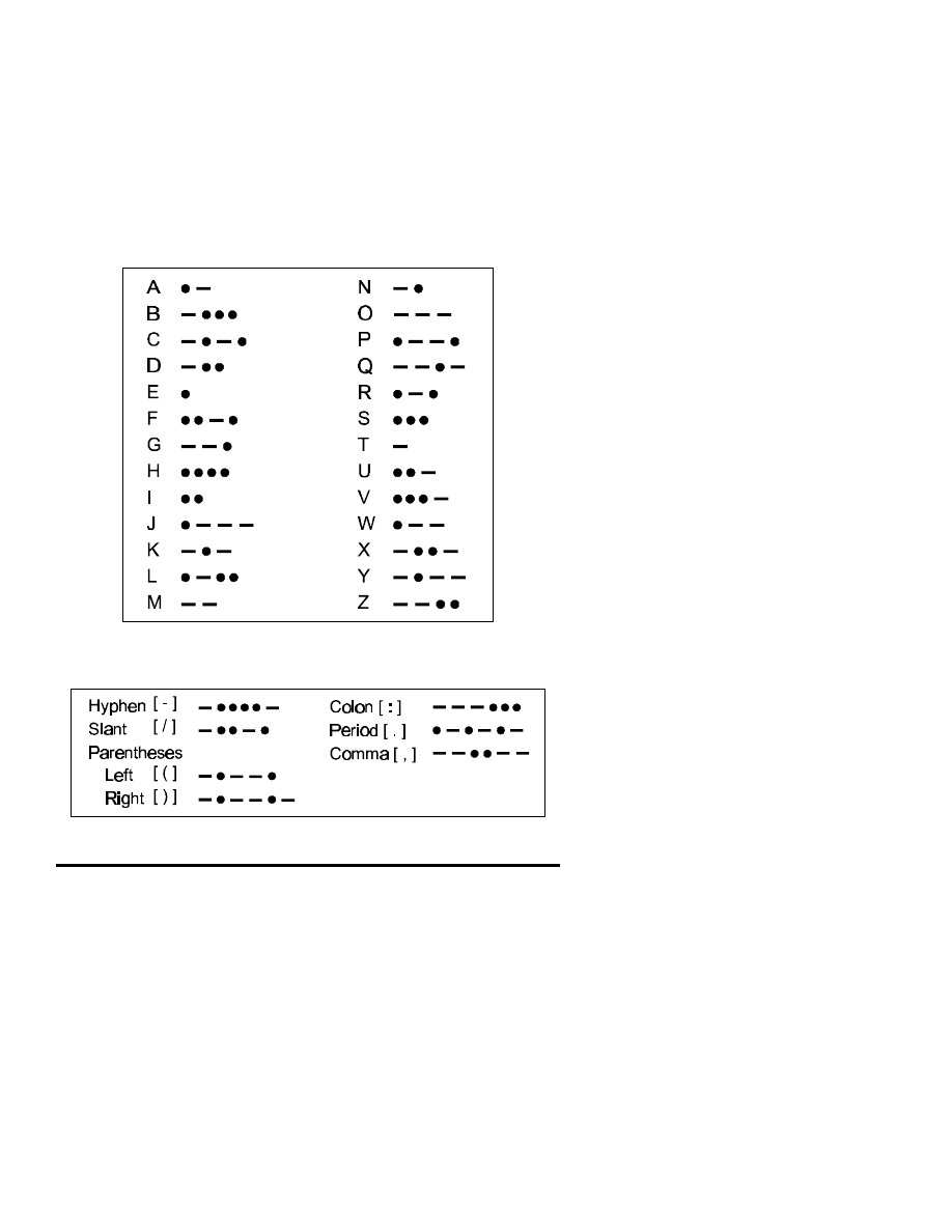
International Morse Code
MCRP 2-15.3B
Reconnaissance Reports Guide
151
International Morse
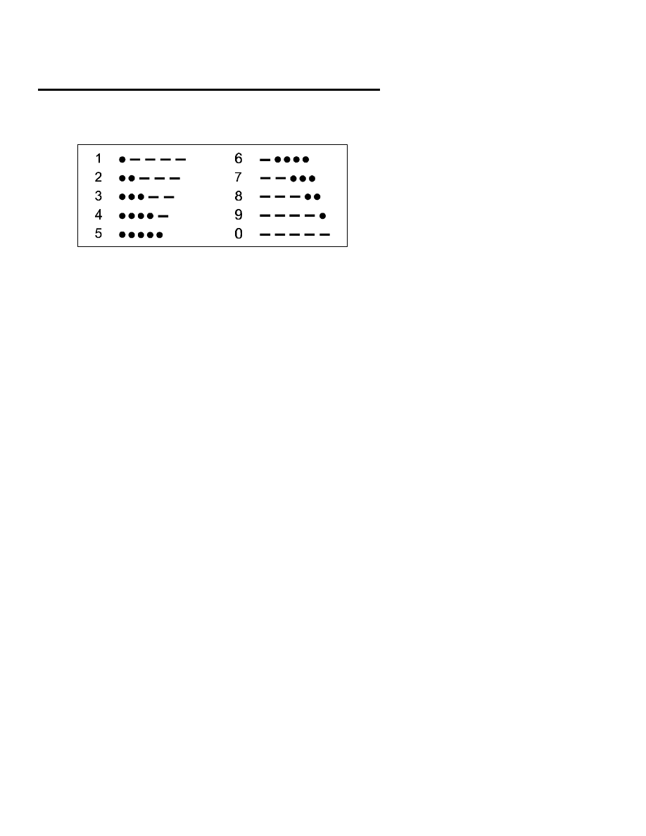
152
International Morse Code
MCRP 2-15.3B
Reconnaissance Reports

Sample Brevity Matrix
Effective from 980101 to 980112
A
B
C
D
E
F
G
H
I
J
1
North
Use
UHF
Not
Serious
Truck
Grid
Bogey
on Net
Fastrope VAPI
Send
MRE
SPIE
2
Jeep
Low
Band
Use
VHF
Time
Check
Need
CAS
Need
ARTY
Send 40
mm
Comm.
Site
Trench
Line
E&E
3
Smith
2435
O+
Jones
9735
O-
Assem.
Area
No. of
Troops
Troops
Dug In
Para.
Resupp.
Needed
NATO
Format
CH-46 Adams
0274
A+
Ottis
7395
AB+
4
3rd
Team
Insert
Compl
.
South
Extract
Time
At Obj
.
Abort
Mission
Hot LZ
Flash
HMMWV Observe
5
Priority
Foot
120’
Rope
Letters
BDA
Chem.
Lights
Man
injured
UH1N
West
Comm.
Change
6
High
Band
Scuba
Today’s
Freq
.
CH-53
Send
5.56LK
Linkup
Aborted
On the
Move
Insert.
Compl
.
2nd Team Extract
Grid
7
1st
Team
AT ORP No.
of
Troops
Helo.
Cast
Send
Batt
.
Cache
Location
More To
Follow
Time
Check
Send 5.56 No-
Fire
Area
8
UH-60
DZREP ALZREP POSREP Alt. Freq. SPOT-
REP
East
DELTA-
REP
BRIDGE-
REP
TUNNEL-
REP
9
Area
Recon
.
FORD-
REP
Check-
point
SITREP
Ambush Point
Recon
.
Observe Halt
Move
to
HQ
Element
10
Need
Batt.
Type
Bunker
Low
Band
Need
Camera
Film
Send
Frag.
Grenade
Emerg.
Extract
Photo
Grid
Strobe Naval
Gunfire
Linkup
Note: This should be read up then to the right. An example is, “A1E this
is D3K, 4D over.” (What time is extract?) “D3K this is A1E, 0700 out.”
(0700.)
MCRP 2-15.3B
Reconnaissance Reports
Guide

Brevity Matrix Information
The following is a sampling of items of information or events that could
be included in a brevity matrix. Use only those items that pertain to a par-
ticular reconnaissance patrol to avoid filling the brevity matrix with infor-
mation that is of no use.
Platoon
1st team
2nd team
3rd team
Insertion complete
Extraction complete
Mission
Extraction time
Extraction grid
compromised
Use VHF
Use HF
Use alternate
frequency
Need emergency
On the move
More to follow
extraction
Numbers 0-9
North
South
East
West
Abort mission
Mission complete
All North Atlantic
Cache location
Treaty Organization
(NATO) formats
Conduct linkup
Linkup aborted
Flash
Priority
Routine
Need resupply
154
Sample Brevity Matrix
MCRP 2-15.3B
Reconnaissance Reports

At objective
At objective
Awaiting
rally point (ORP)
extraction
In harbor site
In ambush site
Have no secure
CH-46
CH-53
UH-60
Rappel
Fastrope
SPIE
High-mobility,
Truck
Jeep
multipurpose
wheeled vehicle
(HMMWV)
E&E
Restrictive fire area
No-fire area
Conduct of fire net
Troops in open
Troops dug in
BDA
Trench line
Number of troops
120-foot rope
Observer
Parachute
Letters
High band
Low band
Moving to check-
Need camera film
Air panels
point number
Chemiluminescent
Scuba
Helocast
lights
MCRP 2-15.3B
Reconnaissance Reports
Guide

Foot
Need fuel
Visual approach
path indicator
(VAPI)
Communications
Assembly area
Stand by to control
site
Communications
Zulu time
Time check
change
156
Sample Brevity Matrix
MCRP 2-15.3B
Reconnaissance Reports

Acronyms
ALZ . . . . . . . . . . . . . . . . . . . . . . . . . . . . . . . . . . . . . . . . . . . . . . . . aircraft landing zone
ALZREP . . . . . . . . . . . . . . . . . . . . . . . . . . . . . . . . . . . . aircraft landing zone report
AMSL . . . . . . . . . . . . . . . . . . . . . . . . . . . . . . . . . . . . . . . . . . . . . above mean sea level
ART . . . . . . . . . . . . . . . . . . . . . . . . . . . . . . . . . . . amphibious reconnaissance team
BEACHREP . . . . . . . . . . . . . . . . . . . . . . . . . . . . . . . . . . . . . . . . beach survey report
BOB . . . . . . . . . . . . . . . . . . . . . . . . . . . . . . . . . . . . . . . . . . . . . . . . . . . . . . back of beach
BOMREP . . . . . . . . . . . . . . . . . . . . . . . . . . . . . . . . . . . . . . . . . . . . . . . bombing report
BRIDGEREP . . . . . . . . . . . . . . . . . . . . . . . . . . . . . . . . . . . . . . . . . . . . . . bridge report
CASREP . . . . . . . . . . . . . . . . . . . . . . . . . . . . . . . . . . . . . . . . . . . . . . . . . casualty report
CATF . . . . . . . . . . . . . . . . . . . . . . . . . . . . . . . commander, amphibious task force
CEOI . . . . . . . . . . . . . . . . . . comminications-electronics operating instructions
CLF . . . . . . . . . . . . . . . . . . . . . . . . . . . . . . . . . . . . . . . . . . . commander, landing force
CONBEREP . . . . . . . . . . . . . . . . . . confirmatory beach reconnaissance report
CONTACREP . . . . . . . . . . . . . . . . . . . . . . . . . . . . . . . . . . . . . . . . . . . . contact report
CW . . . . . . . . . . . . . . . . . . . . . . . . . . . . . . . . . . . . . . . . . . . . . . . . . . . . continuous wave
DACT . . . . . . . . . . . . . . . . . . . . . . . digital automated communications terminal
DELTAREP . . . . . . . . . . . . . . . . . . . . . . . . . . . . . . . . . . . . . . . . river/estuary report
DP . . . . . . . . . . . . . . . . . . . . . . . . . . . . . . . . . . . . . . . . . . . . . . . . . . . . . . . . . . datum point
DTG . . . . . . . . . . . . . . . . . . . . . . . . . . . . . . . . . . . . . . . . . . . . . . . . . . . . date-time group
DZREP . . . . . . . . . . . . . . . . . . . . . . . . . . . . . . . . . . . . . . . . . . . . . . . . drop zone report
E&E . . . . . . . . . . . . . . . . . . . . . . . . . . . . . . . . . . . . . . . . . . . . . . . . . evasion and escape
EEI . . . . . . . . . . . . . . . . . . . . . . . . . . . . . . . . . . . . . . essential element of information
MCRP 2-15.3B
Reconnaissance Reports
Guide

FIRREP . . . . . . . . . . . . . . . . . . . . . . . . . . . . . . . . . . . . frequency interference report
FLASHREP . . . . . . . . . . . . . . . . . . . . . . . . . . . . . . . . . . . . . . . . . . flash/action report
FMFM . . . . . . . . . . . . . . . . . . . . . . . . . . . . . . . . . . . . . . Fleet Marine Force manual
FMFRP . . . . . . . . . . . . . . . . . . . . . . . . Fleet Marine Force reference publication
FORDREP . . . . . . . . . . . . . . . . . . . . . . . . . . . . . . . . . . . . . . . . . . . . . river ford report
HC . . . . . . . . . . . . . . . . . . . . . . . . . . . . . . . . . . . . . . . . . . . . . . . . . . . . . . . . . white smoke
HELLSREP . . . . . . . . . . . . . . . . . . . . . . . . . . . . . . . . helicopter landing site report
HF . . . . . . . . . . . . . . . . . . . . . . . . . . . . . . . . . . . . . . . . . . . . . . . . . . . . . . . high frequency
HMMWV . . . . . . . . . . . . . . . . . . high-mobility, multipurpose wheeled vehicle
IP . . . . . . . . . . . . . . . . . . . . . . . . . . . . . . . . . . . . . . . . . . . . . . . . . . . . . . . . . . impact point
IR . . . . . . . . . . . . . . . . . . . . . . . . . . . . . . . . . . . . . . . . . . . . . . information requirement
KIA . . . . . . . . . . . . . . . . . . . . . . . . . . . . . . . . . . . . . . . . . . . . . . . . . . . . . . killed in action
MCRP . . . . . . . . . . . . . . . . . . . . . . . . . . . . . . Marine Corps reference publication
MHW . . . . . . . . . . . . . . . . . . . . . . . . . . . . . . . . . . . . . . . . . . . . . . . . . mean high water
MIA . . . . . . . . . . . . . . . . . . . . . . . . . . . . . . . . . . . . . . . . . . . . . . . . . . . . missing in action
MIJI . . . . . . . . . . . . . . . . . . . . meaconing, intrusion, jamming, and interference
MIJIREP . . . . . . . . meaconing, intrusion, jamming, and interference report
MLW . . . . . . . . . . . . . . . . . . . . . . . . . . . . . . . . . . . . . . . . . . . . . . . . . . . mean low water
MORTREP . . . . . . . . . . . . . . . . . . . . . . . . . . . . . . . . . . . . . . . . . . . . mortaring report
NAR . . . . . . . . . . . . . . . . . . . . . . . . . . . . . . . . . . . . . . . . . . . . . . . . . . not able to record
NATO . . . . . . . . . . . . . . . . . . . . . . . . . . . . . . North Atlantic Treaty Organization
NBC . . . . . . . . . . . . . . . . . . . . . . . . . . . . . . . . . . . nuclear, biological, and chemical
NBCREP . . . . . . . . . . . . . . . . . . . . . . . . nuclear, biological, and chemical report
NC . . . . . . . . . . . . . . . . . . . . . . . . . . . . . . . . . . . . . . . . . . . . . . . . . . . . . . . . . . . . no change
OIR . . . . . . . . . . . . . . . . . . . . . . . . . . . . . . . . . . . . . . . other information requirement
OPORD . . . . . . . . . . . . . . . . . . . . . . . . . . . . . . . . . . . . . . . . . . . . . . . . . operation order
158
Acronyms
MCRP 2-15.3B
Reconnaissance Reports

ORP . . . . . . . . . . . . . . . . . . . . . . . . . . . . . . . . . . . . . . . . . . . . . . . . objective rally point
POW . . . . . . . . . . . . . . . . . . . . . . . . . . . . . . . . . . . . . . . . . . . . . . . . . . . . prisoner of war
RAILREP . . . . . . . . . . . . . . . . . . . . . . . . . . . . . . . . railroad reconnaissance report
ROUTEREP . . . . . . . . . . . . . . . . . . . . . . . . . . . . . . . . . . . . . . route and road report
SALUTE . . . . . . . . . . . . . . . . . . . size, activity, location, unit, time, equipment
SHELREP . . . . . . . . . . . . . . . . . . . . . . . . . . . . . . . . . . . . . . . . . . . . . . . shelling report
SITREP . . . . . . . . . . . . . . . . . . . . . . . . . . . . . . . . . . . . . . . . . . . . . . . . . situation report
SPIE . . . . . . . . . . . . . . . . . . . . . . . . . . . . . . special patrol insertion and extraction
SPOTREP . . . . . . . . . . . . . . . . . . . . . . . . . . . . . . . . . . . . . . . . enemy sighting report
STANAG . . . . . . . . . . . . . . . . . . . . . . . . . . . . . . . . . . . . standardization agreement
SURFREP . . . . . . . . . . . . . . . . . . . . . . . . . . . . . . . . . . . . . . . surf observation report
TAP . . . . . . . . . . . . . . . . . . . . . . . . . . . . . . . . . . . . . . . . . . . . . . . target approach point
TUNNELREP . . . . . . . . . . . . . . . . . . . . . . . . . . . . . . . . . . . . . . . . . . . . . . tunnel report
UHF . . . . . . . . . . . . . . . . . . . . . . . . . . . . . . . . . . . . . . . . . . . . . . . . ultrahigh frequency
ULLA . . . . . . . . . . . . . . . . . . . . . . . . . . . . . . . . . . . . . . . . . . ultra-low-level approach
VAPI . . . . . . . . . . . . . . . . . . . . . . . . . . . . . . . . . . . . . visual approach path indicator
VHF . . . . . . . . . . . . . . . . . . . . . . . . . . . . . . . . . . . . . . . . . . . . . . . . very high frequency
WIA . . . . . . . . . . . . . . . . . . . . . . . . . . . . . . . . . . . . . . . . . . . . . . . . . wounded in action
WLTS . . . . . . . . . . . . . . . . . . . . . . . . . . . . . . . . . waterline at the time of sounding
WP . . . . . . . . . . . . . . . . . . . . . . . . . . . . . . . . . . . . . . . . . . . . . . . . . . . . white phosphorus
MCRP 2-15.3B
Reconnaissance Reports
Guide

References
Fleet Marine Force Manual (FMFM) 3-30, Communications
Fleet Marine Force Reference Publication (FMFRP) 3-34, Field Antenna
Handbook (under revision as MCRP 6-22D)
Standardization Agreement (STANAG) 3570, Drop Zones and Extrac-
tion Zones—Criteria and Marking
MCRP 2-15.3B
Reconnaissance Reports
Guide
Document Outline
- Cover
- To Our Readers
- E R R A T U M
- CHANGE 1
- Foreword
- Table of Contents
- General Information
- Terrain Recon for ALZ
- Beach Survey Report
- Bridge Report
- Casualty Report Worksheet
- Confirmatory Beach Report
- Contact Report
- River/Estuary Report
- Drop Zone Report
- Flash/Action Report
- Frequency Interference Report
- River Ford Report
- Helo Landing Site Report
- Meaconing, Intrusion, Jamming, and Interface Report
- NBC Report
- Railroad Recon Report
- Route and Road Report
- Standard Sheling Report
- Situation Report and Worksheet
- Enemy Sighting Report
- Surf Observation Report
- Tunnel Report
- International Morse Code
- Sample Brevity Matrix
- Acronyms
- References
Wyszukiwarka
Podobne podstrony:
011231 [Dating Seduction] Wayne Ross The complete guide to attracting women Bonus reports
MCRP 3 11 2A Marine Troop Leaders Guide
guide camino aragones pl
PNADD523 USAID SARi Report id 3 Nieznany
Herbs for Sports Performance, Energy and Recovery Guide to Optimal Sports Nutrition
Meezan Banks Guide to Islamic Banking
NLP for Beginners An Idiot Proof Guide to Neuro Linguistic Programming
freespan spec guide
Eaton VP 33 76 Ball Guide Unit Drawing
Herbs to Relieve Headaches Keats Good Herb Guide
50 Common Birds An Illistrated Guide to 50 of the Most Common North American Birds
Configuration Guide WAN Access(V100R006C00 02)
installation guide
iR Shell 3 9 User Guide
1970 01 01 Kant039s 039perpetual peace039 utopia or political guide
M12 Oncore Users Guide Supplement
Ludzie najsłabsi i najbardziej potrzebujący w życiu społeczeństwa, Konferencje, audycje, reportaże,
REPORTAŻ (1), anestezjologia i intensywna terapia
więcej podobnych podstron