
Initial Print Date: 10/06
Table of Contents
Subject
Page
New Transmissions for E70 . . . . . . . . . . . . . . . . . . . . . . . . . . . . . . . . . . . .5
Electronic Transmission Control . . . . . . . . . . . . . . . . . . . . . . . . . . . . . . . . . .8
Gear Selector Lever (GWS) . . . . . . . . . . . . . . . . . . . . . . . . . . . . . . . . . . . . .10
Operation and Functions . . . . . . . . . . . . . . . . . . . . . . . . . . . . . . . . . . . .10
Manual Gate, Sport Program (M/S) . . . . . . . . . . . . . . . . . . . . . . . . . . . .13
Parking Lock "P" . . . . . . . . . . . . . . . . . . . . . . . . . . . . . . . . . . . . . . . . . . . .13
Automatic Downshift from "M/S" . . . . . . . . . . . . . . . . . . . . . . . . . . . . .13
Interface to EGS . . . . . . . . . . . . . . . . . . . . . . . . . . . . . . . . . . . . . . . . . . . .14
Definition of Messages . . . . . . . . . . . . . . . . . . . . . . . . . . . . . . . . . . . .14
Safe Status for Sending . . . . . . . . . . . . . . . . . . . . . . . . . . . . . . . . . . .14
Evaluating the P-button . . . . . . . . . . . . . . . . . . . . . . . . . . . . . . . . . . . . . .16
Evaluating the Unlock Button . . . . . . . . . . . . . . . . . . . . . . . . . . . . . . . . .17
Emergency Release of Parking Lock . . . . . . . . . . . . . . . . . . . . . . . . . . . . .18
GA6HP19/26TU Gearbox . . . . . . . . . . . . . . . . . . . . . . . . . . . . . . . . . . . . . .19
Casing and Intermediate Plate . . . . . . . . . . . . . . . . . . . . . . . . . . . . . . . .19
Converter lockup clutch connection stages . . . . . . . . . . . . . . . . . . . .22
Target gear allocation dependent on accelerator pedal gradient . .24
Shift Speed Characteristics . . . . . . . . . . . . . . . . . . . . . . . . . . . . . . . . . .26
Torque Intervention . . . . . . . . . . . . . . . . . . . . . . . . . . . . . . . . . . . . . . . . .26
LIN-Bus Module . . . . . . . . . . . . . . . . . . . . . . . . . . . . . . . . . . . . . . . . .26
E70 Transmissions
Revision Date:

Subject
Page
Torque Converter Control . . . . . . . . . . . . . . . . . . . . . . . . . . . . . . . . . . . .27
Variable Cooling Oil Flow . . . . . . . . . . . . . . . . . . . . . . . . . . . . . . . . . .27
Emergency Release of Parking Lock . . . . . . . . . . . . . . . . . . . . . . . . . .30

Subject
Page
BLANK
PAGE

4
E70 Transmissions
Transmissions
Model: E70
Production: From Start of Production
After completion of this module you will be able to:
• Describe changes to E70 Automatic Transmissions
• Understand GWS Operation
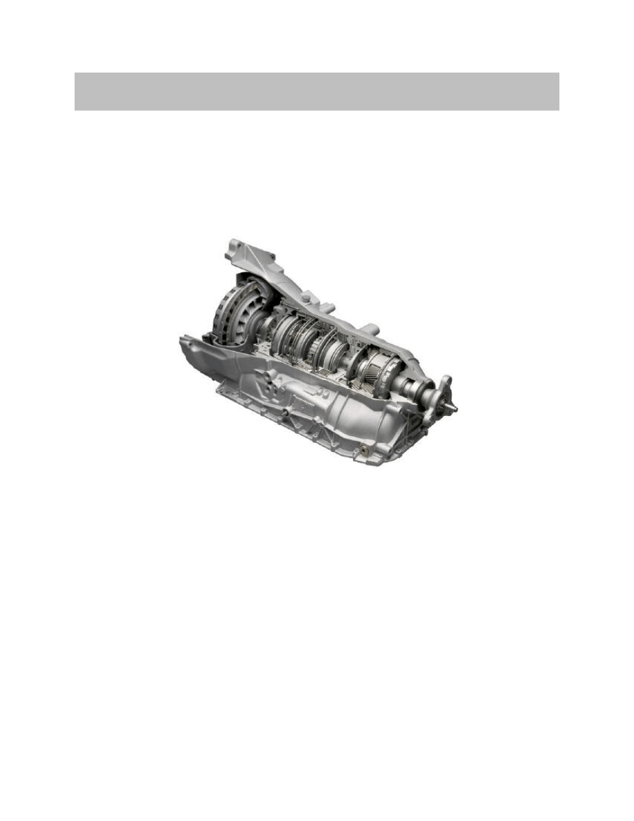
The GA6HPTU gearbox is a further development of the known automatic gearbox
GA6HP. The re-engineered automatic gearbox provides a distinct boost in dynamics
while at the same time improving fuel consumption and pollutant emission.
The E70 is equipped with an electric gearshift system similar to the system in the E65.
In this case, however, the automatic gearbox is not operated from a steering column stalk
but rather from a selector lever that is located in the standard position on the center
console.
The shift pattern is largely modeled on a conventional gearshift with mechanical link to
the automatic gearbox. The electronic transmission control (EGS) has been adapted to
the changes/modifications.
This reference manual only deals with the changes and modifications to the GA6HP
gearbox.
Changes
The automatic gearbox GA6HPTU for the E70 has been reengineered in terms of the
following points:
• Torque converter with turbine-torsion damper
• Clutch E
• Adapted electronic transmission control (EGS)
• Faster hydraulics through new pressure regulator
• Electric gearshift
5
E70 Transmissions
New Transmissions for E70
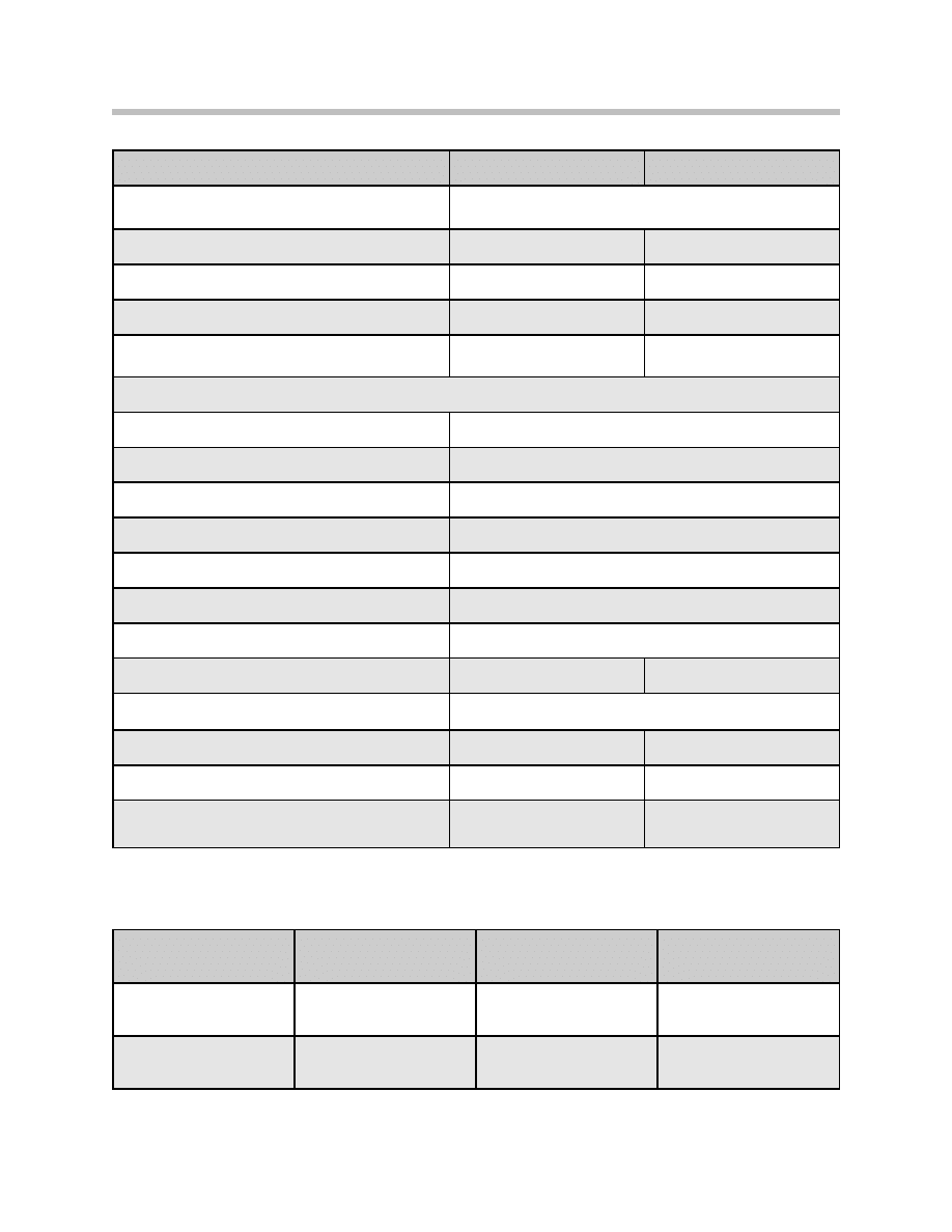
Technical Data
Gearbox Variant
6
E70 Transmissions
GA6HP19TU
GA6HP26TU
Type of gearbox
Passenger vehicle automatic gearbox with 6 forward speeds
and 1 reverse gear in standard arrangement.
Transmission output in [kW]
225
300
Transmission output in [Nm]
400
650
Torque converter
W240R TTD
W270RH-4GWK TTD
Maximum permissible continuous speed of
torque converter in rpm
7000
7000
Transmission Ratios
1st gear
4.171
2nd gear
2.340
3rd gear
1.521
4th gear
1.143
5th gear
0.867
6th gear
0.691
Reverse
3.403
Gearbox weight (kg) including oil
77.0
92.0
Control
Electro-hydraulic with
electronic transmission control
Towing range
500 km at up to 80 km/h
500 km at up to 80 km/h
Maximum uphill/downhill gradient while driving
50%
50%
Maximum uphill gradient, starting off
(in forward or reverse)
32%
32%
Model
Engine
Transmitted torque
GA6HP19TU
X5 3.0i (E70)
N52B30O1
400 Nm
GA6HP26TU
X5 4.8i (E70)
N62B48O1
650 Nm

7
E70 Transmissions
NOTES
PAGE
8
E70 Transmissions
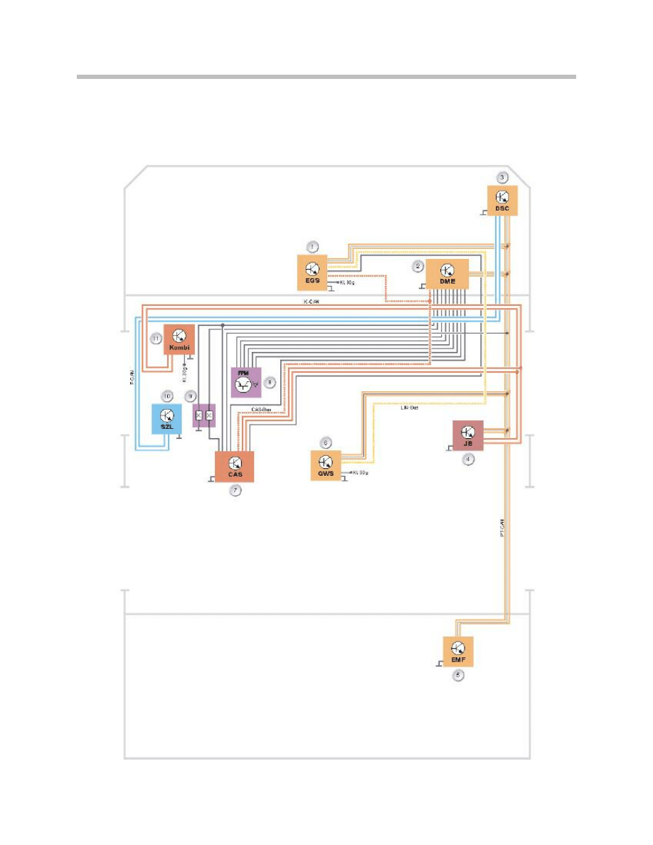
Electronic Transmission Control
The following diagram shows the interconnection of the electronic transmission control
with the gear selector lever and the interfaces in the vehicle.

9
E70 Transmissions
Index
Explanation
Index
Explanation
1
EGS control module
7
Car Access System (CAS)
2
DSC control module
8
Accelerator pedal module
3
ECM (DME)
9
Brake light switch
4
Junction Box control unit
10
Steering column switch cluster
5
EMF
11
Instrument cluster
6
Gear Selector Lever (GWS)
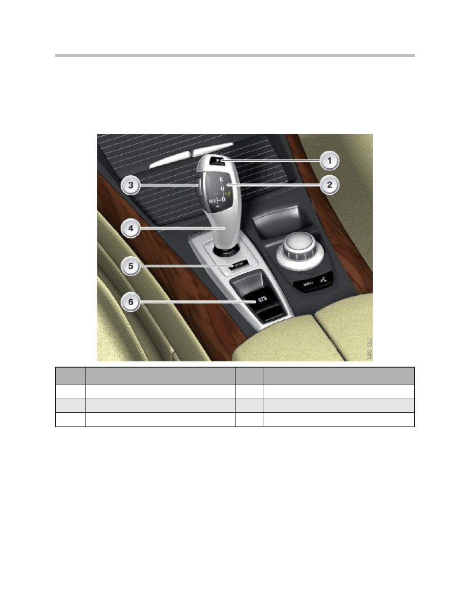
Gear Selector Lever (GWS)
The automatic gearbox in the E70 is operated by means of an electric gearshift system.
This system is already known from the E65. Unlike in the E65, the gear selector lever in
the E70 is not on the steering column but rather in the usual position on the center
console.
The gear selector lever consists of the selector lever itself with indicator and the housing
with the control unit.
Operation and Functions
The shift pattern is modeled on the conventional BMW automatic gearbox. It features an
automatic gate and a manual gate. Only the parking lock is not engaged by pushing the
selector lever forward but rather by pressing a button at the top of the selector lever.
The selector lever is monostable in both gates (manual and automatic). This means, after
being moved, the selector lever always returns to its initial position. In the manual gate
this is the same as automatic gearboxes with Steptronic.
10
E70 Transmissions
Index
Explanation
Index
Explanation
1
Parking lock button
4
Selector lever
2
Indicator
5
Sport button for EDC
3
Unlock button
6
Parking brake

In addition to the one-touch function, the selector lever can also be pushed in the
automatic gate. This is comparable to the function of the direction indicator stalk in the
E90.
The drive range is changed by tapping the selector lever. A direct change from "D" to "R"
or vice versa can be achieved by tapping the selector lever twice or by pushing the lever.
The Unlock button is located on the left-hand side of the selector lever.
Haptic Locks
Electrically controlled, mechanically actuated locks ensure that the selector lever can only
be pushed in the logically possible direction, e.g. only forward from "D".
These locks are also used for the shift lock function, i.e. when a drive range can be
engaged only by pressing the unlock button. The selector lever is not locked if it is
necessary to depress the service brake in order to engage a drive range for example.
Instead, the function is not executed and a message appears in the on-board monitor
indicating: "Press brake to engage gear". The lock for moving the lever forward differs
from the lock for moving the lever back. The forward lock is a double lock and can
therefore prevent over-pressing the lever when a flick is possible.
In contrast to this, the backward lock can only completely prevent the movement.
Whenever the selector lever can be pulled back, it can also be pulled back beyond the
stop even if it no longer has a function.
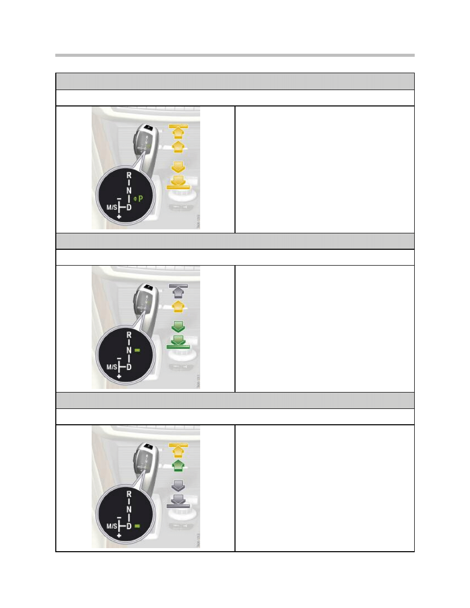
The following graphics illustrate the operating options. The arrows indicate:
• Yellow arrow - Movement possible only with unlock button pressed.
• Grey arrow - Movement not possible.
• Green arrow - Movement possible.
11
E70 Transmissions
12
E70 Transmissions
Operating options of the gear selector lever
Shift from “P”
A drive range or neutral "N" can be engaged from "P"
only with the unlock button pressed and the service
brake depressed.
• Fully pressing forward selects the drive stage "R".
• Pressing forward selects the neutral position "N".
• Pressing back selects the drive range "D".
• Fully pressing back is possible but has no function
as “D" has already been engaged at this time.
The selector lever is not locked if the brake pedal is not
locked - movement is possible but the EGS will not
engage the drive range or "N".
Operating options of the gear selector lever
Shift from “N”
• Pressing forward selects the drive stage "R". This
is possible only with the unlock button pressed.
• Pressing back selects the drive range "D".
• Fully pressing back is possible but has no function
as "D" has already been engaged at this time.
Engaging a drive range from "N" at a speed < 5 km/h is
possible only with the service brake pressed. The selec-
tor lever, however, is not locked.
At a speed > 5 km/h, the drive range can be engaged in
the corresponding direction without having to press the
brake pedal.
Operating options of the gear selector lever
Shift from “D”
• Fully pressing forward selects the drive stage "R".
This is possible only with the unlock button
pressed. The EGS engages drive range "R" only
when the service brake is pressed and the speed
is < 5 km/h. Otherwise "N" is selected. The selec-
tor lever is therefore not locked.
• Pressing forward selects the neutral position "N".
• Pressing back is prevented by a lock.
• Pressing to the left selects the "M/S" gate.
Manual Gate, Sport Program (M/S)
As before, the sport program is engaged by shifting the selector lever to the left.
The selector lever locks in this position. The sport program can only be engaged
from "D".
Parking Lock "P"
The parking lock "P" is engaged by pressing the button at the top of the selector lever
when the vehicle speed is < 2 km/h.
The gearbox also automatically selects "P" as soon as the engine is turned off and "N" is
not engaged.
Automatic Downshift from "M/S"
The automatic downshift function returns the selector lever from the "M/S" gate to the
automatic gate.
This occurs, for example, when the EGS signals gearbox position "P" as is the case when
the engine is shut down or the "P" button is pressed.
The selector lever remains locked in the "M/S" gate only if "S" or "M" mode is actually
active while driving in forward direction or the automatic downshift is defective or receives
no power supply.
5 downshift attempts are executed at intervals of approximately 5 seconds if the selector
lever is blocked from the outside, e.g. by an object.
If the downshift cannot be executed, the check control message: "Move selector lever
back into automatic gate" appears after two attempts. A fault code memory entry is
generated.
13
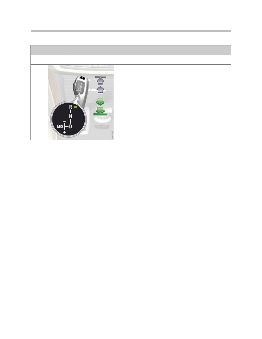
E70 Transmissions
Operating options of the gear selector lever
Shift from “R”
• Pressing forward is prevented by a lock.
• Pressing back selects the neutral position "N".
• Pressing fully back selects the drive range "D".
The EGS engages drive range "D" only when the service
brake is pressed. Otherwise "N" is selected. The selec-
tor lever is therefore not locked.
Interface to EGS
With the aim of increasing availability, the gear selector lever position is sent via the
PT-CAN and LIN-bus. This means, a signal is still sent to the EGS should the PT-CAN
fail. This is not necessary for safety reasons.
Safety is guaranteed by neutrally complementary signals or alive counters. The gear
selector switch (GWS) is woken by a high-level on the PT-CAN wake-up line. The GWs
itself has no active wake-up capabilities.
Definition of Messages
Communication
The data blocks are sent both event controlled as well as cyclically on the PT-CAN.
They are sent only cyclically on the LIN-bus. Complementary signals are sent for the
purpose of securing the transmission link.
These signals are compared with the actual signals in the respective receive control unit.
Alive counters serve the purpose of detecting defects in the transmit control unit.
The alive counter in the respective receive control unit is monitored to establish whether
it remains at a constant value.
A plausibility check between the signals of the PT-CAN transmission and of the LIN-bus
does not take place in the receive control unit.
Safe Status for Sending
If a GWS-internal plausibility check determines that the position of the selector lever can
be transmitted incorrectly, the system assumes the safe status for sending the message
"Operation of gear selector lever".
Consequently, all signals of this message are sent invalid on the PT-CAN and the
LIN-bus. If it is not possible to ensure that the signals can be sent invalid, the sending of
these messages is completely deactivated.
14
E70 Transmissions
Interface
From
To
Message
PT-CAN
GWS
EGS
Gear selector lever operation
PT-CAN
EGS
GWS
Show gearbox data
LIN-bus
GWS
EGS
Gear selector lever operation
LIN-bus
EGS
GWS
Show gearbox data

Indicator in the Gear Selector Lever
The task of the indicator in the gear selector lever (GWS) is to reliably indicate the drive
range currently engaged. The indicator consists of the locator light that represents the
shift pattern and the function lighting. This comprises the various position LEDs that
indicate the drive range currently engaged.
The function lights in the gear selector lever are controlled by the "Indicate gearbox data"
message sent from the EGS. It is necessary to monitor the function lighting. For this
purpose, the indication is read back and compared with the required indication.
The indicator is active as soon as bus communication is active on the PT-CAN or the
LIN-bus.
Flashing of a Position LED
A position LED flashing draws the driver's attention to incorrect operation. The locator
lighting remains constant and does not flash. The flashing action is triggered by an EGS
signal. The frequency is 0.5 Hz.
Indicator Flashing Through Diagnosis
The entire function lighting can be made to flash at a frequency of 1 Hz for approximately
10 seconds by means of a diagnosis job for testing the indicator.
Secure Indicator Status
The indicator is a safety-relevant function so that incorrect indication must be prevented.
The system assumes the secure indicator status if the possibility of an incorrect
indication cannot be ruled out.
The function lighting is switched off for this purpose. The locator lighting remains
switched on.
Transfer to the secure status can be triggered by two events:
• Defective communication on the bus or
• An internal defect in the gear selector lever
The main transmission path to the EGS is the PT-CAN. If the "Display gearbox data"
message is not received correctly on the PT-CAN, the gear selector lever will change over
to the LIN-bus. If, after changing over to the LIN-bus, a fault is also detected on this
communication path, the system will assume the secure status. The plausibility check of
the LIN-bus is constantly executed in the background. If it is necessary to change over to
the LIN-bus in the event of a defect, it is possible to switch directly to the secure indicator
state if the system detects beforehand that there are problems with the communication
on the LIN-bus.
15
E70 Transmissions

A fault code entry is generated in response to changing over to the secure status due to
communication problems. This fault situation is irreversible. If the "Display gearbox data"
message is received correctly again, the indicator will be activated normally once again
after 2 seconds.
The gear selector lever immediately changes over to the secure indicator status if the
diagnostic function in the gear selector lever detects an implausibility regarding the
indicator.
In this case, a corresponding fault code entry is generated. This fault case is not
reversible until the next time the gear selector lever assumes sleep mode.
Park and Unlock Button
Evaluating the P-button
The P-button sends the driver's choice to apply the parking lock to the EGS.
• The P-button is read by means of two contacts in inverse logic.
• The two contacts are evaluated in separate logic and represented by the two signals
P1 and P2 independent of each other.
• Before being sent, the P2 signal is inverted in the gear selector lever.
• The two contacts in the gear selector lever are compared for diagnostic purposes.
A fault code entry is stored if different contacts are applied for longer than 2
seconds.
• An internal diagnostic function in the gear selector lever detects a defective contact
and enters a corresponding fault code in the fault code memory.
• The button sticking is detected when at least one contact is applied for longer than
2 minutes.
• The P1 and P2 signals are sent independent of each other on the PT-CAN and
redundantly on the LIN-bus to the EGS.
• Due to the confirmation tolerances, one signal can be sent as confirmed before the
other.
If the required conditions are met (speed, etc.), the EGS will engage the parking lock
when at least one signal (P1 and/or P2) was sent as confirmed.
16
E70 Transmissions

Evaluating the Unlock Button
The lock to shift to "R" or out of "P" is released by pressing the unlock button.
• The unlock button is read by means of two contacts in inverse logic.
• The two contacts in the gear selector lever are compared for diagnostic purposes.
A fault code entry is stored if different contacts are applied for longer than 2
seconds.
• An internal diagnostic function in the gear selector lever detects a defective contact
and enters a corresponding fault code in the fault code memory.
• Before being sent, the P2 signal is inverted in the gear selector lever.
• The button sticking is detected when at least one contact is applied for longer than
2 minutes.
• Both signals are sent on the PT-CAN and redundantly on the LIN-bus to the EGS as
soon as a contact is detected as confirmed.
Components
Sensors
The selector lever position is detected without contact with the aid of seven Hall sensors
for detecting the selector lever position in the longitudinal direction of the vehicle as well
as four Hall sensors for detecting the selector lever position in the transverse direction of
the vehicle.
In the event of one individual sensor failing, the software in the gear selector lever is still
capable of calculating the correct position of the selector lever.
Actuators
Three actuators are used. A motor with subsequently connected gear mechanism is
used for shifting out of the "M/S" gate and for the lock (inhibit) to "M/S".
A bi-directional spring-centered double magnet is used for the inhibit in "R" direction.
A single magnet with spring reset is used for the inhibit in "D" direction. The actuators
do not inhibit the shift to "R" and "D" in the case of fault or if no power is applied.
17
E70 Transmissions
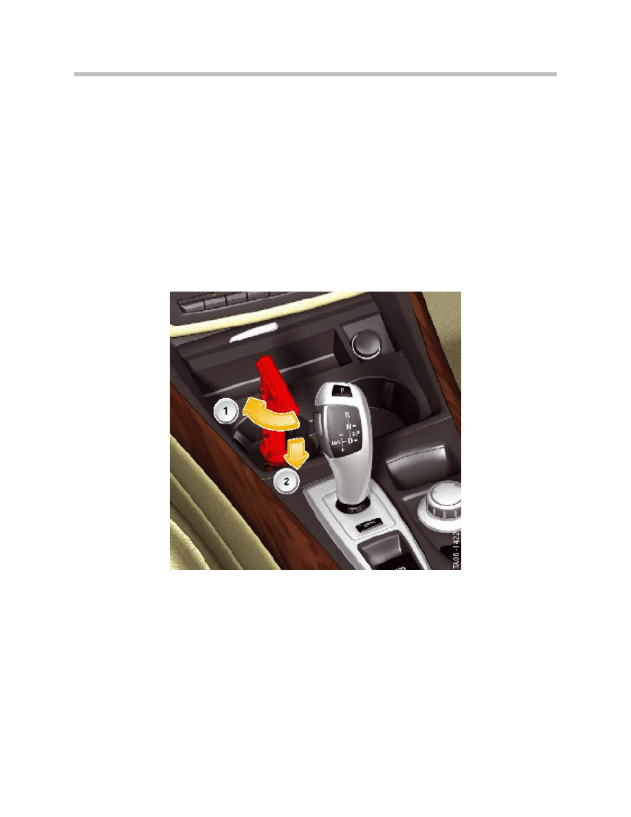
Emergency Release of Parking Lock
In the case of emergency (e.g. failure of the system voltage), the parking lock can be
released by correspondingly operating the emergency release.
To access the emergency release, the rubber inlay in the front cup holder is first removed
and then the cover released by turning in counter-clockwise direction. The emergency
release is now accessible.
The vehicle tool kit includes a handle for the emergency release. This handle is inserted
in the emergency release. The parking lock is released by turning in clockwise direction.
The emergency release is locked by pressing down on the handle. The handle for the
emergency release of the parking lock is also used for the emergency release of the
electro-mechanical parking brake.
In the event of the system voltage failing, first release the electro-mechanical parking
brake (EMF) as the handle remains in the emergency release.
Note: Do not remove the handle from the emergency release while the
vehicle is being towed as this will reengage the parking lock.
Releasing the parking lock with the emergency release generates
a fault code entry in the EGS: "Parking lock release error"
18
E70 Transmissions
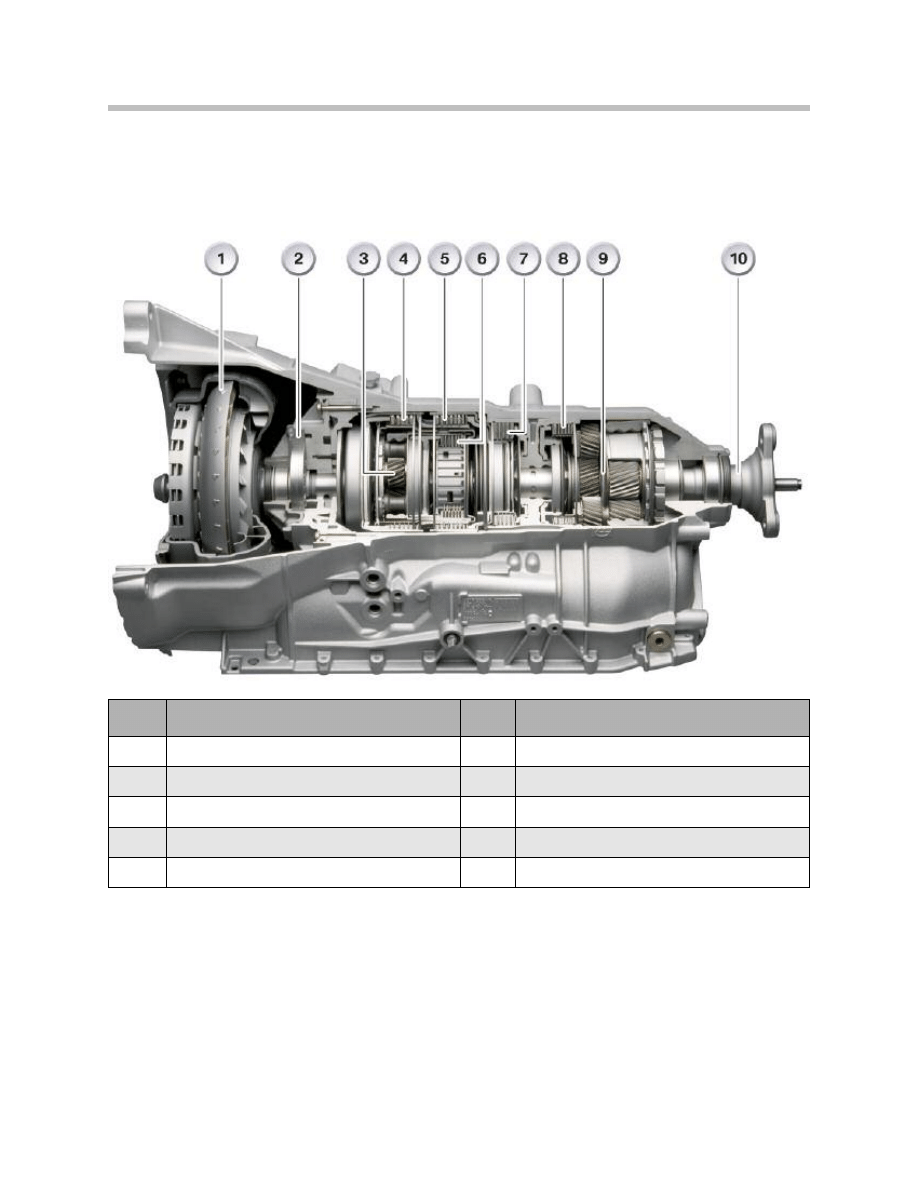
GA6HP19/26TU Gearbox
The gearbox has been optimized in terms of gearshift comfort, dynamics and reducing
fuel consumption.
Casing and Intermediate Plate
The casing and the intermediate plate of the GA6HPTU gearbox have been adapted to
the new hydraulic unit and the resulting channel arrangement.
The GA6HPTU gearbox is a reengineered version of the 6-speed automatic gearbox that
was introduced in the E65 and since then used in all model series.
The modifications are specifically targeted at achieving higher dynamics, lower fuel
consumption and reduced pollutant emissions.
19
E70 Transmissions
Index
Explanation
Index
Explanation
1
Torque converter with TTD and lock-up clutch
6
Drive clutch E
2
Oil pump
7
Brake clutch C
3
Single gear train
8
Brake clutch D
4
Drive clutch A
9
Double gear train
5
Drive clutch B
10
Output flange
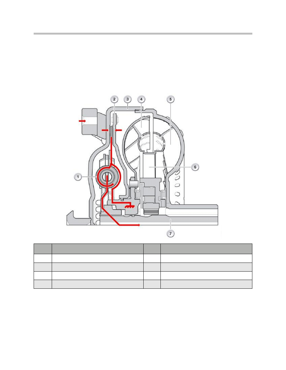
Torque Converter
A new torque converter is used in the GA6HPTU gearbox. This torque converter
contains an effective torsion damper system known as the turbine-torsion damper (TTD).
This is a classic torsion damper, in which the primary side (engine side) is fixed to the tur-
bine wheel of the torque converter. This arrangement brings about an increase in the
flywheel mass on the primary side thus distinctly improving the damping properties.
20
E70 Transmissions
Index
Explanation
Index
Explanation
1
Annular spring plate
5
Impeller
2
Converter lockup clutch piston
6
Stator
3
Converter housing
7
Gearbox input shaft
4
Turbine wheel

With the converter lockup clutch disengaged, i.e. in converter mode, the power flow from
the turbine wheel does not take place in the usual manner to the transmission input shaft.
The turbine wheel transmits the power to the primary side of the torsion damper.
The secondary side of the turbine-torsion damper is connected to the input shaft of the
gearbox.
Since the converter transmits no vibrations, the torsion damper need not perform any
damping work. In this case it functions virtually as a rigid transmission element.
When the converter lockup clutch is engaged, the power is transmitted directly from the
clutch to the primary side of the turbine torsion damper. Due to the rigid connection to
the turbine wheel of the torque converter, the flywheel mass is increased on the primary
side.
The power is transmitted via the turbine-torsion damper to the input shaft of the gearbox.
Torsional vibration is filtered out very effectively.
With this system, it is possible to engage (close) the converter lockup clutch much earlier
without having to take any deterioration in comfort into account. This arrangement
directly connects the gearbox to the engine, resulting in a boost in dynamics as well as a
reduction in fuel consumption and exhaust emissions.
Clutches
The clutch E has been reworked. The clutch E is a drive clutch that connects the ring
gear of the single planetary gear train with the long planet gear of the double planetary
gear train.
It is closed in fourth, fifth and sixth gear. The lining of clutch E is made from a new
material that offers greater stability in terms of vibration and squeaking.
21
E70 Transmissions
Mechatronics Module
Converter lockup clutch connection stages
The ability of the new torque converter to dampen torsional vibration with the turbine
torsion damper is used to keep the converter lockup clutch closed as often as possible.
This means the gearbox is connected directly to the engine.
A general statement as to under what conditions the converter lockup clutch is
disengaged (open) or engaged (closed) can still not be made as this depends on very
many factors.
• Load choice signal (accelerator pedal position)
• Engine load status
• Vehicle speed
• Transmission fluid temperature
• Selected gearshift program
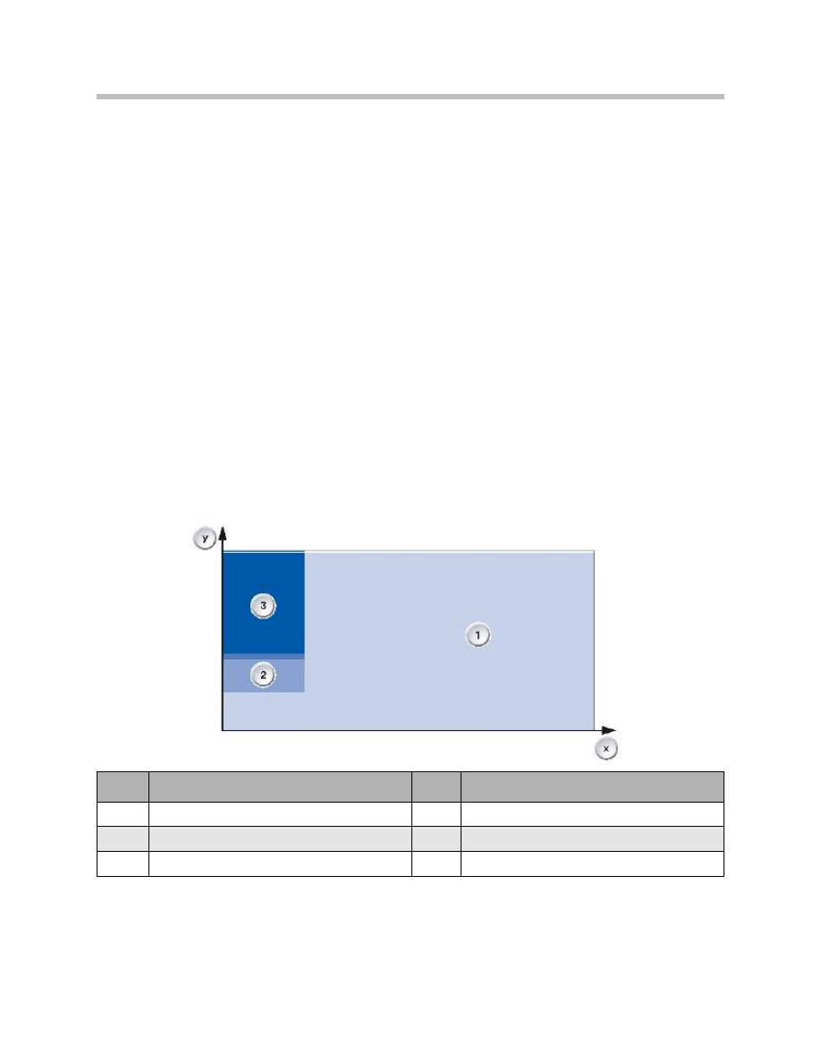
The following graphic, however, shows the strategy as to when the converter lockup
clutch should be disengaged or engaged, i.e. when converter lockup clutch control is
required.
As the previous graphic illustrates, the converter lockup clutch is engaged (closed) (1)
over large ranges during vehicle operation. The clutch is only controlled in the low speed
ranges (2 + 3). Greater slip (3) is permitted in response to high load requirements in
order to avoid the generation of noise and vibration.
22
E70 Transmissions
Index
Explanation
Index
Explanation
X
Vehicle speed
2
Low slip
Y
Accelerator pedal position
3
High slip
1
Converter lockup clutch engaged
When the load requirement is low, the slip at the converter lockup clutch is also kept low
to enable a more direct connection. For reasons of simplicity, the previous graphic does
not illustrate when the converter lockup clutch is open, e.g. when the vehicle is stationary
or when starting off.
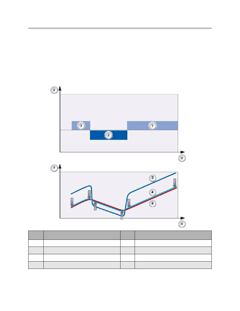
The driver experiences the direct link from the engine to the gearbox as a distinct boost in
dynamics. Output speed follows the engine speed when the foot is pressed down and
lifted off the accelerator. There is no familiar jump in engine speed as illustrated in the
following graphic.
23
E70 Transmissions
Index
Explanation
Index
Explanation
X
Time
2
Slip
Y
Accelerator pedal position
3
Previously: engine speed with TCC slip
Z
Engine speed
4
New: engine speed with direct connection
1
Load
5
Output speed
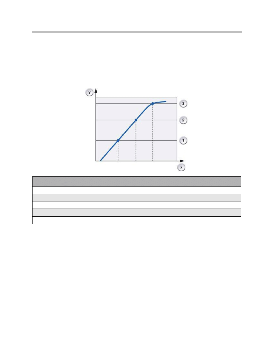
Target gear allocation dependent on accelerator pedal gradient
Target gear allocation dependent on the accelerator pedal gradient replaces the previous
target gear allocation system dependent on the accelerator pedal for the purpose of
shifting down while accelerating.
In the case of accelerator-dependent target gear allocation, based on the respective
downshift characteristic curves, the EGS determines whether a downshift is necessary
while accelerating.
The gearbox shifts down by one gear if the accelerator pedal is pressed and the first
downshift characteristic is reached within a certain time. If the accelerator pedal is
pressed further, the gearbox shifts down again to the second downshift characteristic and
again to response to the third downshift characteristic.
In the case of accelerator pedal gradient dependent target gear allocation, the EGS deter-
mines the target gear already at the first downshift characteristic.
The accelerator pedal gradient is used for this purpose. This is the angle the movement
of the accelerator pedal currently described or expressed more simply, the speed at
which the accelerator pedal is depressed.
24
E70 Transmissions
Index
Explanation
x
Time
y
Accelerator pedal position
1
1st downshift characteristic
2
2nd downshift characteristic
3
3rd downshift characteristic
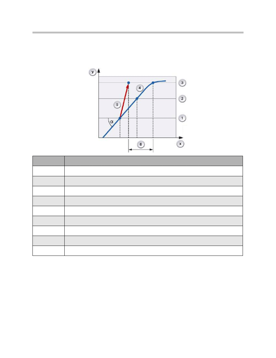
The target gear which is now determined in connection with the first downshift
characteristic is engaged by a multiple downshift function. This serves as a boost to
overall dynamics as the corresponding gear is engaged earlier and the interruption in
tractive power is minimized.
25
E70 Transmissions
Index
Explanation
x
Time
y
Accelerator pedal position
a
Accelerator pedal gradient
1
1st downshift characteristic
2
2nd downshift characteristic
3
3rd downshift characteristic
4
Accelerator pedal movement
5
Multiple downshift
6
Dynamics boost
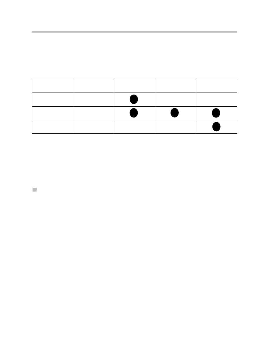
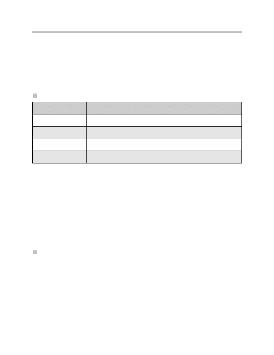
Shift Speed Characteristics
The transmission control now has three different shift speed levels known as quickshift 1,
2 and 3. The higher the level, the faster the gearshift. The respective shift speed level is
selected as a function of the selected drive program ("D", "S" or "M") and the accelerator
pedal gradient, i.e. as a function of the speed at which the pedal is depressed. The table
below shows an overview of the shift speed levels:
Torque Intervention
When shifting gear at low load or when coasting, the EGS sends a so-called torque pulse
to the engine management in order to achieve a torque intervention. This is negative
when upshifting so that the engine speed is reduced. When downshifting while coasting,
the torque intervention is positive in order to boost the engine speed. This torque inter-
vention facilitates smooth gearshifts without the torque converter having to intervene in
this task.
LIN-Bus Module
The EGS now contains a LIN-bus module for communication with the gear selector lever
(GWS).
Electronic-hydraulic Control
The electronic-hydraulic control installed in the GA6HP19/26TU has been optimized in
the following areas with regard to faster gearshift operations and higher efficiency.
• Torque converter control
• Cooling oil flow
• System pressure in "R"
• Clutch valves
• Electronic pressure control valves
The electronic-hydraulic control now has only two solenoid valves but seven electronic
pressure control valves.
26
E70 Transmissions
D
S
M
Quickshift 0
Comfortable
_
_
Quickshift 1
Comfortable and fast
Quickshift 2
Sport
_

Torque Converter Control
The torque converter control including the converter lockup clutch has undergone
distinct improvements with regard to the control capabilities under all conditions.
It is equipped with a new pressure regulator. Raised converter pressure (increased from
approximately 0.5 bar to 1 bar at the low end) ensures faster control of the converter
lockup clutch particularly at low temperatures.
The oil feed comes from the primary connection of the main pressure control valve, thus
improving control at low speeds. The converter lockup clutch is now engaged with a
backpressure in order to proportionate more effectively.
Variable Cooling Oil Flow
The flow of cooling oil is variable in order to reduce power losses. No cooling is required
for the clutch faces when the converter lockup clutch is engaged (closed). The flow of
cooling oil can be reduced in this state thus also reducing the pump power. The flow of
cooling oil is controlled by the main pressure and can vary between 10 l/min and 15 l/min.
27
E70 Transmissions

System Pressure in Reverse Gear
The system pressure that is applied in reverse gear has been increased from 15 bar to 16
bar. This change caters for the higher torque and the higher possible total weight. It
ensures that clutch slip is prevented even in extreme situations (e.g. uphill gradient with
trailer).
Clutch Valves
The clutch valves now exhibit a smaller control space. This facilitates a more sponta-
neous response as the time required until the clutch valve reacts to the control pressure
applied by the EDS is shorter. This results in distinctly shorter gearshift times.
Solenoid Valves (MV)
Two solenoid valves are mounted on the hydraulic selector unit. These valves are
designed as 3/2-way valves, i.e. valves with three connections and two switch positions.
The solenoid valves are controlled by the electronic transmission control (EGS) and
assume the "opened" or "closed" positions making it possible to switch over the
hydraulic valves.
The two solenoid valves are used for the electronically switched parking lock.
One solenoid valve controls the valve for the parking lock and the other solenoid valve
locks the cylinder for the parking lock.
Electronic Pressure Control Valves (EDS)
The electronic pressure control valves convert electrical current into a proportional
hydraulic pressure. They are driven by the EGS and operate the hydraulic valves belong-
ing to the shift elements.
The solenoid valve that the EDS (4) in the predecessor model assigned to the clutches
(D and E) depending on the gear to be shifted is no longer required. Instead another
electronic pressure control valve is used so that each clutch is now controlled by its own
electronic pressure control valve.
The pressure control valve 7 maintains a constant system pressure during the gearshift
operations, thus making shorter shift times possible.
The tasks of the electronic pressure control valves are listed in the following:
28
E70 Transmissions
EDS Valve
Influence on shift element
1
Drive clutch A
2
Converter lockup clutch
3
Drive clutch B
4
Drive clutch E
5
Drive clutch C
6
Drive clutch D
7
System pressure
Three different electronic pressure control valves (EDS) are now installed which are all
resistant to low temperatures. They enable stable presentation of the gearshift
requirements even at low temperatures and when the transmission fluid is cold:
29
E70 Transmissions
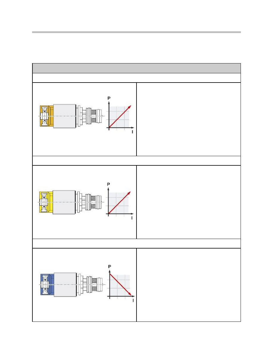
Electronic Pressure Control Valves (EDS)
EDS with rising characteristic
Electronic pressure control valves 1, 2:
Orange cap, rising characteristic
Technical data:
• Pressure range 0 to 4.7 bar
(0 mA = 0 bar, 700 mA = 4.7 bar)
• Supply voltage
12
V
• Resistance 5.05 Ohm (at 20 °C)
EDS with rising characteristic
Electronic pressure control valves 4, 5, 6:
Yellow cap, rising characteristic
Technical data:
• Pressure range 0 to 4.6 bar
(0 mA = 0 bar, 700 mA = 4.6 bar)
• Supply voltage
12
V
• Resistance 5.05 Ohm (at 20 °C)
EDS with falling characteristic
Electronic pressure control valves 3, 7:
Blue cap, rising characteristic
Technical data:
• Pressure range 0 to 4.6 bar
(700 mA = 0 bar, 0 mA = 4.6 bar)
• Supply voltage
12
V
• Resistance 5.05 Ohm (at 20 °C)

Gear Selector Lever
Emergency Release of Parking Lock
In the event of the system voltage failing, first release the electro-mechanical parking
brake (EMF) as the handle remains in the emergency release.
Do not remove the handle from the emergency release while the vehicle is being towed
as this will reengage the parking lock.
Releasing the parking lock with the emergency release generates a fault code entry in the
EGS: "Parking lock release error"
30
E70 Transmissions

31
E70 Transmissions
NOTES
PAGE
Document Outline
- Main Menu
- E70 Introduction
- E70 Glovebox
- E70 Powertrain
- E70 Gasoline Engines
- E70 Transmissions
- E70 Voltage Supply and Bus Systems
- E70 Car Access System 3
- E70 Energy Management
- E70 Chassis Dynamics
- E70 Lateral Dynamics Systems
- E70 Vertical Dynamics Systems
- E70 Longitudinal Dynamics Systems
- E70 Central Locking
- E70 Power Windows
- E70 Comfort Access
- E70 Wipe/Wash System
- E70 Panorama Glass Sunroof
- E70 Seats
- E70 Automatic Tailgate
- E70 Steering Column Switch Cluster
- E70 Exterior Lighting
- E70 Interior Lighting
- E70 Adaptive Headlight System
- E70 Park Distance Control
- E70 Rear-view Camera
- E70 Anti-Theft Alarm System
- E70 Outside Mirrors
- E70 Displays Indicators and Controls
- E70 Head-up Display
- E70 Information and Communication
- E70 Audio Systems
- E70 Rear Seat Entertainment
- E70 Climate Control Systems
- E70 Passive Safety Systems
Wyszukiwarka
Podobne podstrony:
Transmisja WAP
Sieci media transmisyjne
Media Transmisyjne
energoefekt artykul transmisja danych GPRS NiS[1]
Elektronik Inteligentny dom Transmisja Danych Siecia id 158
tariov,podstawy transmicji?nych,Przetwarzanie sygnałów mowy
tariov,podstawy transmicji?nych,Prezentacja informacji
02 Transmisjaid 3819 Nieznany
BMW X5 E70 2007pl
ABC Of Sexually Transmitted Infections
grzebyk, transmisja danych, pytania i odpowiedzi
A New Hybrid Transmission designed for FWD Sports Utility Vehicles
Asynchroniczna transmisja szeregowa
Technologia ciekłokrystaliczna pozwala na transmisję sygnału, materiały liceum i studia, Informatyka
więcej podobnych podstron