
1
A New Hybrid Transmission designed
for FWD Sports Utility Vehicles
Yota Mizuno, Masahiro Kojima, Hideto Watanabe, Hiroshi Hata
Tatsuhiko Mizutani,
Munehiro Kamiya, Keiji Takizawa
Toyota Motor Corp.
1 ABSTRACT
A new hybrid transmission (P310) has
been developed for FWD 3-liter engine
class sportsutility vehicles. The
development of this transmission has been
aimed at improving power performance and
fuel economy, achieving the world's top-
level weight reduction and compact size,
while maintaining high torque capacity. In
order to achieve these goals, the gear train
and motor have been newly designed, and
advanced technology has been applied.
Moreover, this hybrid transmission
achieves seamless acceleration and quiet
performance. This paper describes the
major features and performance of this
transmission in detail.
2 INTRODUCTION
Environmental and energy efforts, such as
reducing the volume of CO2 emissions and
improving the fuel consumption of
automobiles, are important activities for the
world. Under these circumstances, a hybrid
vehicle is able to achieve both high
acceleration performance and fuel
economy. In 1997, the first Prius was
introduced and recognized as the epoch-
making Eco friendly vehicle. In 2003, the
new Prius proposed a new hybrid drive
concept or Hybrid Synergy Drive, which
has better fun-to-drive features as well as
environmental performance.
This year,
we have developed a new hybrid
transmission for FWD 3-liter engine class
sports utility vehicles. This hybrid
transmission has been developed to
perform under the severe conditions
required in a SUV, while maintaining the
refinement deserving of a luxury vehicle.
3 DEVELOPMENT OBJECTIVES
The development objectives of this hybrid
transmission are as follows:
(1) Compact size
(2) Improved power performance
(3) Improved fuel economy
4 GENERAL CONSTRUCTION
This section describes the basic
construction of the new hybrid transmission
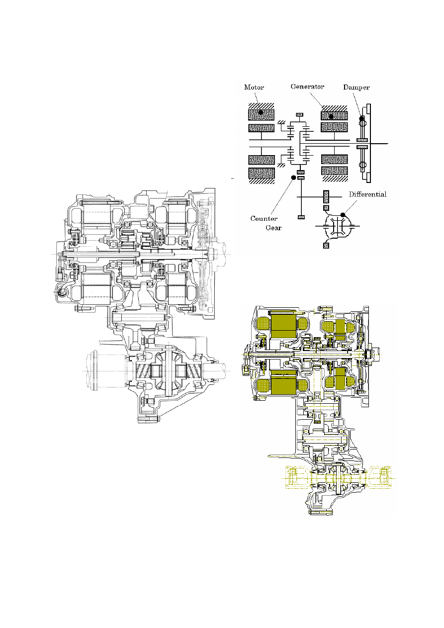
(P310). Figure 1 shows the cross section,
Figure 2 shows the gear train schematic,
and Table 1 shows the general
specifications. Basic construction of This
New hybrid transmission is quiet different
from that of Prius transmission (P112).
Figure 3 shows the cross section of Prius
transmission. The New hybrid transmission
has a newly adopted motor speed
reduction device and compound gear. A
newly adopted motor speed reduction
device allows motor torque to increase
2
without increasing motor size. A newly
adopted compound gear integrated of the
front planetary ring gear, rear planetary ring
gear, counter drive gear and parking gear.
A compound gear allows the gear train to
remain very compact by disusing a chain
and reduced from four axes to three axes
in comparison with Prius transmission
(P112), while maintaining high torque
capacity.
Figure 1: Cross Section of P310
Figure 2: Gear Train Schematic of P310
Figure 3: Cross section of P112
3
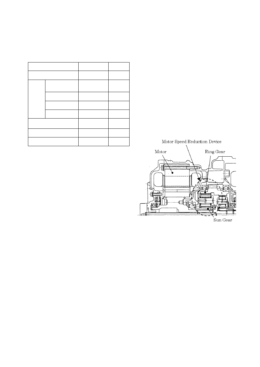
Table 1: Specifications of P310
Viewed from the right (engine side) of the
cross section, there are a damper with
torque limiter, a generator, two planetary
gear sets and a motor on the primary axis.
A front planetary gear (engine side) is
power split device. A rear planetary gear
(Motor side) is motor speed reduction
device. A Front planetary ring gear, a rear
planetary ring gear, a counter drive gear
and a parking gear are integrated into a
compound gear. On the secondary axis
there is a counter driven gear and a final
drive gear. A conventional differential axis
follows.
5 ACHIEVING COMPACT SIZE
The size of this hybrid transmission is
almost equal to that of the Prius
transmission (P112), though engine power
and motor power increase by more than 2
times. By adopting the motor speed
reduction device, compound gear and new
high power motor, an overall compact size
has been achieved.
5.1 Motor speed reduction device
Figure 4 shows the structure of the new
motor speed reduction device. The rear
planetary gear set operates as the motor
speed reduction device. Its sun gear is
linked to the motor and the carrier is fixed
at the case and the ring gear is linked to
the counter drive gear. The rear planetary
gear set is located inside the counter drive
gear. With the motor speed reduction
device, the rotational speed of the ring gear
is slower than that of the sun gear and the
torque of the ring gear is higher than that of
the sun gear.
Figure 4: Structure of Motor Speed
Reduction Device
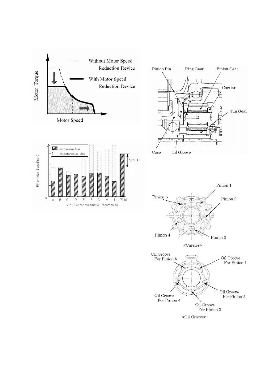
This hybrid transmission is designed so
that the motor reduction gear ratio is 2.478
and motor maximum speed is 12,400 RPM.
By the motor speed reduction device,
motor torque becomes 1 to 2.478. Since
motor size is proportional to motor torque,
a small torque but high speed motor can
decrease overall motor size (See Figure 5).
P310
P112
Max. Engine Torque
288Nm
115Nm
Type
Synchronous
AC motor
←
Max. Output
123kW
50kW
Max. Torque
333Nm
400Nm
Motor
Max. Speed
12400rpm
6000rpm
Motor reduction gear
ratio
2.478
-
Differential gear ratio
3.542
4.113
Weight (Including ATF)
125kg
109kg
4
Figure 5: Downsizing of Motor
Figure 6: Comparison of Pinion Maximum
Speed
With increasing of motor speed, rear
planetary pinion maximum speed is 50%
higher than conventional pinion maximum
speed (See Figure 6). High speed causes
flaking of pinion pin and pitting on gear face.
In order to improve this planetary durability,
the gear, carrier, and needle bearing
shapes were modified and the lubrication
was optimized (See Figure 7). A five-pinion
type gear set has reduced gear load on a
pinion in comparison with a four-pinion type
gear set. Cage and roller type bearings
were adopted in the pinion gear. Oil is
supplied to each bearing via an oil groove
(See Figure 8). Helix angle of pinion was
optimized in consideration of both durability
and gear noise.
Figure 7: Structure of Five-Pinion Type
Gear Set
Figure 8: Shape of Oil Groove
5
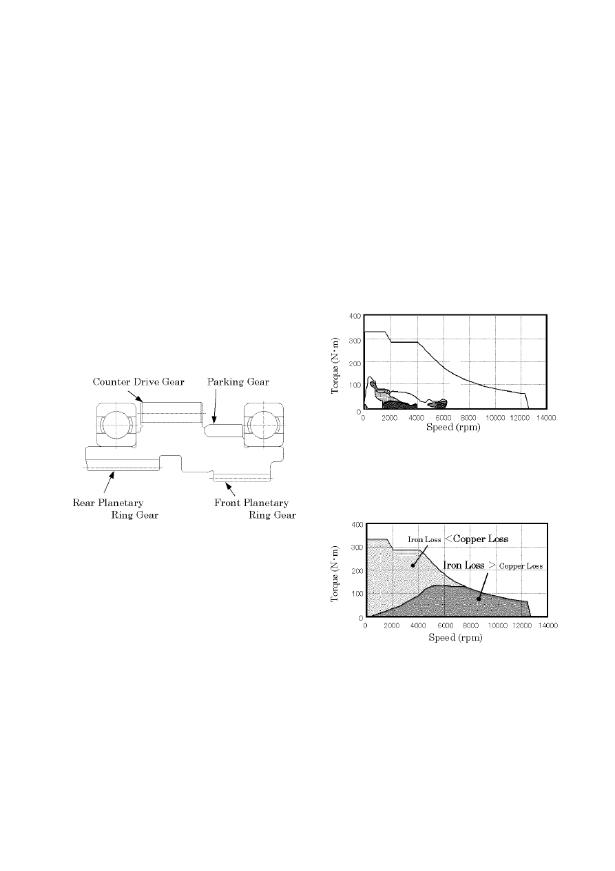
5.2 COMPOUND GEAR
Compound gear consists of the front
planetary ring gear, rear planetary ring gear,
counter drive gear and parking gear. By
integration of its 4 parts, the gear train
remained very compact. At the same time
by arranging large diameter bearings on
the outside of planetary gear sets, there is
no increase of length for its bearings. Since
the compound gear is a large diameter and
has a thin web, there is a fear of distortion
during quenching. By optimizing the
quenching and tempering treatment,
distortion during quenching was prevented.
Figure 9: Structure of Compound Gear
6 IMPROVEMENT OF POWER PER-
FORMANCE AND FUEL ECONOMY
The conventional traction drive motor was
thoroughly revised and has been
downsized while providing high power
performance and high efficiency. This
section describes the outline of the
technical items for the new downsized
motor adopted to P310.
6.1 MOTOR SPEED, INCREASING
Figure 10 shows the frequency map of the
traction drive motor in normal driving
conditions and its feature is high frequency
in low load area. The main motor loss is the
copper loss which occurs in the coil as
joule heat and the iron loss which occurs in
the motor core. Iron loss reduction is
important to improve fuel consumption in
normal driving as it mainly accounts for the
low load area (See Figure 11).
Figure 10: Frequency Map in Town Ride
Condition
Figure 11: Motor Loss Rate
The feature in P310 is the downsized motor
based on the adoption of the reduction
gear which has more than double the
6
reduction ratio compared with the
conventional type; however, this reduction
gear adoption requires more than double-
speed motor operation. To achieve the high
speed rotation, satisfying the mechanical
condition such as the strength towards
centrifugal force, and reducing the iron loss
to avoid the insufficient fuel consumption is
vital thought the iron loss increase is
proportional to the square of the motor
frequency.
Significant reduction of the iron loss has
been achieved in P310 development by the
design and material revision.
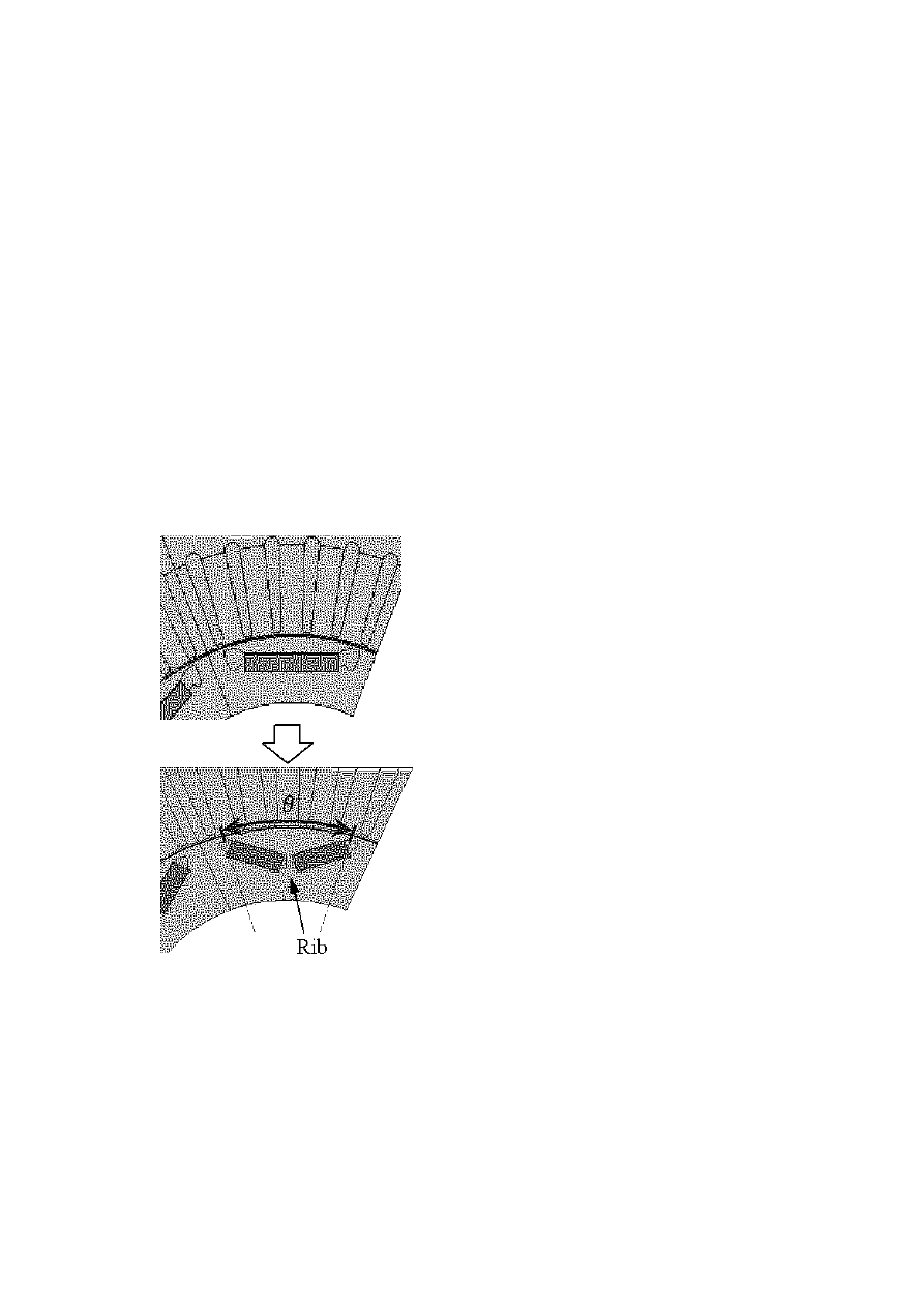
Figure 12: Rotor Permanent Magnet Layout
Regarding the design, reluctance torque
has been remarkably increased by the
layout change of the rotor permanent
magnet to V-formation (See Figure 12),
and it reduces the iron loss during the low
load application. The rib is newly adapted
to the center of the rotor to improve the
strength, and these modifications have
brought more than double-speed rotation
compared with the conventional motor.
Furthermore, the reduction of the harmonic
components in magnetic flux due to the
optimization of the open angle
θ in the
rotor magnet also contributes for the iron
loss reduction. These are optimized based
on the FEM including magnetic field and
strength analysis.
Regarding the material, new silicon steel
has been developed. It is thinner than the
0.35 mm silicon steel used in the Prius
transmission (P112) and enables to reduce
iron loss remarkably.
Other items related to the production
process such as stack method for the
silicon steel of stator were also revised and
as the whole result of those improvements,
iron loss has been remarkably reduced
from the conventional type (P112).
6.2 HIGHER VOLTAGE, DOWNSIZING
Compared to the P112 higher voltage and
reduced physical size of motor (coil-end)
were achieved in the P310. Following is a
description of the newly improved
technologies. Phase voltage of P310 has
increased from that of P112 by 30%. More
than 20% of the voltage is increased at its
peak while considering the surge caused
by a switching of an inverter. We have
designed insulating paper that would not
develop Partial Discharge Inception
Voltage (PDIV) at the peak. Also, the motor
is designed to keep the distribution voltage
low in a phase. We designed the new
motor considering the fact that phase
voltage and distribution voltage are
influenced by the length of cable
connecting an inverter and a motor and the
7
fact that PDIV is influenced by surrounding
conditions such as temperature and
humidity. Insulating material with superior
(Automatic Transmission Fluid) ATF
resistance and hydrolysis resistance was
adopted. Like P112, P310 is using ATF as
a motor coolant; therefore, ATF resistant
material is essential. Hydrolysis resistance
must be considered because ATF contains
a slight amount of moisture. In addition,
P310’s temperature range of operation is
higher than P112’s. ATF and hydrolysis
resistance in higher temperature is
required. Considering those points above
an insulator with a three-layered structure
was applied for P310.
P310 has achieved coil-end downsizing by
15% compared to P112. Considerations for
downsizing coil-end are formation of
insulating paper, choice of coiling material,
and production technology. A decrease of
dielectric strength voltage caused by
damages and pinholes on a coil as well as
partial discharge due to torn insulation
paper may occur during a formation of a
coil-end. Insulation quality during coil-end
forming is achieved by contriving the shape
of insulation paper, considering the
smoothness of the surface and the
hardness of a coil, and using a 0 type coil.
Moreover, cutting back the amount of coil
at the coil-end allowed us to accomplish
further downsizing.
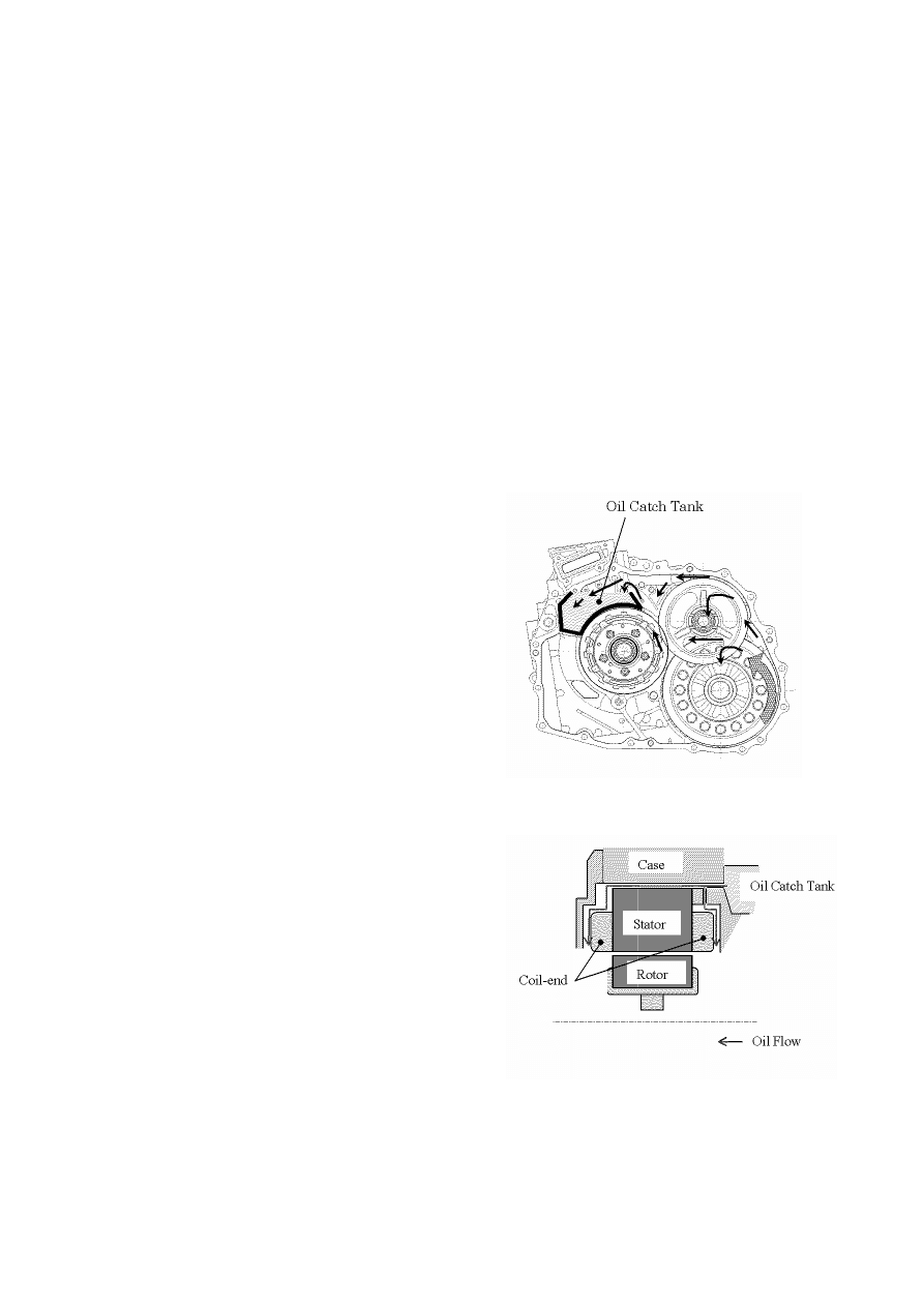
6.3 COOLING PERFORMANCE
As with P112, heat radiation for P310 is
conducted through the motor case. A
technology applied for P310 is a forced
ATF cooling which circulates ATF to the
stator in order to conduct heat away from
the stator to the motor case. The same air-
cooling system and water-cooling system
as in P112 are used to radiate heat from
the motor case. In order to improve the
cooling efficiency some vehicles use an oil
cooler to cool down ATF.
Heat radiation from the stator is conducted
by two paths; one from a metal contact
between the stator and the motor case and
another from the motor case in contact with
ATF. 30% to 50% of overall heat radiation
is caused by the metal contact. The rest of
the 50% to 70% of heat radiation is by
conduction between ATF and the motor
case. Cooling efficiency by ATF is much
greater in P310. Including the air-cooling,
we have achieved extensive upgrade of
overall cooling performance (See Figure
13,14).
Figure 13: Imaginary Diagram of Oil Flow
Figure 14: Imaginary Diagram of Motor
Generator Cooling

8
7 CONCLUSION
This new hybrid transmission (P310) has
been developed for FWD 3-liter engine
class sports utility vehicles. It is compact,
light weight and superior for power
performance and fuel economy. The
gearing, size reduction and enhanced
efficiency technologies are expected to
contribute greatly to enhancing the
performance of this hybrid transmission.
REFERENCES
1. S. Abe, S. Sasaki, H. Matsui, K. Kubo.
Development of Mass-produced Hybrid
System for Passenger Vehicles: 975,
pre-printed papers of the academic
lecture meeting, Society of Automotive
Engineers of Japan, Inc., Oct. 1997
2. S. Sasaki, T. Takaoka, H. Matsui, T.
Kotani. Toyota's Newly Developed
Electric-Gasoline Engine Hybrid Power
Train System: EVS-14, Dec. 1997
3. K. Tanoue, H. Miyazaki, Y. Kawabata,
T. Yamamoto, T. Hirose, G. Nakagawa.
Production and Technical Development
of EV and HV Units. Toyota Technical
Review Vol. 47, No. 2
4. M. Matsui, K. Kondo, R. Ibaraki, H. Ito.
Development of Trans-axle for Hybrid
Vehicles. Journal of Society of
Automotive Engineers of Japan, Vol.
52, Sept. 1998
5. K. Yoshimura, K. Ohshima, K. Kondo,
S. Ashida, H, Watanabe, M.Kojima.
Development of Trans-axle for Hybrid
Vehicles to Reduce Fuel Consumption.
Journal of Society of Automotive
Engineers of Japan, Vol. 58, Sept.
2004
Wyszukiwarka
Podobne podstrony:
New hybrid drying technologies for heat sensitive foodstuff (S K Chou and K J Chua)
Nonlinear Control of a Conrinuously Variable Transmission (CVT) for Hybrid Vehicle Powertrains
Caliber and?atures?tails for Seiko Sports Stopwatches
Design For Pcb Emi Emc Compliance
How to get the new iPod Touch(8GB) for nothing (easy to complete)
4 39 48 New Hot Work Steel for High Temp and High Stress Service Conditions
Dungeons and Dragons suplement New and Converted Races for D&D 3 5 Accessory
27 363 376 New Optimized Manufacturing Route for PM HSS
Defining the General Motors 2 Mode Hybrid Transmission
Learning Center Graphic Design for Everyone 05
Bearden Tech papers Vision 2000 The New Science Now Emerging for the New Millennium (www cheniere
Boost Converter Design For 20Kw Wind Turbine Generator
Graphic Design For The Web
Designed for Love Erin Dutton
więcej podobnych podstron