MANSON EP-925 MODIFICATIONS
EP-925 and PALSTAR PS-30M
On the Internet circulates an unclear copy of this supply's diagram and one is regularly
asked for a better drawing. As owner of this device I also wanted a good readable diagram.
So I draw a compact one using the Internet's example but it turned out the example had a
lot of errors.
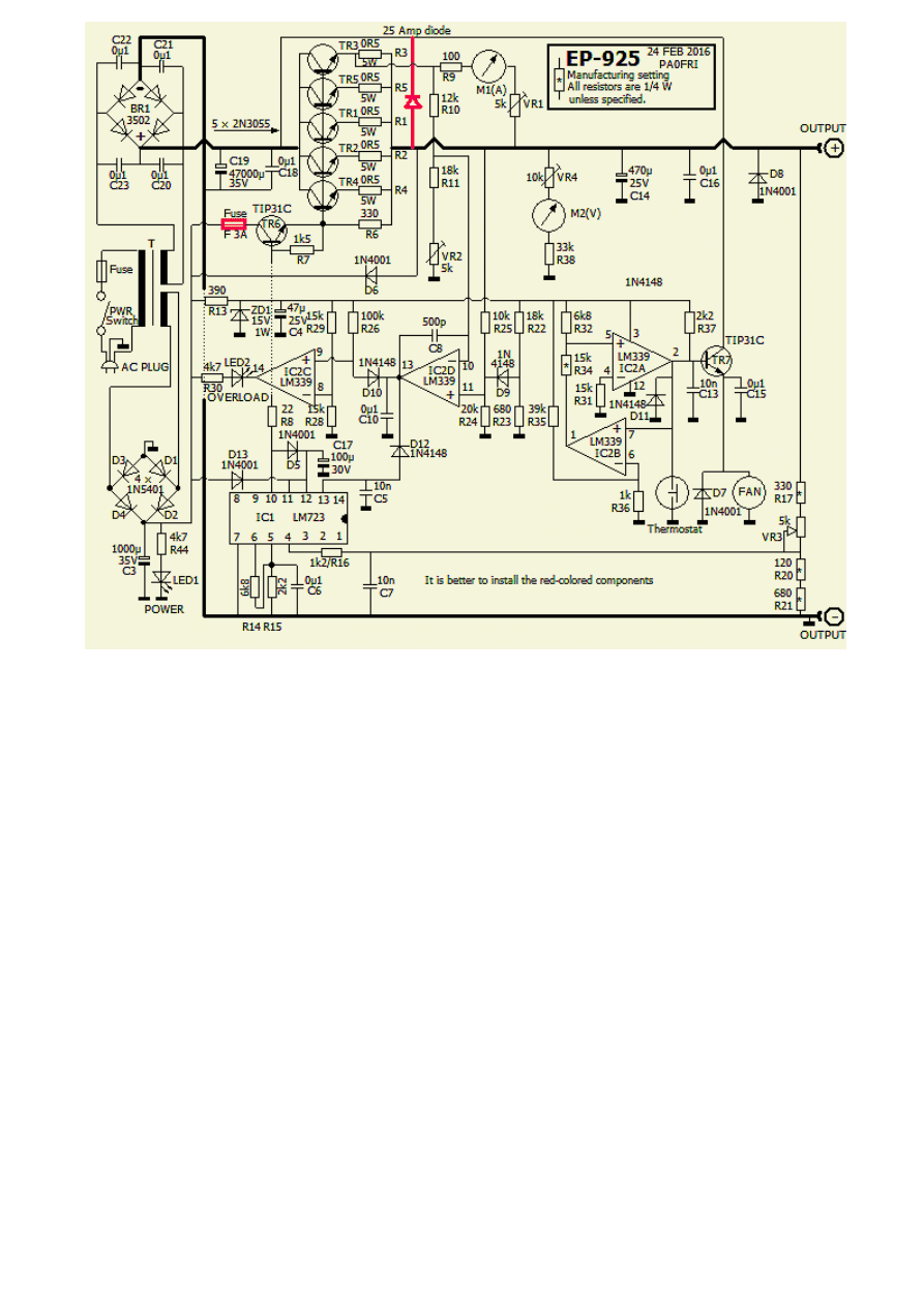
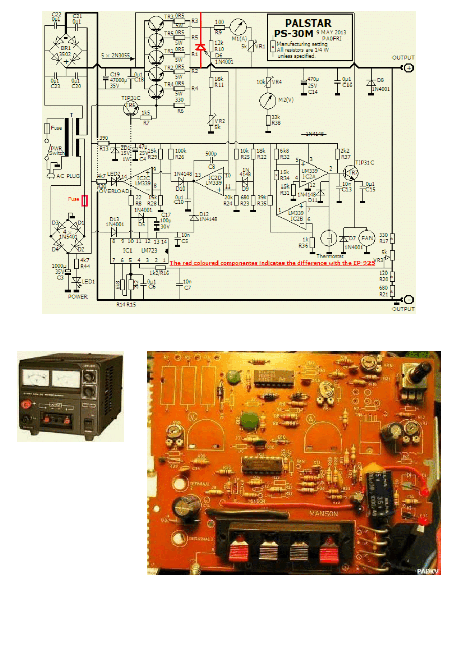
The Palstar below is almost similar except two red coloured components.
SHORTCOMINGS
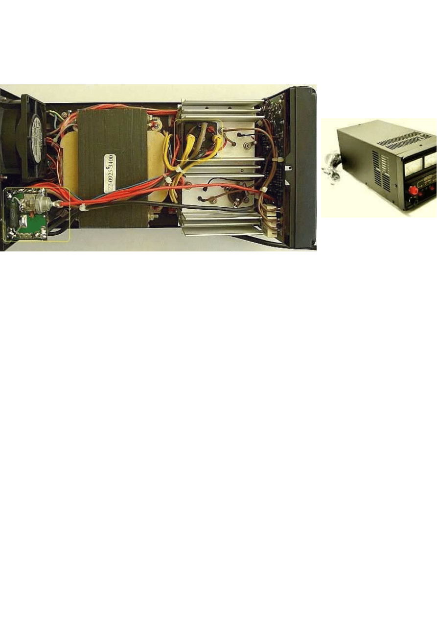
This power supply («fig) is
also for sale as EP-925 by
Conrad, Daiwa, ITM,
Manson, Palstar, Stabo,
Velleman, Voltcraft and
others. The unit is used in
many shacks but it has
some shortcomings, which
have resulted in failures.
Fortunately the device can be improved by some modifications.
OVERVOLTAGE
Remember that a surge protector is not present. If one transistors (TR1-TR5) blows, the
entire unregulated voltage (~ 24V) is connected to your set and it will usually not survive.
Such protection is still not in my EP-925 installed. You know the routine, the plan exists but
it need not be directly because I have other power supplies available. When use the EP-95
with a transceiver I always connect a small battery in parallel.
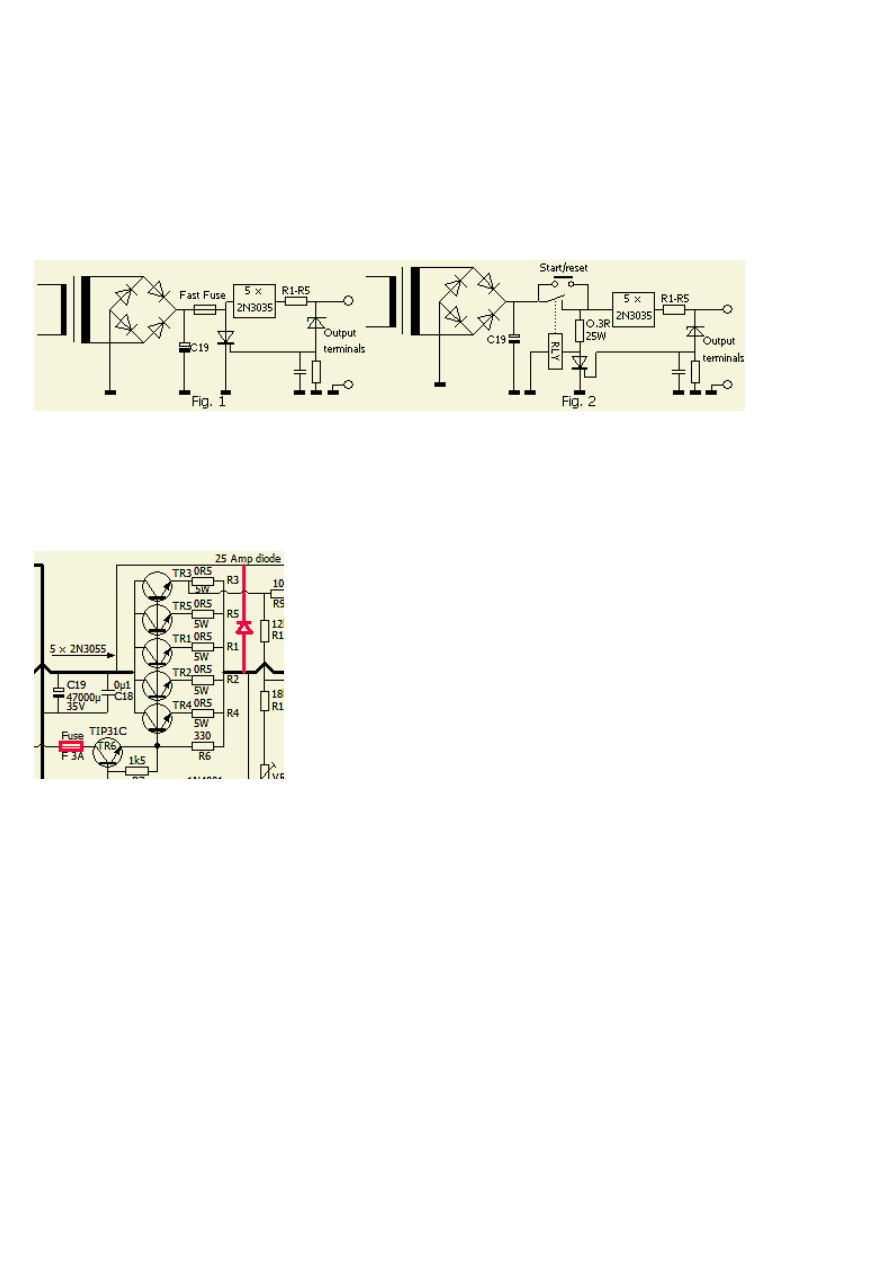
At right (fig.1») is the principle of a (15 V) overvoltage protection system. It is almost a
standard "brute force" circuit with a Zener diode driving a thyristor, which short-circuit the
overvoltage, a fuse blew and the set is no longer energised. Details of such security can be
found on the Internet.
A less crude system (fig.2) is very similar. After turning the
main switch and press the start/reset button, the relay connects and the power supply is on.
If the voltage at the terminals is too high, the thyristor is conducting and the voltage is
reduced to a safe value by the large current through the 0.3 Ohm resistor. Simultaneously,
the voltage across the relay is almost zero and disconnects the load. This is not a brute
force system and the thyristor is less affected.
G3MWO
wrote me: "With the crowbar applied, then there is a path from the auxillary
smaller power supply up through the TIP31C (TR6) and back through the combined
path through the base/collector junctions of all the 2N3055 transistors in parallel" (or
via the extra diode #PAØFRI)
In order to protect TR6 install a 3 Amp fast fuse in series with TR6's collector.
BRIDGE RECTIFIER
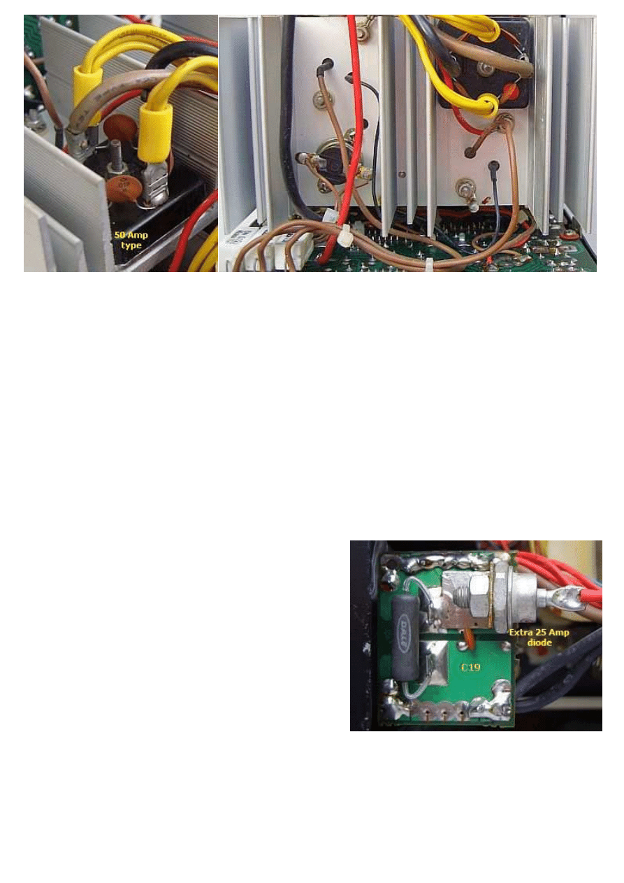
In my EP-925 only a 20 amperes bridge rectifier (DR1) was mounted, but the factory fitted
also a 25 Amp type.
Both rectifiers are only suitable for continuous use with about 12 A or 15 A and not to the
specifications of a 25 A continuous current or 30 A peak current. One has experienced that
a sustained large current will develop a fault.
I did not believe the factories specifications and therefore I tested the supply thoroughly.
The rectifier collapsed, but that was partly due to lack of cooling. The cause: the mounting
screw and nut were lose and there was no thermal paste applied between bridge rectifier
and heat sink. It is advisable to check all the fixing and thermal paste because my
transistors were providing with almost nil paste. After a 50 A rectifier bridge was installed
the power supply specifications were right and the unit has not failed since 1994.
SERIE TRANSISTOR
During the mentioned test a 2N3055-power
transistor had gone short circuit also by lose fixing
and nil paste. Again, check your power supply for
essential fixings and sufficient thermal paste.
VOLTAGE REMAINS
When the power is switched off, the voltage
remains for some time. For a faster discharge a
load resistor (fig») was installed parallel to the
unregulated voltage across capacitor (C19).
EXTRA DIODE
If the supply is used for battery charging it may happen that the power is switched off
before the battery is removed or the battery is connected before the unit is on. Temporarily
components can have a reverse polarity and failure. A large diode (fig») mounted from the
positive terminal to the plus pole of C19 can avoid this.
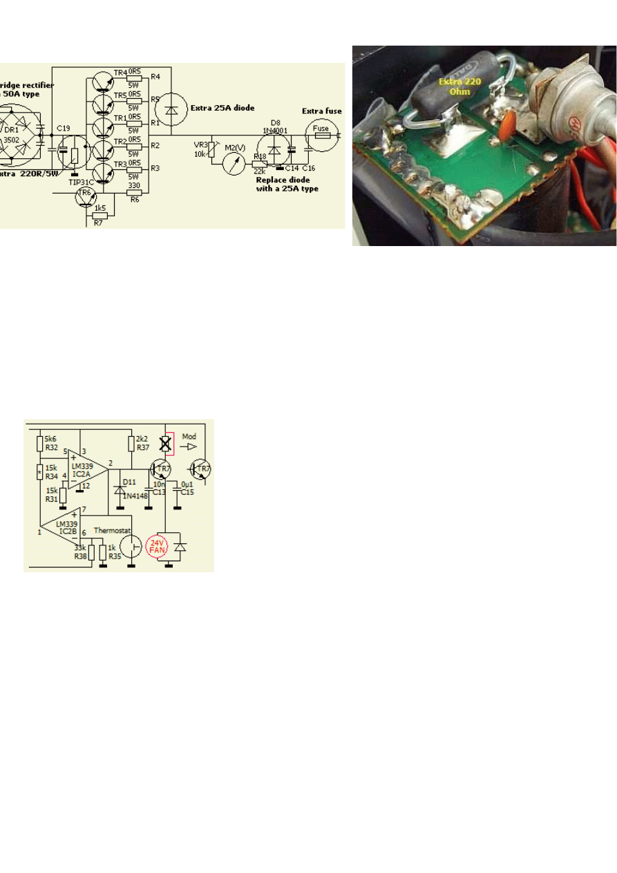
DIODE EN EXTRA FUSE
If accidentally the poles of a battery are reversed, diode D8 (1N4001) conducts and not
survives. One can installed the known reverse protection circuit by replacing a stronger
diode type (> 20A) and an additional output (25A) fuse. In case of wrong connection the
diode conducts and the fuse blow.
OTHER FAN
The original 12 V fan was too noisy and did not sufficiently cooled at maximum load. That is
mainly because the insufficient mounting of all components. One resistor («fig) was
removed or short circuit and a powerful fan type was replaced: a 24 V PAPST Multifan 8314.
Now the airflow is sufficient with less noise.
The resistor in TR7's collector is not always installed in this type of power supply!
G3MWO
cured the overheating by running the fan slowly all the time - but also added
a series of 6 mm holes in the bottom of the case just in front of the heatsinks for air
flow through the lower heatsinks.
PAØKV's MODIFICATIONS
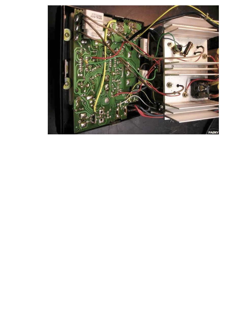
PAØKV has
designed some
interesting
changes. He
was not
satisfied with
the voltage
stabilization at
maximum load.
In examining
the cause he
discovered a
number of
weaknesses of
the design. In
his enthusiasm
to proceed, he
thought the
changes might be too far. However the result was a safe, quiet and stable 13.8 V supply for
its transceiver. His findings are given below
STABILITY
The LM723 (IC1) voltage regulator is not working properly despite feeding with a separate
winding on the transformer. The output voltage varies considerably due to the heavy load of
the system to the other secondary winding and probably by thin wire on the primary
windings.
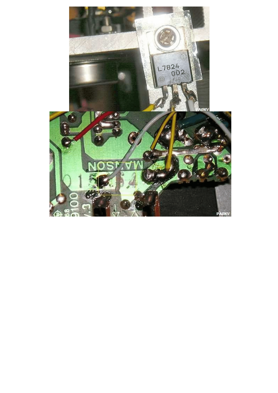
To improve, he replaced D13 (1N4001) with an additional 24 V stabilizer (7824) mounted on
the heat sink and a track was interrupted. Since C17 was not installed in his EP-925 he
mounted a 100 nF capacitor.
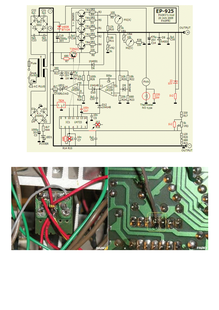
The changes are marked in red. The circuit for the fan is simplified.
The circuit of the LM723 (IC1) voltage regulator could be improved. NPN TR6 (TIP31C) was
replaced by a PNP transistor TIP42C with increased HFE that contribute to the stabilization.
A track (fig») below IC1 was cutted. Further pin 12 (V
+
) was connected to 7824, pin 11 (Vc)
to the base of TIP42C, pin 10 (Vout) to the emitter of TIP42C. Resistor R7 (1.8 k) replaced
by 680 ohms and R8 (22 Ohm) and D5 (1N4001) removed.
The inputs of the LM723 were designed for lower voltages (up to 9 V) to the outputs. He
chose for 13.8 V, R14 was reduced to 680 ohms. He decreased the maximum voltage across
VR3 (5 kOhm) to 14 V with a 1.2 kOhm resistor in parallel of VR3.
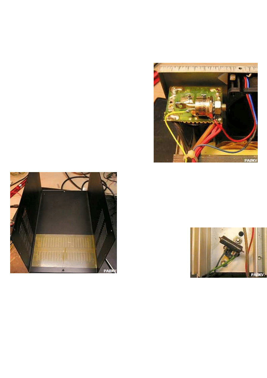
SAFE OVERVOLTAGE
For maximum 14 V voltage at the output terminal
he applied a 16 V overvoltage protection. A thyristor
(BTV24/1400R) was mounted in parallel with (fig»)
an installed bridge rectifier (50 A/120 V). A zener
diode (ZD2) and resistor (100 ohms) across the
output trigger the action.
FAN
In his opinion the circuit for the fan is overly
complicated: a thermostat, two opamps and a
transistor to switch a fan! I am agreeing! The
reason is probably the use of an NC (Normal
Closed) thermostat.
The fan was replaced by a PAPST 844414NG and
mounted to suck the hot air out of the casing.
Thus reduces noise considerably. To increase the
airflow through the side slits, he sealed the air
gaps («fig) of the lid with tape.
The original fan's supply
system was
superfluously because
the thermostat was
replaced by an N-type
(Normal Open) in series with the fan. With a (fig») 220 Ohm/5 W
resistor parallel to the thermostat the fan runs quietly at half speed and constantly cooled
the heat sinks. It's never happened that the fan was running at full capacity.
LY3BG MODIFICATIONS
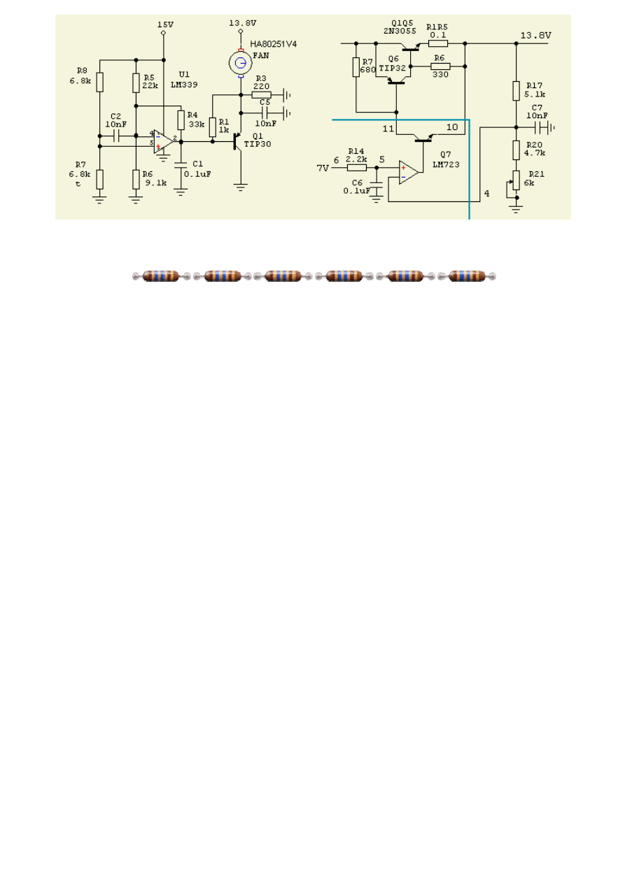
Left: R7 (6k8) is a thermistor, FAN = silent fan; Right: R1-R5 = 0.1 Ohm.
Wyszukiwarka
Podobne podstrony:
Convert Computer ATX Power Supply to Lab Power Supply
Jvc Power Supply Description And Trouble Shooting Procedure
Battery Inverter For Modularly Structured Pv Power Supply Systems
0 50V 2A LM10C, 0 50V 2A Bench power supply circuit diagrams, schematics, electronic projects
(Wydruk – ATX Switching Power Supply 13,8 V Proste zmiany w celu zwiększenia napięcia wyjściowego Ja
Alarm Power Supply L78Sxx id 61 Nieznany (2)
3 2 Lab Install Power Supply
HY3010 power supply, Elektronika, Zasilacze, Zasilacz HY3010, Zasilacz HY3010, HY3010 ,INSTRUKCJA
Lekturki Power Supply Unit Lekturka
How to Modify an ATX Computer Power Supply
Adaptive fuzzy control for uninterruptible power supply with three phase PWM inverter
Control and Power Supply for Resistance Spot Welding (RSW)
Performance Improvements in an arc welding power supply based on resonant inverters (1)
Convert Computer ATX Power Supply to Lab Power Supply
(ebook free energy) 50000 vdc power supply
(ebook electronics) Schematics Power Regulated Power Supply for CB & Ham Radio
Sovereign XS Power Supply Schematic
03a E46 Power Supply and Bus Systems
Adaptive fuzzy control for uninterruptible power supply with three phase PWM inverter
więcej podobnych podstron