
Initial Print Date: 03/05
Table of Contents
Subject
Page
xDrive . . . . . . . . . . . . . . . . . . . . . . . . . . . . . . . . . . . . . . . . . . . . . . . . . . . . . . . . .5
DSC8+ . . . . . . . . . . . . . . . . . . . . . . . . . . . . . . . . . . . . . . . . . . . . . . . . . . . . . . . .5
System Circuit Diagram . . . . . . . . . . . . . . . . . . . . . . . . . . . . . . . . . . . . . . . . .6
System Components . . . . . . . . . . . . . . . . . . . . . . . . . . . . . . . . . . . . . . . . . . .9
ATC 300 Transfer Case . . . . . . . . . . . . . . . . . . . . . . . . . . . . . . . . . . . . . .10
Adjusting Levers . . . . . . . . . . . . . . . . . . . . . . . . . . . . . . . . . . . . . . . . . . . .12
Servomotor with Motor Position Sensor . . . . . . . . . . . . . . . . . . . . . . .12
Coding Resistor . . . . . . . . . . . . . . . . . . . . . . . . . . . . . . . . . . . . . . . . . . . .13
Transfer Case Electronic Control Unit . . . . . . . . . . . . . . . . . . . . . . . . .13
DSC8+ Control Unit . . . . . . . . . . . . . . . . . . . . . . . . . . . . . . . . . . . . . . . . .14
Wheel Speed Sensor . . . . . . . . . . . . . . . . . . . . . . . . . . . . . . . . . . . . . . . .14
DSC Sensor . . . . . . . . . . . . . . . . . . . . . . . . . . . . . . . . . . . . . . . . . . . . . . . .15
Bus Overview . . . . . . . . . . . . . . . . . . . . . . . . . . . . . . . . . . . . . . . . . . . . . .15
Power Flow . . . . . . . . . . . . . . . . . . . . . . . . . . . . . . . . . . . . . . . . . . . . . . . .16
DSC/DSC8+ Control Unit . . . . . . . . . . . . . . . . . . . . . . . . . . . . . . . . . . . .17
Transfer Case (VGSG) Control Unit . . . . . . . . . . . . . . . . . . . . . . . . . . . .17
Transfer Case Control . . . . . . . . . . . . . . . . . . . . . . . . . . . . . . . . . . . . . . .18
Tire Tolerance Logic . . . . . . . . . . . . . . . . . . . . . . . . . . . . . . . . . . . . . .19
Traction Control / Driving Dynamics Control . . . . . . . . . . . . . . . . .22
Limp Home Operation . . . . . . . . . . . . . . . . . . . . . . . . . . . . . . . . . . . .23
Dynamic Stability Control . . . . . . . . . . . . . . . . . . . . . . . . . . . . . . . . . . . .24
ASC-X / ADB-X . . . . . . . . . . . . . . . . . . . . . . . . . . . . . . . . . . . . . . . . . .24
Hill Decent Control (HDC) . . . . . . . . . . . . . . . . . . . . . . . . . . . . . . . . .25
Dry Braking . . . . . . . . . . . . . . . . . . . . . . . . . . . . . . . . . . . . . . . . . . . . .26
Brake Standby . . . . . . . . . . . . . . . . . . . . . . . . . . . . . . . . . . . . . . . . . . .27
Automatic Soft Stop . . . . . . . . . . . . . . . . . . . . . . . . . . . . . . . . . . . . .28
Fading Compensation . . . . . . . . . . . . . . . . . . . . . . . . . . . . . . . . . . . .29
Drive-off Assistant . . . . . . . . . . . . . . . . . . . . . . . . . . . . . . . . . . . . . . .30
Transfer Case and Clutch . . . . . . . . . . . . . . . . . . . . . . . . . . . . . . . . .32
E60/E61 xDrive with DSC8+
Revision Date: 04/05


3
E60/E61 xDrive with DSC8+
E60/E61 xDrive with DSC8+
Model: 525xi, 530xi, 530xiT
Production: From April 2005
After completion of this module you will be able to:
• Familiarize yourself with DSC8+ features
• Explain the xDrive mechanical operation
• Describe the xDrive power flow

xDrive with DSC8+
From 04/2005, the BMW 5 Series wagon and sedan (optional) will have all wheel drive
capability utilizing the tried and tested all-wheel drive system xDrive of the X3 and X5.
The innovative all-wheel xDrive is a system for controlling and regulating the “infinitely”
variable drive torque distribution over the front and rear axle. The xDrive uses the system
functions of the DSC to positively influence the vehicle handling by specifically distribut-
ing the power in the event of understeer or oversteer.
With the controlled multi-disc clutch in connection with the xDrive it is now possible to
resolve the conflict between traction and vehicle handling.
This is been achieved in that the xDrive does not predefine the torque distribution by a
fixed transmission ratio as is the case with the previous systems. Instead, distribution of
the drive torque is dependent on the clutch lockup torque of the controlled multi-disc
clutch in the transfer case and on the transmitted torque at the front and rear axle.
Driver Benefits
In addition to the previous functions, a series of additional safety and comfort functions
will now be available to the driver with the introduction of the DSC8+ in the E60/E61.
The expanded DSC8+ functions include:
• Dry braking
• Brake standby
• Automatic soft-stop
• Fading warning and assistance
• Drive-off assistant
• Hill descent control HDC
Besides the outstanding chassis characteristics of the BMW 5 Series, the all wheel drive
system offers traction advantages not only on snow and ice but also on unsurfaced
roads.
Note: Because many system components and functions and are shared
between the xDrive and DSC8+ system, they will be discussed
together in this section.
4
E60/E61 xDrive with DSC8+

xDrive
The innovative xDrive four-wheel drive is a system that controls and regulates the distrib-
ution of driving torque to the front and rear axles. The measured variables of DSC are
used by xDrive but are also influenced by modified handling performance.
The multi-disc clutch is the heart of the xDrive. By using the controlled multi-disc clutch,
it is possible to resolve the conflict between traction and handling performance.
This is achieved through the fact that torque distribution is not determined by a fixed gear
ratio in the xDrive as was the case in the previous systems. Instead, the distribution of dri-
ving torque is dependent on the locking torque of the controlled multi-disc clutch in the
transfer case and on the transferable torque to the front and rear axles.
DSC8+
The DSC8+ system adds features to the DSC8 system already in use in the E60 sedan
and combines features used in other DSC systems (E53/83). Due to the mechanical
composition of the xDrive system, the programming for DSC regulation has also been
changed.
Present DSC8 functions:
• ABS Anti-lock Braking System
•
ASC Automatic Stability Control
• ADB Automatic Differential Brake
•
DSC Dynamic Stability Control
• EBV Electronic Braking Force Distribution
•
DBC Dynamic Brake Control
• CBC Cornering Brake Control
•
MSR Engine Drag Torque Control
Present DSC functions:
• TCC Transfer Case Control
(control of multi-disc clutch in transfer case)
• ASC-X Automatic Stability Control X
(special function for all-wheel drive vehicles)
• ADB-X Automatic Differential Brake X
(special function for all-wheel drive vehicles)
• HDC Hill Decent Control
New DSC/DSC8+ functions
• Dry braking
•
Brake standby
• Automatic soft stop
•
Fading assistance
• Drive-off assistant
•
Trailer stabilization control
• Hill descent control HDC
5
E60/E61 xDrive with DSC8+
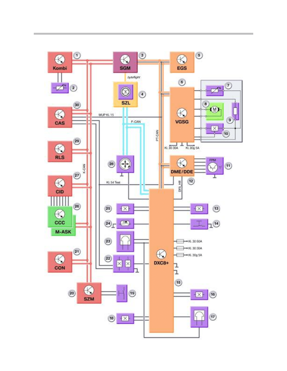
System Circuit Diagram
6
E60/E61 xDrive with DSC8+

System Circuit Diagram Legend
7
E60/E61 xDrive with DSC8+
Index
Explanation
1
Instrument cluster
2
Outside temperature sensor
3
Safety and gateway module (SGM)
4
Steering column switch cluster (SZL)
with HDC button
5
Electronic transmission control module (EGS)
6
Transfer case control unit (VGSG)
7
Temperature sensor
8
Electronic motor, actuator drive
9
Coding resistor
10
Motor position sensor
11
Accelerator pedal module (FPM) - (not for US)
12
Digital motor electronics (DME) control unit
13
Wheel speed sensor, front right
14
Handbrake switch
15
Dynamic traction control (DSC8+)
16
Wheel speed sensor, rear right
17
Brake wear sensor, rear right
18
Wheel speed sensor, rear left
19
DSC button
20
Center console switching center (SZM)
21
Controller (CON)
22
Brake light switch (BLS)
23
Brake wear sensor, front left
24
Brake fluid level sensor
25
Wheel speed sensor, front left
26
CCC or M-ASK
27
Central information display
28
Yaw rate/longitudinal/transverse acceleration sensor (Y-sensor-2)
29
Rain light sensor (RLS)
30
Car Access System (CAS)

8
E60/E61 xDrive with DSC8+
NOTES
PAGE
9
E60/E61 xDrive with DSC8+
System Components
The xDrive/DSC8+ system is composed of the following major components:
• ATC 300 transfer case
• Adjusting levers
• Servomotor with motor position and temperature sensor
• Coding/classification resistor
• Transfer case control unit
• DSC8+ control unit
• Wheel speed sensor
• DSC sensor (Y-sensor 2)
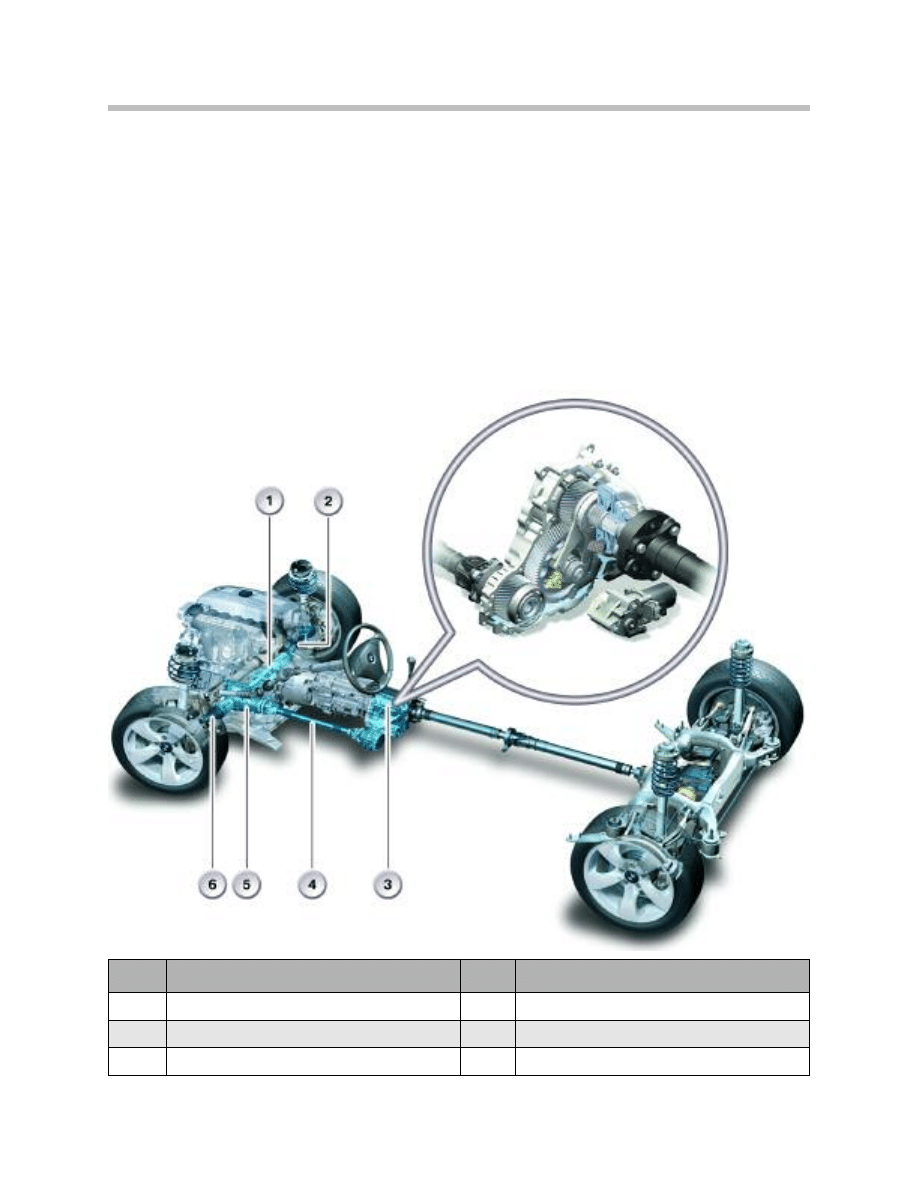
Index
Explanation
Index
Explanation
1
Oil Pan lead through
4
Propeller shaft to front axle
2
Right drive shaft, front
5
Front axle differential
3
Transfer case
6
Left drive shaft, front
10
E60/E61 xDrive with DSC8+
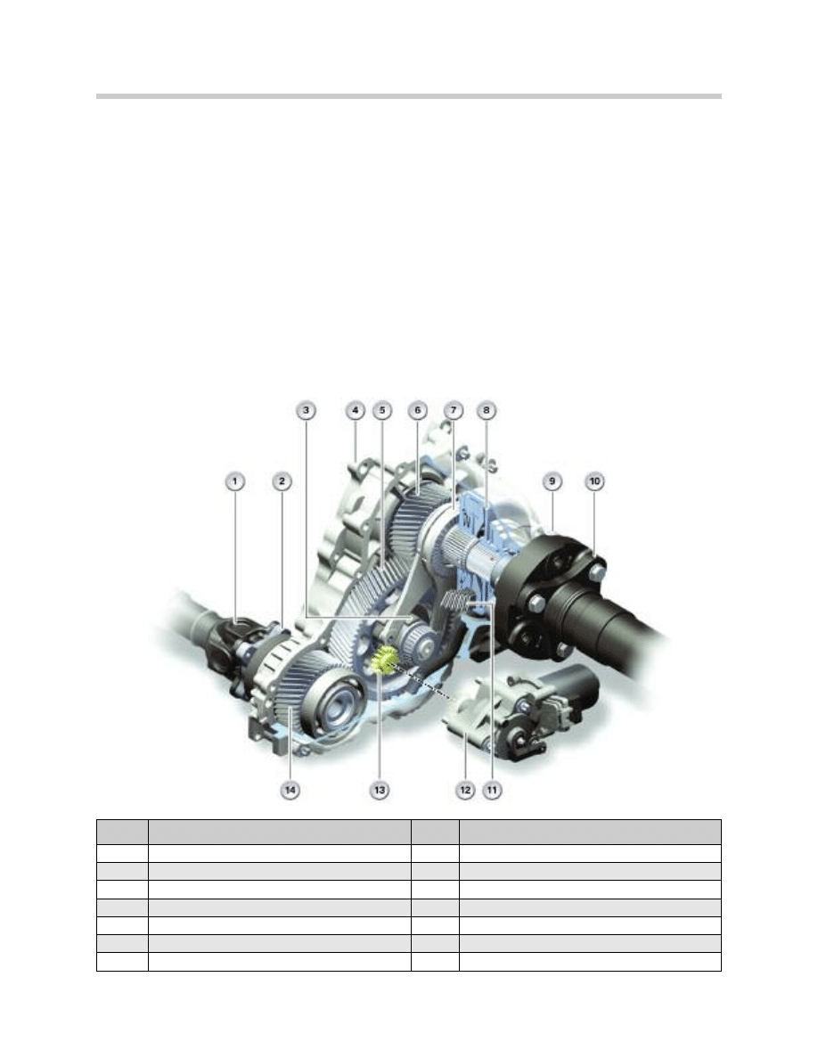
ATC 300 Transfer Case
The transfer case ATC 300 (Active Torque Control) is used on the E60/E61.
In view of the restricted package space of the transmission tunnel in the BMW 5 Series, it
was not possible to adopt the transfer case from the BMW X3 (ACT400) with the same
torque rating.
On the BMW 5 Series it was not possible to drive the forward power flow diagonally as is
the case on the X3 with a chain, but rather it is necessary to divert it L-shaped with the
aid of spur gears (pinions), resulting in a modified design of the transfer case.
The actuator drive and the actuation of the control lever were also modified. The clutch
package remains unchanged. The forward connection is provided by a bolted on drive
shaft.
The flange of the ATC transfer case is the same for automatic and manual transmissions.
Index
Explanation
Index
Explanation
1
Propeller shaft to front axle
8
Clutch housing
2
Drive flange to front axle
9
Output flange to rear axle
3
Control cam
10
Propeller shaft to rear axle
4
Transfer case
11
Disc package
5
Idler gear
12
Actuator drive
6
Drive gear
13
Drive pinion
7
Control lever
14
Output gear
ATC 300 Transfer Case
11
E60/E61 xDrive with DSC8+
The ATC 300 is installed in the E61 and E60 all wheel drive models. The ATC 400 is
installed in the E83 and the ATC 500 in the E53 MU.
The ATC 300 differs from the other transfer cases because it is gear driven not chain
driven. The basic functions and operations remain unchanged.
The difference between the transfer cases are:
• ATC 400 & 500 are chain driven vs. ATC 300 which is gear driven
• ATC 300 & 400 uses a four bolt flange to connect to the front propeller shaft vs.
ATC 500 which uses a splined connection
• ATC 500 utilizes one more disc in the multi-disc clutch than the ATC 300 & 400
• ATC 500 has 19mm greater length between the input shaft and the output shaft to
the front axle than the ATC 400. (the ATC 300 uses gears not a chain)
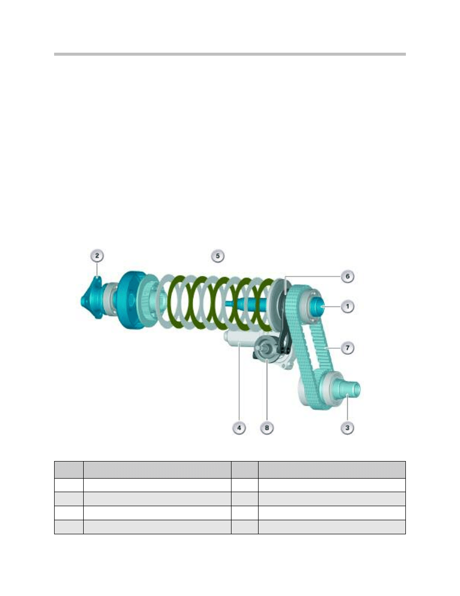
Index
Explanation
Index
Explanation
1
Input from manual / automatic transmission
5
Clutch discs
2
Output to rear axle prop. shaft
6
Adjusting levers with ball ramp
3
Output to front axle prop. shaft
7
Chain
4
Servomotor
8
Disc cam
ATC 500 Transfer Case

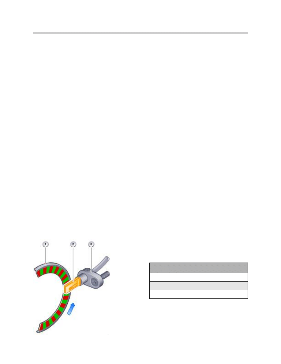
Adjusting Levers
The actuator drive unit operates such that the drive pinion rotates and engages via the
gearing in the control cam. In turn, the control cam is rotated and the control lever
pressed apart.
The rotary motion is converted into an axial force by the ball ramps in the control lever.
The axial force that compresses the disc package in the multi-disc clutch is proportional
to the transmitted torque of the multi-disc clutch.
The position of the control lever is infinitely variable and allows exact regulation of the
control cam by the actuator drive unit.
Servomotor with Motor Position Sensor
The actuator drive unit is a DC motor with worm drive. It also features a Hall sensor that
serves the purpose of determining the position and the adjustment speed of the motor
shaft. The position of the motor shaft determines the closing rate of the multi-disc clutch.
There is also a temperature sensor installed in the motor that signals the temperature to
the transfer case control unit (VGSG). A temperature model is calculated in the VGSG for
the purpose of protecting the motor from overload. For this purpose, the maximum clos-
ing rate is reduced in various stages.
If these measures are not sufficient to protect the motor from overload, the control is
interrupted and the clutch completely opened so that only rear axle drive is now possible.
12
E60/E61 xDrive with DSC8+
Index
Explanation
1
Magnetic ring
2
Motor position sensor (Hall sensor)

Coding Resistor
Because of mechanical tolerances in production, the characteristic curve of the multi-disc
clutch locking torque varies slightly.
Once the actual locking torque has been measured on the clutch test bench, a resistor is
attached to the servomotor; the resistor's value is a reference to the locking torque char-
acteristic.
Each time the engine is started, the transfer case control unit measures the resistance
value once and the optimum program map for the transfer case fitted is selected.
Transfer Case Electronic Control Unit
The transfer case control unit (VGSG) is on CAN-bus.
Depending on the vehicle, the module is installed in the following location:
• E60/61 - under the rug foward of the passenger’s front seat
• E83 (X3) - under the rear floor panel of the cargo compartment trim
• E53 (X5) - under the rear bench on the left side
13
E60/E61 xDrive with DSC8+
Index
Explanation
1
Drive pinion
2
Electric motor
3
Coding resistor
4
Actuator drive housing
Index
Explanation
1
Kick guard
2
Transfer case control unit
3
Connector
DSC8+ Control Unit
The DSC8+ control unit is installed in the engine compartment essentially consists of
three components:
• Add-on control unit
• Valve block with integrated pressure sensors
• Pump motor
The newly developed changeover valves permit even more exact control in the low pres-
sure range, resulting in the following advantages:
• Reduction of control noise
• Improvement in control quality and control comfort
• Improvement in automatic brake intervention by the active/dynamic cruise control
ACC/DCC
• Improvement in the control accuracy of the HDC function
• Realization of additional brake functions
Wheel Speed Sensor
Active wheel speed sensors with an integrated evaluator circuit are used together with
the xDrive.
The active wheel speed sensors require a power supply for their operation. The output
signal is sent as a data protocol based on the pulse-width modulation method (PWM).
The PWM signal is used for the purpose of determining the road speed. The pulse width
contains additional information relating to the direction of rotation, standstill detection,
installation position detection, and air gap reserve to the sensor ring. (example : sends
one pulse every 0.75 s when the wheel is stationary)
The direction of rotation is determined by the internal signal offset of three correspond-
ingly arranged Hall-effect elements in the sensor.
14
E60/E61 xDrive with DSC8+
Index
Explanation
1
Sensor ring
2
Sensor-IC with Hall sensor
3
Sensor housing
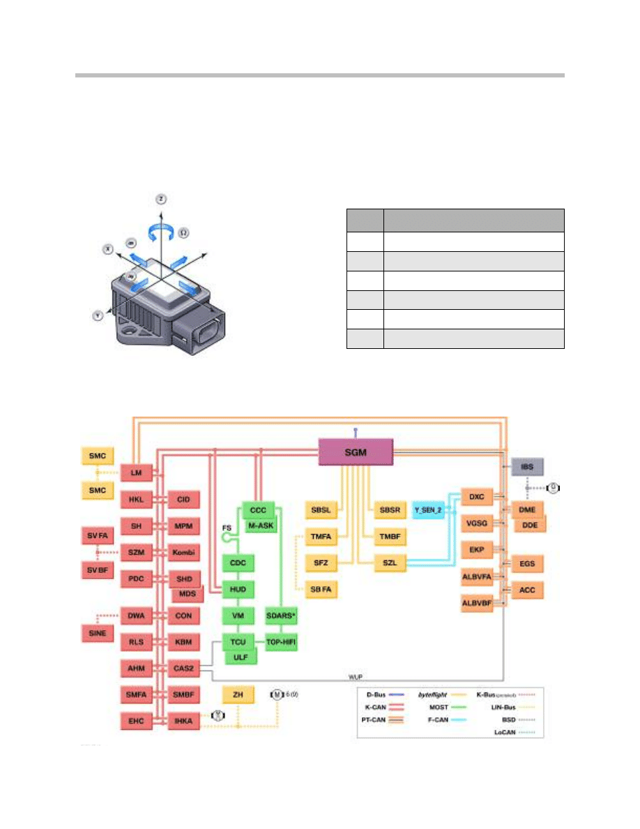
DSC Sensor
The DSC sensor (Y-sensor 2) is installed under the front passenger's seat next to the
transmission tunnel.
In addition to the previous yaw rate and transverse acceleration sensor, the DSC sensor
also contains an additional longitudinal acceleration sensor for the drive-off assistant
function.
Bus Overview
The transfer case control unit (VGSG) is on the PT-CAN. VGSG shares information with
DSC for overall xDrive control and has diagnostic communication.
15
E60/E61 xDrive with DSC8+
Bus Topology Chart of E61 Sports Wagon (530xiT)
Index
Explanation
X
Longitudinal axis
Y
Transversal axis
Z
Vertical axis
ax
Longitudinal acceleration
ay
Lateral acceleration
W
Yaw rate

Principles of Operation
Power Flow
When the multi-disc clutch in the transfer case is disengaged, no driving torque is trans-
mitted to the front axle. All of the driving torque is then distributed to the rear axle. This is
because the input shaft (1) is splined providing a permanent connection to the rear axle
propeller shaft output flange (2). The multi-disc clutch couples the rear axle propeller
shaft output flange to the front propeller shaft output (3).
The driving torque on the front axle is increased or decreased by regulating the locking
pressure of the multi-disc clutch, providing a stepless coupling of the front axle to the
drivetrain. This depends on driving situations and road conditions. When the multi-disc
clutch is fully engaged, the front and rear axles turn at the same speed.
Driving torque distribution (front/rear) is based on available traction at each axle. For
example, when traction is identical on the front and rear axles and a driver accelerates
from a stop in first gear at full throttle, the rear axle is capable of sustaining greater driving
torque as the vehicle weight shifts from the front to the rear.
Another example is when the front axle is on a high traction surface and the rear axle is on
ice. In this case, virtually 100% of the available driving torque is transmitted to the front
axle. Based on available traction, virtually no driving torque can be supported by the rear
axle . Obviously, when more driving torque is transmitted to the front axle, driving torque
on the rear axle is proportionally reduced due to lack of traction.
16
E60/E61 xDrive with DSC8+
Color
Explanation
Red
Torque from engine to rear axle
Green
Controlled torque to front axle
Dark Blue
Rotation to drive multi-disc clutch

17
E60/E61 xDrive with DSC8+
DSC/DSC8+ Control Unit
As in the earlier DSC control units, there are two microprocessors incorporated in the add
on DSC8+ control unit. The difference is that in the DSC8 and DSC8+ both processors
do not calculate the same algorithms but rather one processor is responsible for perform-
ing control and monitoring calculations and checking the plausibility of the wheel speeds.
There are also two semiconductor relays integrated in the DSC8+ control unit, one for the
pumpmotor and the other for the solenoid valves.
On exceeding a road speed of 6 km/h, an electronic self-test is started, during which the
pump motor and all solenoid valves are briefly actuated. If the brake is operated at a dri-
ving speed of 6 km/h, as may be the case with "two-foot drivers", the self-test will be per-
formed at a speed of 15 km/h.
The check of the wheel speed signals is already started at a speed of 2.75 km/h.
In connection with the xDrive, the DSC8+ control unit also undertakes the task of calcu-
lating the lockup torque for the multi-disc clutch in the transfer case.
The lockup torque is always optimally set and controlled to suit the corresponding driving
situation.
The drive torque distribution over the front and rear axles is based on the lockup torque.
The lockup torque to be set is derived from the pilot control and from a higher-ranking
traction and vehicle dynamics regulator corresponding to the driving situation.
The DSC8+ control unit sends the data, concerning the lockup torque, on the PT-CAN to
the transfer case control unit VGSG.
Conversely, the transfer case control unit signals the lockup torque actually set as well as
the load on the transmission fluid, electric motor and multi-disc clutch.
Transfer Case (VGSG) Control Unit
The transfer case control unit serves the purpose of regulating the lockup torque of the
multi-disc clutch in the transfer case and therefore to distribute the drive forces between
the front and rear axle corresponding to requirements.
The transfer case control unit receives the necessary torque request from the DSC8+
control unit and adjusts the currently required clutch lockup torque accordingly.
The function required for this task is the transfer case control (TCC). The control and
power electronics circuitry required for the actuator drive is integrated in the transfer case
control unit.
The requirement to set the necessary clutch lockup torque is converted to a correspond-
ing rotary movement of the actuator motor. After turning off the engine, a reference run is
performed in order to be able to assign a corresponding clutch lockup torque to a defined
angle setting of the actuator motor, while also taking into account the effects of wear.
During the course of the reference run, the clutch is fully closed and opened once. The
power intake is measured at the respective angle setting of the actuator motor during the

opening and closing operation so as to determine the beginning and end of the clutch
closing procedure. The angle setting is determined by means of a Hall sensor integrated
in the actuator motor.
A clutch and oil wear model is additionally calculated in the transfer case control unit.
Where necessary, this model limits the lockup torque in order to reduce friction.
In the event of DSC failure, an emergency strategy for driving the transfer case clutch is
integrated as a fall-back level in the transfer case control unit in order to maintain all-
wheel drive also in this case.
Transfer Case Control
Control of the lockup torque of the multi-disc clutch in the transfer case facilitates infinite-
ly variable coupling of the front axle to the drive train.
As a result, the drive torque at the front axle can be increased or reduced corresponding
to the driving situation and the condition of the road. When the torque at the front axle is
increased, the drive torque at the rear axle is, of course, reduced by this torque.
The advantages of variable distribution of the drive torque at the front and rear axles are:
• Optimum utilization of the lateral cornering and wheel peripheral forces applied at
the front and rear axles.
• Brake interventions by the DSC are required considerably later, thus increasing over-
all comfort.
• Compared to a transfer case with fixed transmission ratio (open longitudinal differen-
tial) and DSC, with xDrive the drive torque distribution is considerably improved in
connection with greatly differing friction values at the front and rear axles.
Even when DSC is turned off, TCC is still active to ensure maximum traction and vehicle
dynamics.
Permanent all-wheel drive is cancelled to a large extent or completely in only three control
situations:
• When negotiating extremely tight corners with little engine torque in order to allow
speed equalization between the front and rear axle (e.g. parking)
• At speeds in excess of 180 km/h
• In extreme understeer driving situations
The control algorithm of the transfer case clutch control can be described in three main
modules:
• Tire tolerance logic
• Pilot control
• Traction control/vehicle dynamics control
18
E60/E61 xDrive with DSC8+

19
E60/E61 xDrive with DSC8+
Tire Tolerance Logic
The tire tolerance logic detects different tread circumferences on the front and rear axles.
This occurs when:
• Mixed tires are used
• Space saving spare tire is installed
• Tires are used that have been worn down to different levels
Normally, tire circumference deviations result in drivetrain torque bias (unwanted variations).
The tire circumference can fluctuate up to 1% or more as a result of mixed tires or wear.
The tire tolerance logic decides depending on the driver's command and driving situation
whether the slip is to occur in the transfer case clutch or at the contact area between tire
and road.
If the slip is permitted in the transfer case clutch, the locking pressure set by the pre-con-
trol is reduced in order to keep the work loss low. In the driving dynamic control situation,
the clutch is locked slightly more than normal, the four wheel drive is always guaranteed
when required.
For maximum xDrive performance, tires (and wheels) of the same diameter should be
installed on the vehicle.
Index
Explanation
Index
Explanation
nVA
Wheel speed at front axle
2
Identical rolling circumference on both axles
nHA
Wheel speed at rear axle
3
Front axle circumference less than rear axle
1
Different rolling circumferences on front axle
4
Rear axle circumference less than front axle

Pilot Control
The pilot control algorithm reflects the driver's choice and calculates the necessary lock-
up torque as a function of:
• accelerator pedal value,
• engine torque,
• engine speed,
• vehicle speed,
• gear and
• steering angle
while taking into account the maximum load on the clutch, transfer case and axle drive.
The clutch is operated with minimum slip during normal vehicle operation, making avail-
able permanent all-wheel drive with a drive torque distribution of 40 % at the front axle
and 60 % at the rear axle.
Even in the case of greatly differing frictional values at the front and rear axle, e.g. when
the rear axle is on a sheet of ice, the pilot control ensures extremely rapid system
response as illustrated in the graphic below.
In addition, as opposed to a transfer case with fixed gear ratio (open longitudinal differen-
tial), with xDrive no brake intervention is required at the rear axle in this case as no slip
can occur.
In the open longitudinal differential system, the brake is applied on detecting slip at the
rear axle. Consequently, 62%of the drive torque is applied at the two rear brake discs so
that only 38%of the drive force is available at the front axle for the purpose of driving off
the sheet of ice. This takes significantly less time (approx. one/tenth of a second).
20
E60/E61 xDrive with DSC8+
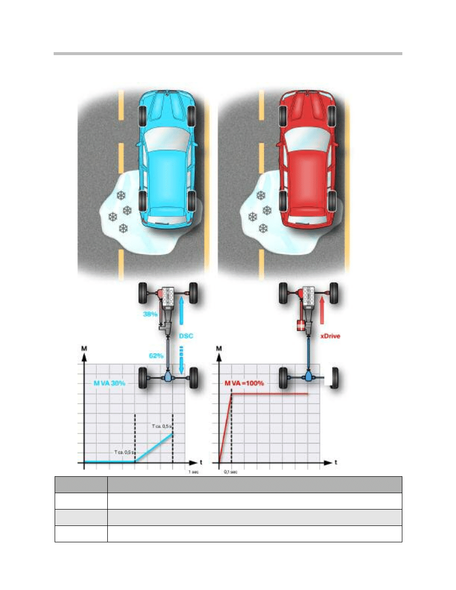
“Open” Transfer Case vs. xDrive
21
E60/E61 xDrive with DSC8+
Index
Explanation
M
Driving Torque
M VA
Driving torque on front axle
t
Time
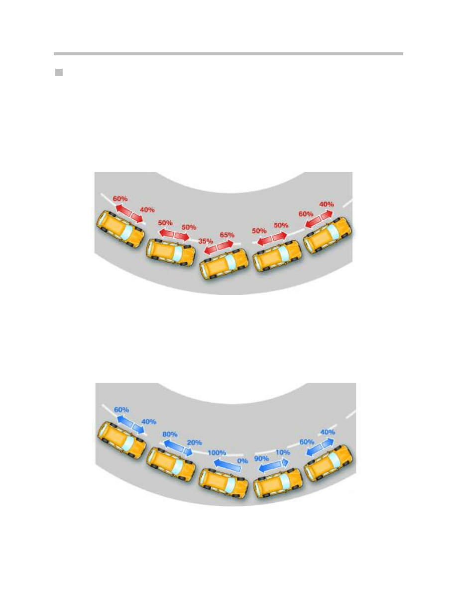
Traction Control / Driving Dynamics Control
Traction control monitors the slip conditions on the front and rear axles. The wheel
speeds, yaw rate and transversal acceleration serve as the input signals.
The function of traction control/driving dynamics control is to achieve optimum traction
and to keep the vehicle stable.
As seen in the following graphic, in the event of an oversteer tendency, the transfer case
clutch is completely engaged and the maximum supportable driving torque on the front
axle is transmitted. This helps to “pull’ the front of the vehicle until stability is achieved.
In the event of an understeer tendency, the clutch can be fully disengaged if necessary.
In this example, the front axle is separated from the drivetrain and the driving torque can
only be transmitted to the rear axle. This helps to “push” the rear of the vehicle until sta-
bility is achieved.
22
E60/E61 xDrive with DSC8+

Limp Home Operation
In order to maintain the four wheel drive function for as long as possible even in the event
of important sensor signal failures or failure of the DSC control unit, a limp home control is
integrated in the transfer case control unit. This control operates in redundancy to the
transfer case clutch control in the DSC control unit. The limp home control contains only
two control functions, pre-control and traction-slip control.
The wheel speed signals are very important to traction/slip control. Engine signals,
steering angle and yaw are used predominantly for pre-control. If individual sensor sig-
nals fail, substitute values are calculated and the relevant functions operated with extend-
ed control thresholds.
This strategy is continued until useful four wheel drive control is no longer possible. In
this event, the driver is alerted by the DSC/xDrive lamp coming on in the instrument clus-
ter and also by an acoustic warning signal (gong).
Faulted wheel speed signals on the rear axle are calculated by driving or engine speed
(remember, the rear wheels are always driven). If the front wheel speed signals fail, the
values of the rear axle are adopted. Wheel speeds also substitute for a faulty steering
angle signal.
Note: On a vehicle equipped with an automatic transmission, when driving
onto brake analyzers, move the selector lever to the “N” position . On a
vehicle equipped with a manual transmission, do not press the accelera-
tor pedal once on the brake analyzer. This keeps the transfer case clutch
open and the vehicle cannot be pulled off the analyzer.
23
E60/E61 xDrive with DSC8+

Dynamic Stability Control
DSC8+ offers several new features from April 2005 production vehicles. They are:
• ASC-X / ADB-X
• Hill descent control HDC
• Dry braking
• Brake standby
• Automatic soft stop
• Fading assistance
• Drive-off assistant
• Trailer stabilization control
ASC-X / ADB-X
Unlike regular road vehicles, SAVs are also meant to demonstrate satisfactory handling
characteristics and appropriate traction on unconventional roads. In order to provide opti-
mum propulsion with sufficient cornering stability on both normal roads and other road
surfaces, Automatic Stability Control X (ASC-X) contains a detection function to distin-
guish between them.
When off-road terrain is detected, wheel slip threshold is increased to provide sufficient
traction force with the increased levels of traction loss.
ASC-X is supplemented by the Automatic Differential Brake (ADB-X) function, which
applies the brakes to the wheels per axle, for side to side torque transfer. For example,
when a wheel is spinning on one side (up to the slip setpoint), the brakes are applied to
that wheel and the driving torque is transferred through the axle differential to the wheel
with the higher traction. This provides superb capabilities when there are diagonal trac-
tion losses (ie. left front/right rear).
ADB-X remains active when DSC is deactivated. Furthermore, ADB-X can develop full
capability because the engine power is not reduced, even during extreme four wheel
drive operation. Only that wheel which has a low traction receives the brake application.
The brake disc can overheat with excessive ADB-X intervention with DSC deactivated. In
this situation, the operation is discontinued at a disc temperature of approx. 700 ºC and is
resumed when this temperature drops below approx. 400 ºC. This is a calculation per-
formed by the DSC control unit based on brake application time, pressure, wheel speed,
etc.
24
E60/E61 xDrive with DSC8+
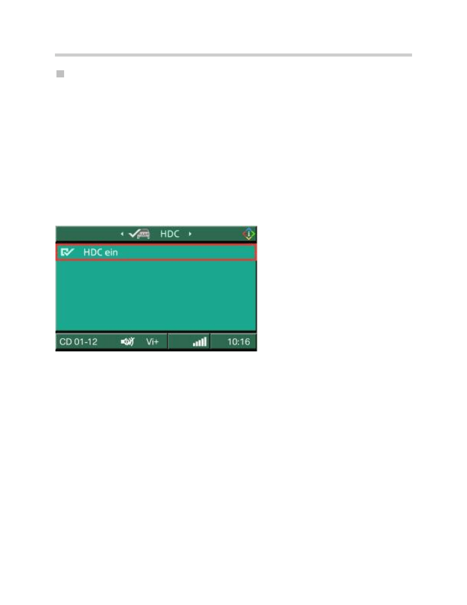
Hill Decent Control (HDC)
As on previous all wheel drive vehicles in the BMW line, the E61 all-wheel drive also fea-
tures the hill descent control facility for safe vehicle operation on steep downhill inclines.
The HDC stabilizes the vehicle and prevents the wheels locking. The DSC8+ module
controls the build-up of braking pressure at all four wheels so that the vehicle drives
downhill at a speed of approx. 7.5 mph (12 km/h).
The HDC function is activated in the central information display via the menu:
Settings => Vehicle settings => HDC
The HDC ON function can be activated by setting a tick in the menu and deactivated by
removing the tick.
Furthermore, the HDC ON/OFF function can be selected with one of the two free but-
tons (asterisk, hash) in the steering wheel button menu.
25
E60/E61 xDrive with DSC8+
Menu HDC ON / Active

Dry Braking
The water spray produced in wet conditions coats the brake discs with a water film, caus-
ing delayed response of the brakes. In connection with previous systems it was therefore
recommended to operate the brakes from time to time.
The dry braking function is dependent on the position of the wiper switch and therefore
on the signal of the rain/lights sensor. The brake discs are kept dry by lightly applying the
brake pads cyclically as required, this achieving improved braking response in wet condi-
tions.
While doing so, the pressure in the brake system is increased by approx. 1 bar and the
brake pads are applied for approx. 1.5 seconds.
Dry braking takes place under following conditions:
• Driving speed > 70 km/h
• Continuous wipe operation in stage 1 or 2
The repeat interval depends on the wiper stage:
• Continuous wipe stage 1 - 200 s
• Continuous wipe stage 2 - 120 s
• Generally 90 s as from 09/2005
This applies only when the driver himself does not apply the brake during this time.
The driver notices no deceleration or noise.
26
E60/E61 xDrive with DSC8+
Left disc with water film before dry braking Right brake disc after dry braking

Brake Standby
Quick release of the accelerator pedal causes the brake pads to be applied against the
brake disc thus reducing the stopping distance (by approx.. 30 cm/100 km/h) during
emergency braking. The DSC module builds up slight brake pressure (approx. 2.5 bar)
temporarily (approx. 0.5 seconds) in order to eliminate the clearance between the brake
pad and brake disc by applying the brake pads.
The brake standby function is activated under following conditions:
• Driving speed > 70 km/h
• Minimum time between brake application 8 s
• The brake standby function is not activated in connection with sudden acceleration
(sports driving style).
The DME/DDE control unit makes available the signal indicating quick release of the
accelerator pedal via the PT-CAN.
The sensitive driver may perceive a slightly harder brake pedal. No delay or noise is dis-
cernible for the driver.
Index
Explanation
P
Braking pressure in Bar
T
Time in milliseconds
1
Pilot pressure applied by driver
2
Braking pressure progression with brake standby
3
Braking pressure progression without brake standby
27
E60/E61 xDrive with DSC8+

Automatic Soft Stop
Due to the transition from sliding friction to static friction on the brake disc, a stopping jolt
occurs when braking to a standstill where the occupants perceive an increased feeling of
deceleration.
When braking lightly (< 25 bar) at constant pressure to bring the vehicle to a halt, the soft
stop function automatically reduces the braking pressure at the rear axle just before the
vehicle comes to a stop. This consequently reduces the positive acceleration peak per-
ceived by the occupants by approx. 50% while extending the action time.
The speed and standstill status are recognized by way of the wheel speed sensors.
Note: This function is inactive at medium to high deceleration or in the event of
ABS control in order not to lengthen the stopping distance.
28
E60/E61 xDrive with DSC8+
Index
Explanation
m/s2
Deceleration
s
Time in seconds
Red
Deceleration without soft stop
Blue
Deceleration with soft stop
-50%
Reduction of occupant deceleration

Fading Compensation
High temperatures (> 550°C) can occur at the brake discs when driving downhill over
long periods or as the result of extreme multiple braking operations ( > 80 bar). These
high temperatures cause a change in the coefficient of friction of the brake pads resulting
in the braking effect diminishing (fading).
For this purpose, the temperature of the brake disc is calculated by means of a tempera-
ture model contained in the DSC8+ software. The braking pressure applied by the driver
is measured by the delivery pressure sensor and compared with the current vehicle
deceleration (target/actual value).
When the braking effect diminishes, the fading compensation provides assistance for the
driver in that pressure is additionally built up by the DSC module.
29
E60/E61 xDrive with DSC8+
Brake Disc with Fading

Drive-off Assistant
When negotiating uphill gradients, the drive-off assistant holds the vehicle for a short time
(approx. 1.5 s) after releasing the brake so that the vehicle drives off comfortably without
the need to use the handbrake. The braking pressure required by the driver to hold the
vehicle is maintained automatically in the system.
When driving off, the braking pressure is not reduced before the torque is sufficient for
the vehicle to drive off. The holding pressure in the brake system (10 to max. 70 bar) is
dependent on the uphill gradient.
Uphill gradients are detected by the DSC sensor with the aid of a longitudinal accelera-
tion sensor.
The function is active both when driving forwards (transmission in Drive) and when
reversing (transmission in Reverse) on uphill gradients (up to 50 %).
30
E60/E61 xDrive with DSC8+
Drive-off Assistant Function

31
E60/E61 xDrive with DSC8+
NOTES
PAGE

Service Information
On a vehicle equipped with an automatic transmission,
when driving onto brake analyzers, move the selector
lever to the “N” position . On a vehicle equipped with a manual transmission,
do not release the clutch pedal once on the brake analyzer.
This keeps the transfer case clutch open and the vehicle cannot be pulled
off the analyzer.
Oil, Transfer Case, and Clutch Monitoring
Oil
All xDrive transfer cases use Shell Gear oil part number 83 22 0 306 816.
There is no scheduled service for the transfer case oil. Oil Monitoring is performed by the
VTG control module to determine when a service (change) is due. The VTG calculates
transfer case and clutch wear based on the amount of slip, engagement pressure
(torque), speed and mileage.
This calculation accounts for:
• normal “dry” road driving (Integrator 1)
• “adverse” road driving (Integrator 2)
• “other” road extreme driving (Integrator 3)
Depending on individual vehicle use - driving styles and driving conditions, the transfer
case oil service interval will vary.
When a service is due, this will be indicated by a Fault Code and additional details are
available using the DISplus/ GT1. Service functions provide directions on changing the
transfer case oil and updating the VTG control module with the necessary reset and
adaption procedure. This is extremely important for CBS.
Transfer Case and Clutch
The transfer case and clutch have separate monitoring characteristics. These values are
stored as adaptive values in the VGSG control unit and must be transferred to a new con-
trol unit if replaced.
The value for both can be obtained using the diagnostic software under:
Control Unit Functions => VTG => Diagnosis requests => Transmission
Control Unit Functions => VTG => Diagnosis requests => Clutch
32
E60/E61 xDrive with DSC8+
Safety Notice!!!
Towing: Use only a flatbed carrier for all xDrive vehicles!

Diagnosis
Diagnosis is available for fault repairs and service procedures using the DISplus/GT1.
The test plan for the VGSG contains valuable information on:
• Replacing control unit
• Replacing transfer case
• Transferring adaptation values
- Automatic
- Manual
• Reading out adaptation values
Programming (flashing)
Both the transfer case control unit (VTG) and the DSC control unit are programmable and
the new control unit(s) must be programmed when replaced. The wear values stored in
the VTG control module (to be replaced) must be transferred to the replacement VTG.
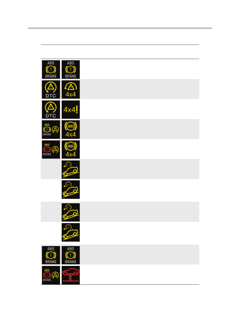
Warning Indicator Lamps
The warning indicator lamps for the xDrive / DSC are found in the instrument cluster as
shown on the bottom of this page.
The warning indicator lamps and acoustic signals (gong) are assigned to the xDrive / DSC
system states of malfunction described on the next two pages.
33
E60/E61 xDrive with DSC8+

34
E60/E61 xDrive with DSC8+
Fixed
indicator
lamp
Variable
indicator
lamp
Check control
message
Information in central information display
DSC disabled!
You have disabled DSC. Restricted vehicle stability
while accelerating and cornering.
DTC enabled,
DSC restricted!
DTC enabled.
Dynamic traction control DTC increases forward
propulsion on unpaved surfaces, however, it
decreases vehicle stability.
DSC failed!
Drive with
moderation
DBC failed.
No additional braking assistance from DBC in
emergency braking situations.
Drive with moderation.
Have checked by your BMW dealer as soon as
possible.
DSC failed!
Drive with
moderation
DSC failed.
Restricted vehicle stability while accelerating and
cornering.
Drive with moderation.
Have checked by your BMW dealer as soon as
possible.
Control systems!
Drive with
moderation
Brake and vehicle control systems failed. Reduced
braking and vehicle stability. Avoid abrupt braking
where possible.
Have checked by nearest BMW dealer.
Control systems!
Drive with
moderation
Brake and vehicle control systems failed. Drive
with moderation, avoid abrupt braking where
possible. Have checked by nearest BMW dealer.
Brake pads!
Replace
The brake pads are worn.
Have replaced by nearest BMW dealer.
Brake fluid!
Stop cautiously
Brake fluid level too low. Reduced braking
efficiency. Stop cautiously. Contact nearest BMW
dealer.
Brakes too hot!
Allow to cool
down
Brakes too hot
Critical temperature as a result of permanent
heavy load. Danger - reduced braking efficiency.
Allow brakes to cool down. Stop if necessary.
Check Control Messages Relating to xDrive / DXC8+
35
E60/E61 xDrive with DSC8+
Brakes
overheated!
Allow to cool
down
Brakes overheated
Critical temperature exceeded. Braking efficiency
no longer guaranteed. Stop at the next opportunity
and allow to cool down substantially.
4x4 system and
DSC failed!
4x4 system and DSC failed! Vehicle stability
restricted. Drive with moderation. Have checked
by your BMW dealer as soon as possible.
4x4 system
defective!
Drive with
moderation
4x4 system defective
Vehicle stability restricted. Drive with moderation.
Have checked by your BMW dealer as soon as
possible.
4x4 system, DSC
and ABS failed!
4x4 system, DSC and ABS failed! Vehicle stability
restricted. Drive with moderation. Have checked
by your BMW dealer as soon as possible.
4x4 System,
DSC, ABS and
emergency EBV
failed!
4x4 System, DSC, ABS and emergency EBV
failed! Vehicle stability restricted. Drive with
moderation. Have checked immediately by your
BMW dealer.
HDC enabled!
HDC disabled!
HDC disabled.
Hill descent control HDC is disabled at speed
above 60 km/h (37 mph).
System can be re-enabled at speed below 35 km/
h (22 mph).
No HDC control!
Drive slower
HDC not possible!
Control range ends at
35 km/h (22 mph). To use HDC, reduce speed
accordingly.
HDC currently
not available!
HDC not available.
Automatic brake intervention interrupted for safety
reasons as brakes are overheated.
Shift down and drive carefully in order to reduce
temperature.
Drive-off
assistant
inactive!
Drive-off assistant inactive
Caution, vehicle can roll back! Have checked by
your BMW dealer at next opportunity.
Electronics fault!
Stop cautiously
Central vehicle electronics failed. Continued
journey not possible. Contact nearest BMW
dealer.
Fixed
indicator
lamp
Variable
indicator
lamp
Check control
message
Information in central information display
Check Control Messages Relating to xDrive / DXC8+ (cont’d)
Document Outline
- Main Menu
- Introduction to Chassis Dynamics
- Steering Systems
- Active Steering
- Electric Power Steering
- Traction and Stability Systems
- DSC
- DSC8+
- xDrive with DCS8
- xDrive with DCS8+
- Active Roll Stabilization
- Level Control Systems
- EHC and EHC II
- E61 Rear Air Suspension
- Electronic Damping Control
- Braking Systems
- Tire Pressure Monitoring Systems
Wyszukiwarka
Podobne podstrony:
03b 1 E83 E53 xDrive with DSC8
BMW E60, 61 AC Schnitzer chipy
Image Processing with Matlab 33
plik (61)
L 5590 Short Sleeved Dress With Zipper Closure
61 62
M 5190 Long dress with a contrast finishing work
61 65
61 MT 03 Pila tarczowa
O'Reilly How To Build A FreeBSD STABLE Firewall With IPFILTER From The O'Reilly Anthology
61 (2012) streszczenia id 44220 Nieznany
M 5450 Dress with straps
61 MT 02 Kolka profilowane
59 61
58 61
Dance, Shield Modelling of sound ®elds in enclosed spaces with absorbent room surfaces
61 63
drzwi czech e60 EASY 719 DC RC
więcej podobnych podstron