
Hook into
this fantastic
rod rack
TM
page 1 of 9
DOWNLOADABLE PROJECT PLANS FROM THE EDITORS OF WOOD MAGAZINE
http://www.woodmagazine.com
If you’re a
fisherman who has
everything—and
nowhere to store
anything—take
heart. With this
handsome piece
hanging in your den
or basement, you’ll
have a haven for six
rods and reels, a
creel or tackle box,
and that favorite
vest that’s never had
the good luck
washed out of it.
Hook into
this fantastic
rod rack
TM
page 2 of 9
SHELF RECESS DETAIL
Front edge
C
15
0
A
B
E
F
G
D
C
E
D
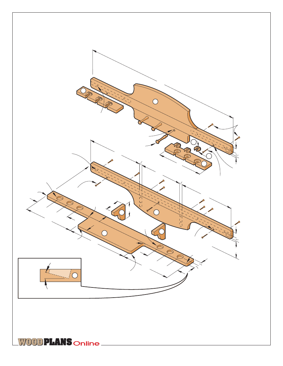
42"
#8 x 1
1
/
2
"
F.H. wood
screws
5
/
32
" shank hole
countersunk
#8 x 2
1
/
2
"
F.H. wood screw
12"
1
/
2
" hole
5
/
8
" deep
3
1
/
2
" Shaker peg
14
5
/
8
"
14
5
/
8
"
11
1
/
4
"
3
/
4
"
3
/
4
"
#8 x 1
1
/
2
"
F.H. wood screws
1
1
/
4
"
3
/
4
"
1
/
2
"
1
1
/
4
"
3
/
4
"
1
/
2
"
4
1
/
2
"
#8 x 2
1
/
2
"
F.H. wood screws
5
/
32
" shank hole
countersunk
4"
4"
5
/
32
" shank holes
countersunk on back
side;
7
/
64
" pilot holes are
3
/
4
" deep
2
1
/
4
"
1
1
/
4
"
1
1
/
2
" hole
1
/
2
" deep
3"
3"
3"
1
/
2
" radius
1
/
2
" radius
1" radius
1
1
/
2
" hole
1
/
2
" deep
3"
3"
3"
13"
16"
13"
8"
1
/
2
" radius
1
/
2
" radius
1" radius
5
/
32
" shank holes countersunk
on back side;
7
/
64
" pilot holes
are
3
/
4
" deep
EXPLODED
VIEW
1◊ı" dia.
1›"
TM
page 3 of 9
›"
¤"
4"
‡"
3fi"
‡"
E rod retainers
2
W
12"
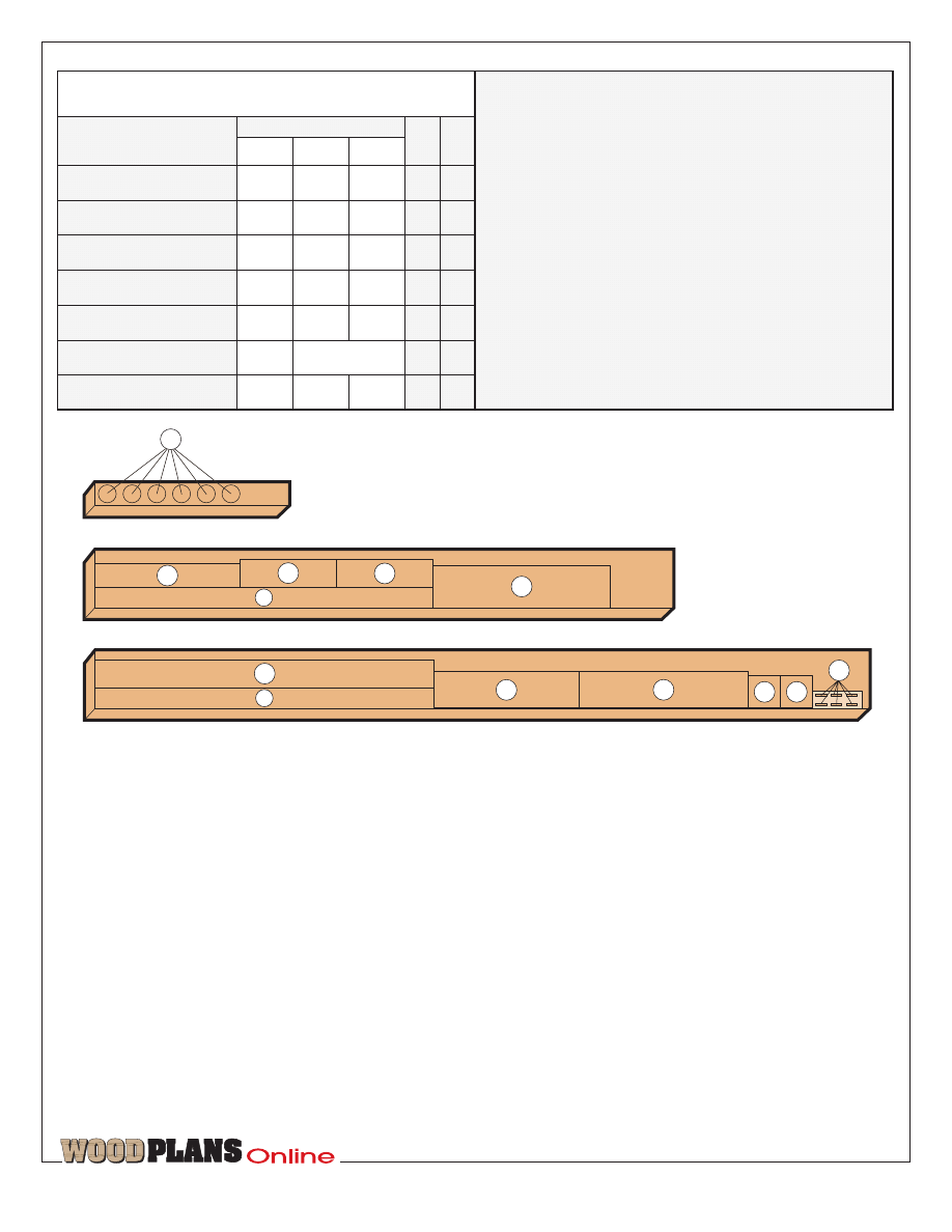
Part
EW
1
B* lower back
42"
Bill of Materials
D brackets
EW
1
42"
‡"
8"
W
2
4"
Qty.
A* upper back
42"
‡"
10fi"
EW
1
T
W
L
Finished Size
Matl.
‡"
7"
C* shelf
G disc handles
6
W
F discs
6
M
‹"
*Edge-join this part during construction. Please read
all instructions before cutting.
Materials Key: W—walnut; EW—edge-joined walnut;
M—maple.
Supplies: #8
×
1fi", #8
×
2fi” flathead wood screws;
3fi” walnut Shaker pegs; adhesive-backed felt;
tung-oil finish; fast-drying polyurethane spray.
3
/
4
" x 7
1
/
4
" x 48" Walnut
CUTTING DIAGRAM
3
/
4
" x 7
1
/
4
" x 72" Walnut
B
C
D
D
G
C
B
A
E
E
A
A
3
/
4
" x 2" x 16" Maple
F
First, edge-join
and bandsaw the big parts
1 To make the upper back (A), the
lower back (B), and the shelf (C), start
with 96" and 72" lengths of ‡
×
7‹"
stock. (We selected walnut.) Using the
Cutting Diagram for reference, rip and
crosscut the pieces for these parts to
the following dimensions: 2fl
×
43",
3¤
×
19", and 5›
×
23" for the upper
back; 3fl
×
43" and 4fl
×
19" for the
lower back; and 2fl
×
43" and 4fl
×
22"
for the shelf.
2 Use your jointer to plane the mating
edges of all pieces where shown on
the Exploded View drawing. Mark
these mating surfaces. Now, edge-glue
and clamp the upper back, lower back,
and shelf. Wipe off any glue squeeze-
out with a damp cloth, and allow the
glue to dry.
3 Rip and crosscut two brackets (D)
to 4
×
4" and two rod retainers (E) to
3fi
×
12" where shown on the Cutting
Diagram. Draw a fi" radius at each
front corner of the retainers where
shown on the Rod Retainer drawing
on page 4, and bandsaw to shape.
4 Stack the two brackets using double-
faced carpet tape. Lay out the gridded
Upper Back, Lower Back, and Bracket
patterns shown on page 7 in full size
on large sheets of paper. (We keep a
roll of butcher paper in our shop for
this purpose.
Cut out and adhere the patterns to the
stock. (We used a spray adhesive.)
Now, bandsaw the pieces to shape,
keeping your blade outside the line.
(We used a ‹" blade.)
5 Chuck a coarse-grit, 1"-diameter
drum sander into your drill press, and
sand the bandsawed parts to the line.
Now, follow up with a fine-grit drum
sander.
6 Lay out and countersink shank holes
on the back face of the upper back and
lower back where shown on the
gridded patterns and as dimensioned
on the Exploded View drawing.
Position and clamp the shelf, brackets,
and rod retainers, then drill the pilot
holes to the dimensions shown.
TM
page 4 of 9
1
1
/
2
" multi-spur bit
Right-angled
fence
15
°
wedge
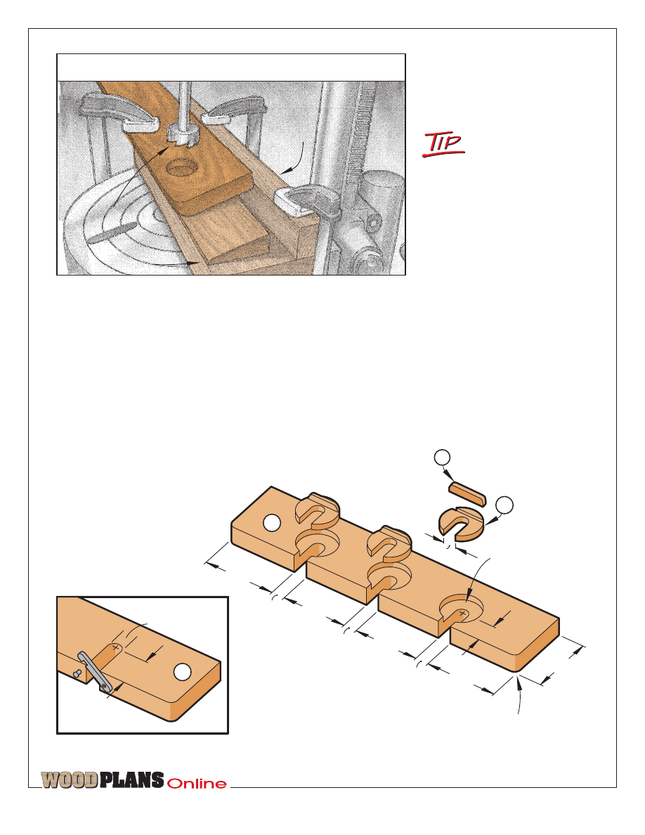
DRILLING THE SHELF RECESSES
E
CATCH OPTION
E
F
G
1
/
2
"
1
1
/
4
"
3
1
/
2
"
2
3
/
4
"
2
1
/
2
"
2
1
/
2
"
2
3
/
4
"
1
/
2
"
1
/
2
"
1
/
2
"
ROD RETAINER
1
1
/
2
" recess
1
/
4
" deep
1
/
2
" radius
1
1
/
4
"
1
/
2
"
your fence ‡" from the blade, and
bevel-cut the piece. Make a right-
angled fence from two 18" lengths of
1fi"-thick scrap as shown above.
Position and clamp it to your drill-
press table. Clamp the wedge and a
‡
×
3fi
×
18" scrap piece to the fence to
test your depth setting. Chuck a 1fi"
multi-spur bit into your drill press, and
bore test holes to adjust the depth on
the deep side of the recess to fi".
Now, clamp the shelf and wedge to
the fence as shown, and bore the six
recesses. (We set our drill-press speed
at 250 rpm.)
2 Lay out and bore the three recesses
in each rod retainer where shown on
the Rod Retainer drawing. (We first
bored some 1fi"-diameter test holes
in a piece of scrap to adjust the depth
to ‹". After we bored our rod retainers,
we bored seven more recesses in this
scrap piece, marked these recesses
“good,” and saved the piece for later
use.)
3 Bore a centered fi" hole through
each recess in the rod retainers.
(We used our drill press for the shank
holes, our portable drill with a depth
stop for the pilot holes, and brad-point
bits for both.) Now, unclamp the parts.
7 Lay out and bore three fi" holes fl"
deep on the upper back for the Shaker
pegs where shown on the gridded
pattern. (We used a Forstner bit in our
drill press.)
Make the rod-holding recesses,
then assemble your rack
Note: For a simpler rod-holding
alternative, see the Catch Option detail
on the Rod Retainer drawing below.
1 Lay out the recesses on the shelf
where shown on the Exploded View
drawing. Cut a 15° wedge from a
3
×
18" piece of ‡"-thick scrap.
To do this, tilt your tablesaw
b l a d e t o 1 5 ° f r o m
perpendicular, set
To separate stock
pieces adhered with
double-faced carpet
tape, splash a bit of acetone
or lacquer thinner on the
edges, and allow it to penetrate
the adhesive.
TM
page 5 of 9
(We used a Forstner bit and a backup
board to prevent tear-out.) To cut slots
in the rod-retainer recesses, fit your
tablesaw with a fine-toothed blade,
and set the blade height to 1‹". Use
your combination square to lay out the
slots on the back face of the rod
retainers where shown on the Rod
Retainer drawing. Attach a wooden
auxiliary fence to your miter gauge,
and stand each rod retainer on its front
edge against the fence. Align the blade
with the lines you laid out, clamp the
rod retainer to the fence, and cut the
slots.
4 Fit your table-mounted router with
a „" round-over bit, and rout the
front edges of the upper and lower
backs. Now, rout all edges of the shelf,
rod retainers, and brackets except those
on the mating surfaces.
5 Finish-sand all parts. (We used a
palm sander with 100-, 150-, and then
220-grit sandpaper.) Next, sand three
3fi" walnut Shaker pegs with fi"-
diameter tenons. (We found ours at a
local hardwood lumber store.) Glue
them into the holes on the upper back.
Then, assemble all parts using glue
and #8
×
1fi" flathead wood screws.
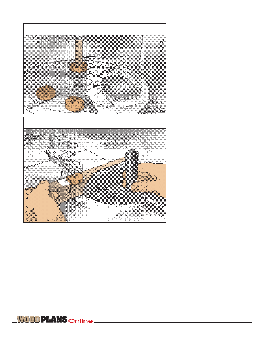
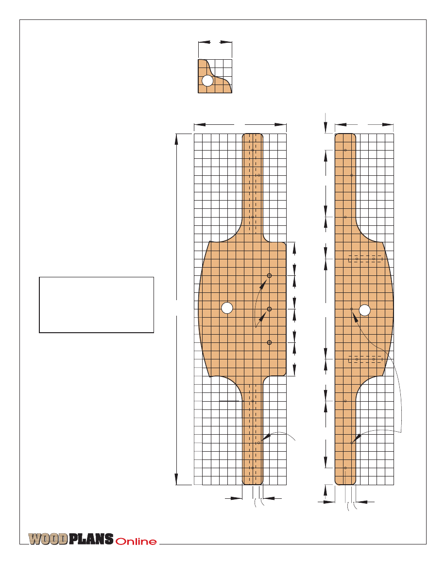
Now, machine
the rod-holding discs
1 On a ‡
×
2
×
16" piece of contrasting
stock, lay out six or seven discs (F) as
dimensioned on the Disc drawing at
right. (We chose maple and laid out
seven discs so we’d have a spare.) To
do this, mark a line 1" from the end
and every 2" thereafter. At each mark,
use your combination square to lay
out a perpendicular ¤"-wide handle
slot across the face and both edges.
Then, lay out a centerpoint for each
disc where shown. (Note: In laying
out your discs, make sure that the
handle slots run across the grain.)
2 Cut the discs using a circle-cutting
bit in your drill press. First, turn the
vertical edge of the bit to the inside to
cut a clean disc (rather than a clean
hole). Next, adjust the diameter to
1¸". Set the depth of cut to fl", then
run a couple of test discs to check the
diameter and depth.
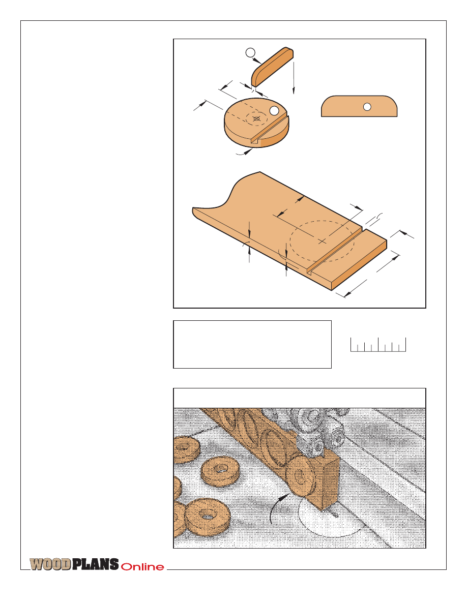
Saw off the top
5
/
16
" of
3
/
4
" stock
BANDSAWING THE DISCS
G
FULL-SIZED
PATTERN
Handle
F
G
1
/
2
"
1
1
/
2
" diameter
1
/
8
"
1"
3
/
4
"
1
/
8
"
1
/
8
"
3
/
8
"
2"
DISC LAYOUT
1"
DISC
fi
‹
‡
1"
SCALE
To ensure full-sized patterns are correct
size, your printer should be set to print
at 100% (not fit to page). Measure full-
sized patterns to verify size.
TM
page 6 of 9
1
/
2
" dowel
Disc with handle
Hand-held
sanding block
SANDING THE DISCS
Double-faced
carpet tape
Disc
handle
Auxiliary wooden fence
attach to miter gauge
BANDSAWING THE DISC SLOTS
3 Enlarge the ‹" holes made by the
circle-cutting bit to fi". (We used a
Forstner bit.) Now, use your tablesaw
and miter gauge to cut the ¤"-wide
handle slots ¤" deep. To do this, set
your blade height to ¤", and attach an
auxiliary wooden fence to your miter
gauge.
4 Next, use your bandsaw and fence
to slice off the discs to a thickness of
ˇ" as shown on page 5. Insert the
discs in the seven “good” recesses on
the scrap piece you bored in Step 2 of
the previous section. Sand one face
and then the other until the discs are
flush with the surface.
5 Make the disc handles (G) by first
ripping and crosscutting a 2
×
12" piece
of leftover walnut stock. Use your
bandsaw and fence to saw a ¤"-thick
slice off the face. Sand the piece
smooth on both faces, then crosscut it
in half. Stack the halves using double-
faced carpet tape. Adhere three copies
(or four if you made seven discs) of
the full-sized Disc Handle pattern
shown on page 7 to one face. (We
photocopied ours and adhered them
using a spray adhesive.) Saw the
handles to shape, separate the pieces,
and glue a handle into each disc slot.
6 When the glue has dried, sand the
disc edges (including the handles) until
they turn freely but still fit snugly in
the recesses. (We chucked a fi" dowel
into our drill press and fitted each disc
onto the end of it as shown opposite.
Then, we hand-held a sanding block
with 120-grit sandpaper and ran our
drill press at 500 rpm.) Now, sand the
handle edges as necessary. (We used
our stationary disc sander.)
7 Next, bandsaw the fi"-wide slot in
each disc. (We attached a 1
×
1fi
×
12"
auxiliary wooden fence with the edge
up to our bandsaw miter gauge as
shown. We adhered a strip of double-
faced carpet tape across the fence and
then sawed a kerf two-thirds of the
way through the fence and tape. We
adhered each disc to the tape facedown,
butting the handle up against the back
face of the fence and aligning one edge
of the hole with the kerf. We
bandsawed one side of the slot on all
discs, then repositioned the fence to
saw the other side.)
You’re nearly ready
to display your gear
1 Apply the finish of your choice to
the rack and the discs. (We brushed a
tung-oil finish on the rack, wiped off
the excess, and allowed it to dry for
six hours. We repeated this procedure
until we had applied three coats,
allowing the third coat to dry overnight.
Then, we sprayed on a coat of fast-
drying semigloss polyurethane as a
sanding sealer. We sanded lightly with
320-grit sandpaper, then sprayed on
two additional coats, sanding between
coats. We used 000 synthetic steel
wool to smooth the contoured surfaces.
Finally, we sprayed the discs with two
coats of fast-drying polyurethane.)
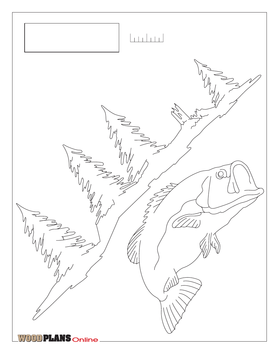
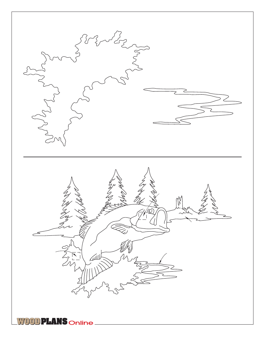
2 Allow all parts to dry overnight.
Then, scrollsaw a decorative scene if
you wish, and adhere it to the center
of the upper back. We sprayed our
scrollsawed pieces with two coats of
fast-drying polyurethane.
Produced by: Marlen Kemmet
Project Design: Bob Colpetzer
Illustrations: Roxanne LeMoine
Graphic Design: Jamie Downing
©COPYRIGHT MEREDITH CORPORATION 1997
The purchase of these plans does not
transfer any copyright or other ownership
interest in the plans, the design, or the
finished project to the buyer. Buyer may
neither reproduce the plans for sale nor
offer for sale any copies of the finished
project.
TM
page 7 of 9
When the polyurethane had dried, we
mounted them using Franklin
Countertop contact cement, a low-
odor, nonflammable adhesive we
bought at our local home center.)
3 Line the bottoms of the shelf recesses
with adhesive-backed felt. (We used
kelly-green felt, which we found at a
local crafts store.)
4 Locate three consecutive studs in
the wall you’ve selected. Lay out and
drill ¸" countersunk shank holes
through the front faces of both
assemblies (two holes on the upper
back and three on the lower back)
where shown on the gridded patterns.
Drill
7
/
64
" pilot holes 1‡" deep in
the studs, and mount the rack using
#8
×
2fi" black flathead wood
screws. ¿
B
2"
8"
5"
12"
5"
8"
2"
7"
5
/
32
" shank holes
1
1
/
4
"
3
/
4
"
1
/
2
"
A
4"
4"
4"
4"
1
1
/
4
"
3
/
4
"
1
/
2
"
1
/
2
"holes
5
/
8
" deep
11
"
42"
5
/
32
" shank holes
One square = 1 inch
One square = 1 inch
GRIDDED
P
A
TTERNS
Upper bac
k
Lo
wer bac
k
D
4"
One square = 1 inch
Brac
ket
TM
page 8 of 9
fi
‹
‡
1"
SCALE
To ensure full-sized patterns are correct
size, your printer should be set to print
at 100% (not fit to page). Measure full-
sized patterns to verify size.
FULL-SIZED PATTERNS
TM
page 9 of 9
‹" x ‹"
Layer 2
Spacer block
Layer 1
Layer 3
Layer 2
Layer 1
‹" x Ï⁄Â"
x Ï⁄Â"
Layer 1
Spacer block
FULL-SIZED PATTERNS
Wyszukiwarka
Podobne podstrony:
Fishing Rod Holder
beginner project fishing pole rack
Growing Rack
Key Rack
Herb Drying Rack
Drying Rack
Popular Mechanics Replacing A Steering Rack
Clothes Rack
62 STEERING GEAR POWER RACK & PINION
Bathroom Towel Rack
Magazine Rack
Growing Rack
wine rack
Billiards Cue Rack and Scoreboard (Part 2)
eCourse Wine Rack FAQs
Pot And Pan Rack
Pool Cue Ball Rack
beginner project cd rack
więcej podobnych podstron