
2009 ENGINE
Ignition Control - Service Information - Grand Caravan, Town & Country
DESCRIPTION
DESCRIPTION
The 3.3/3.8L engines use a distributorless ignition system and is commonly referred to as Direct Ignition
System (DIS). The 4.0L engine uses a Coil on Plug design. The system's main components are the ignition
coils, crankshaft position sensor, camshaft position sensor and spark plugs.
OPERATION
OPERATION
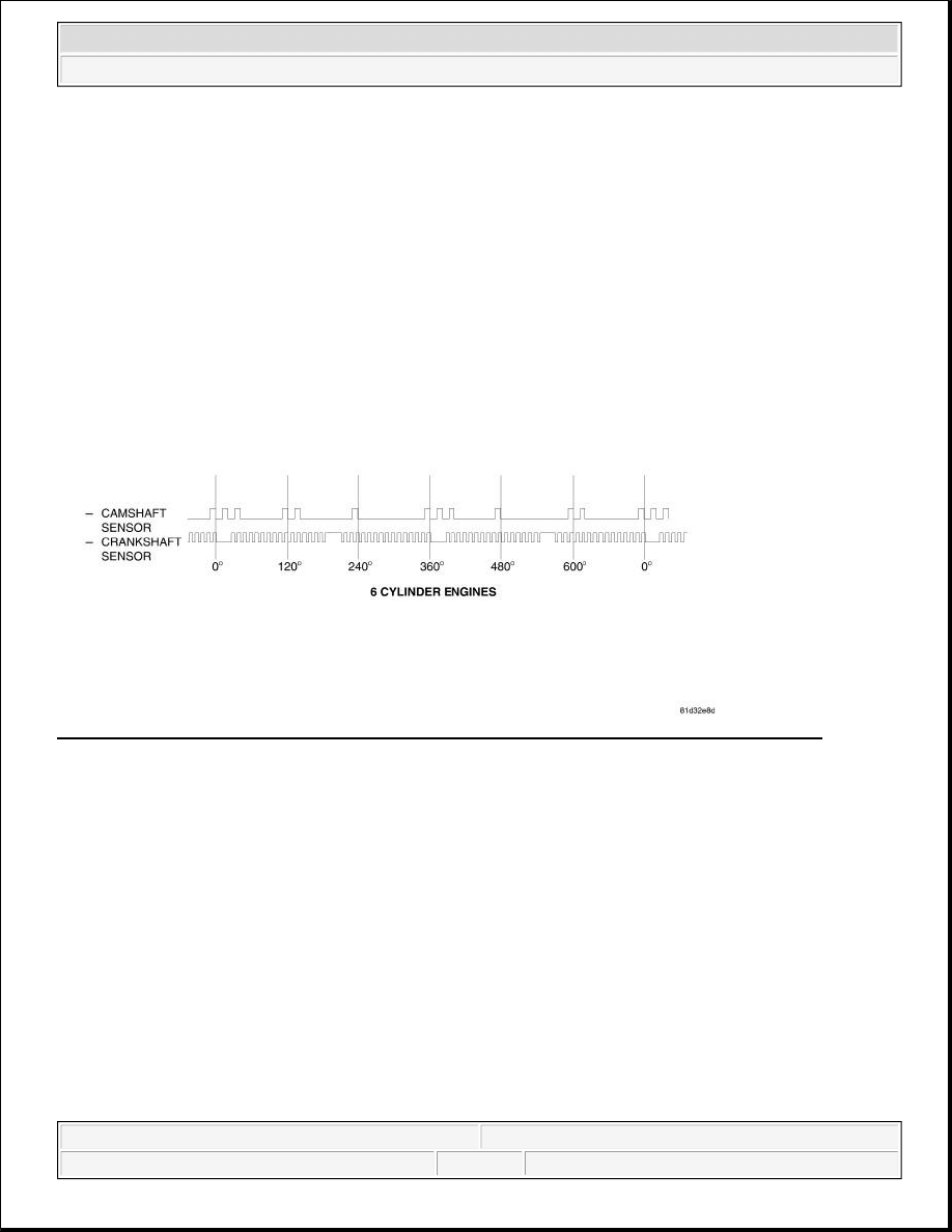
The crankshaft position sensor and camshaft position sensor are hall effect devices. The camshaft position
sensor and crankshaft position sensor generate square wave pulses that are inputs to the PCM. The PCM
determines engine position from these sensors. The PCM calculates injector sequence and ignition timing from
crankshaft AND camshaft position.
SPECIFICATIONS
FIRING ORDER
3.3/3.8L
NOTE:
All engines use a fixed ignition timing system. Basic ignition timing is not
adjustable. All spark advance is determined by the Powertrain Control Module
(PCM).
2009 Chrysler Town & Country LX
2009 ENGINE Ignition Control - Service Information - Grand Caravan, Town & Country
2009 Chrysler Town & Country LX
2009 ENGINE Ignition Control - Service Information - Grand Caravan, Town & Country
steve
Monday, May 30, 2011 12:02:11 PM
Page 1
© 2006 Mitchell Repair Information Company, LLC.
steve
Monday, May 30, 2011 12:02:14 PM
Page 1
© 2006 Mitchell Repair Information Company, LLC.
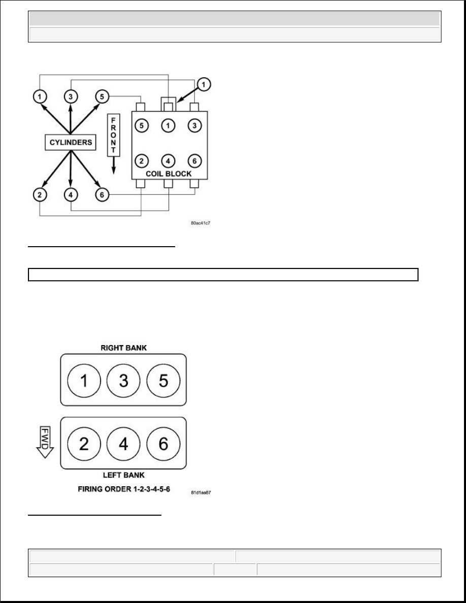
Fig. 1: Firing Order - 3.3/3.8L Engine
Courtesy of CHRYSLER LLC
The firing order is 1-2-3-4-5-6.
4.0L
Fig. 2: Firing Order - 4.0L Engine
Courtesy of CHRYSLER LLC
The firing order is 1-2-3-4-5-6.
1 - Electrical Connector
2009 Chrysler Town & Country LX
2009 ENGINE Ignition Control - Service Information - Grand Caravan, Town & Country
steve
Monday, May 30, 2011 12:02:11 PM
Page 2
© 2006 Mitchell Repair Information Company, LLC.

IGNITION RESISTANCE
IGNITION CABLE RESISTANCE
IGNITION CABLE RESISTANCE
IGNITION COIL RESISTANCE
IGNITION COIL RESISTANCE
SPARK PLUGS
SPARK PLUGS
TORQUE
TORQUE
MINIMUM
MAXIMUM
250 Ohms Per Inch
750 Ohms Per Inch
3000 Ohms Per Foot
9,000 Ohms Per Foot
Manufacturer
Engine
Primary Resistance at
21°C-27°C (70°F-80°F)
Secondary Resistance at
21°C-27°C (70°F-80°F)
Diamond Electric Mfg.
Corporation
3.3, 3.8L
0.530 to 0.650 ohms
10.9K to 14.7K ohms
Diamond Electric Mfg.
Corporation
4.0L
0.495 to 0.605 ohms
5.13K to 6.27K ohms
Engine
Spark Plug
Electrode Gap
Thread Size
3.3/3.8L
RE14PLP5
1.27 mm (0.050 in.)
M14 X 1.25
4.0L
ZFR5LP-13G
1.27 mm (0.050 in.)
M14 X 1.25
DESCRIPTION
N.m
Ft. Lbs.
In. Lbs.
Camshaft Position Sensor
Bolt 2.8L
5.4
-
48
Camshaft Position Sensor
Bolt 3.3/3.8L
14
10
-
Camshaft Position Sensor
Bolt 4.0L
12
9
-
Knock Sensor 3.3/3.8L
20
15
-
Knock Sensor 4.0L
20
15
-
Ignition Coil Bolt 4.0L
8
-
71
Ignition Coil Capacitor Bolt
4.0L
28
20.5
-
Ignition Coil Nuts 3.3/3.8L
12
-
106
Spark Plug 3.3/3.8L
17.5
13
-
2009 Chrysler Town & Country LX
2009 ENGINE Ignition Control - Service Information - Grand Caravan, Town & Country
steve
Monday, May 30, 2011 12:02:11 PM
Page 3
© 2006 Mitchell Repair Information Company, LLC.

CABLE, IGNITION
REMOVAL
REMOVAL
Disconnect and isolate negative battery cable at battery.
Remove spark plug cable from coil first.
Always remove the spark plug cable by grasping the top of the spark plug insulator, turning the boot 1/2 turn
and pulling straight up in a steady motion.
INSTALLATION
INSTALLATION
Failure to route the cables properly could cause the radio to reproduce ignition noise, cross ignition of the spark
plugs or short circuit the cables to ground. Install spark plug insulators over spark plugs. Ensure the top of the
spark plug insulator covers the upper end of the spark plug tube, then connect the other end to coil pack.
Install negative battery cable to battery.
CAPACITOR, IGNITION
REMOVAL
REMOVAL
Spark Plug 4.0L
27
20
-
Negative Battery Cable Nut
5
-
45
WARNING:
Always turn the engine off and disconnect the battery prior to servicing
the spark plug cables. Do not attempt to remove a spark plug cable while
the motor is running. Failure to follow these directions may result in
serious or fatal injury.
2009 Chrysler Town & Country LX
2009 ENGINE Ignition Control - Service Information - Grand Caravan, Town & Country
steve
Monday, May 30, 2011 12:02:11 PM
Page 4
© 2006 Mitchell Repair Information Company, LLC.
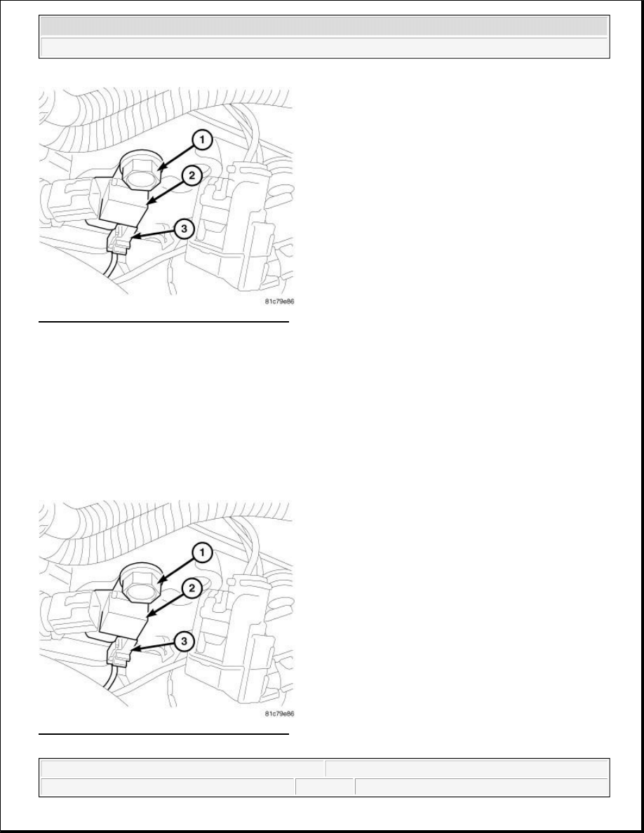
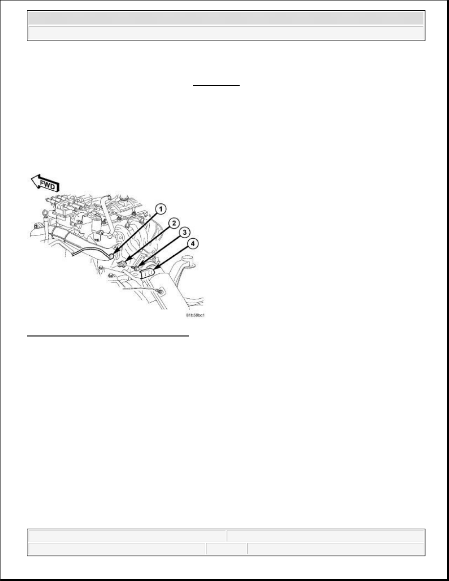
Fig. 3: Removing/Installing Ignition Capacitor
Courtesy of CHRYSLER LLC
The ignition capacitor is located on the drivers side of the engine.
1. Disconnect and isolate the negative battery cable at battery.
2. Remove electrical connector (3).
3. Remove mounting bolt (1) and ignition capacitor (2).
INSTALLATION
INSTALLATION
Fig. 4: Removing/Installing Ignition Capacitor
Courtesy of CHRYSLER LLC
2009 Chrysler Town & Country LX
2009 ENGINE Ignition Control - Service Information - Grand Caravan, Town & Country
steve
Monday, May 30, 2011 12:02:11 PM
Page 5
© 2006 Mitchell Repair Information Company, LLC.
1. Install ignition coil capacitor (2) and bolt (1).
2. Tighten bolt to 28 N.m (20.5 ft. lbs.).
3. Connect electrical connector (3).
4. Connect negative battery cable and tighten nut to 5 N.m (45 in. lbs.).
COIL, IGNITION
REMOVAL
3.3/3.8L
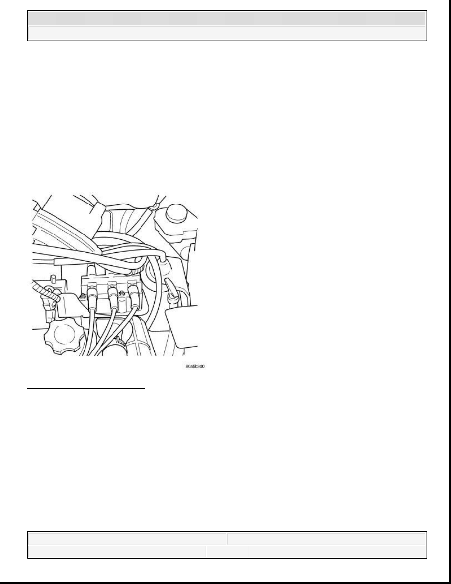
Fig. 5: Identifying Ignition Coil
Courtesy of CHRYSLER LLC
1. Disconnect and isolate the negative battery cable at battery.
2. Remove 2 bolts from the Power steering reservoir to intake manifold.
3. Loosen the lower nut for the power steering reservoir from stud on ignition coil bracket.
4. Reposition the power steering reservoir.
5. Remove the ignition cables from the ignition coil.
6. Disconnect the electrical connector from the ignition coil.
7. Remove 2 nuts from the ignition coil studs.
8. Remove ignition coil from engine.
4.0L
2009 Chrysler Town & Country LX
2009 ENGINE Ignition Control - Service Information - Grand Caravan, Town & Country
steve
Monday, May 30, 2011 12:02:11 PM
Page 6
© 2006 Mitchell Repair Information Company, LLC.
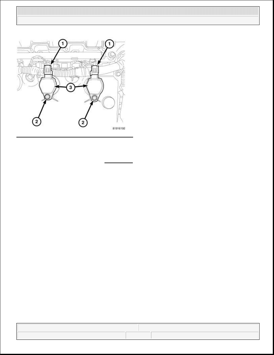
Fig. 6: Removing/Installing Ignition Coil Assembly
Courtesy of CHRYSLER LLC
1. Disconnect and isolate the negative battery cable at battery.
2. Remove intake manifold. Refer to REMOVAL .
3. Disconnect electrical connector (1) from ignition coils (3).
4. Remove mounting bolt (2).
5. Remove the ignition coil assembly (3) by turning the assembly 1/2 turn and pulling straight up in a steady
motion.
INSTALLATION
3.3/3.8L
NOTE:
Prior to removing coil, spray compressed air around coil top to make sure
no dirt drops into the spark plug tube.
2009 Chrysler Town & Country LX
2009 ENGINE Ignition Control - Service Information - Grand Caravan, Town & Country
steve
Monday, May 30, 2011 12:02:11 PM
Page 7
© 2006 Mitchell Repair Information Company, LLC.
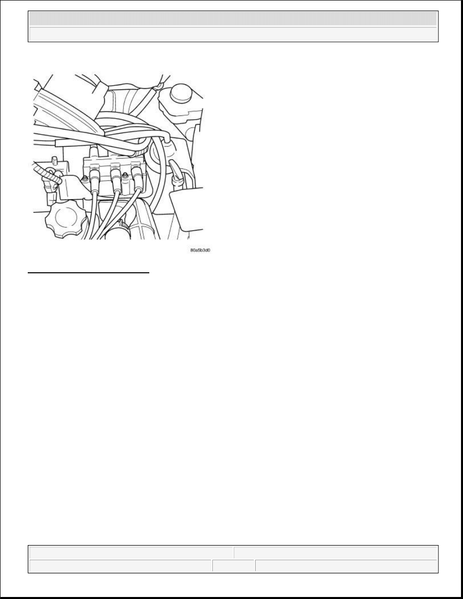
Fig. 7: Identifying Ignition Coil
Courtesy of CHRYSLER LLC
1. Install coil over studs on bracket.
2. Install 2 nuts to the ignition coil studs and tighten nuts.
3. Connect the electrical connector to the ignition coil.
4. Install the ignition cables to the ignition coil.
5. Reposition the power steering reservoir. Slide bracket over the mounting stud.
6. Install 2 bolts to the Power steering reservoir to intake manifold.
7. Tighten the lower nut to stud on ignition coil bracket.
8. Connect negative battery cable and tighten nut to 5 N.m (45 in. lbs.).
4.0L
2009 Chrysler Town & Country LX
2009 ENGINE Ignition Control - Service Information - Grand Caravan, Town & Country
steve
Monday, May 30, 2011 12:02:11 PM
Page 8
© 2006 Mitchell Repair Information Company, LLC.
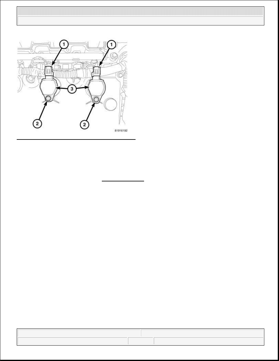
Fig. 8: Removing/Installing Ignition Coil Assembly
Courtesy of CHRYSLER LLC
1. Install ignition coil (3) and bolt (2).
2. Tighten bolt to 8 N.m (71 in. lbs.).
3. Connect the electrical connector (1) to ignition coil.
4. Install intake manifold. Refer to INSTALLATION .
5. Connect negative battery cable and tighten nut to 5 N.m (45 in. lbs.).
PLUG, GLOW
DESCRIPTION
DESCRIPTION
2009 Chrysler Town & Country LX
2009 ENGINE Ignition Control - Service Information - Grand Caravan, Town & Country
steve
Monday, May 30, 2011 12:02:11 PM
Page 9
© 2006 Mitchell Repair Information Company, LLC.
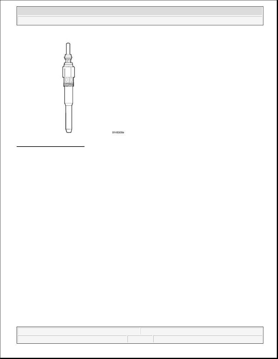
Fig. 9: Identifying Glow Plug
Courtesy of CHRYSLER LLC
Glow plugs are used to help start a cold or cool engine. The glow plugs will heat up and glow to heat the
combustion chamber of each cylinder. An individual glow plug is used for each cylinder.
OPERATION
OPERATION
CAUTION: The glow plugs operate on a 4.4-volt system. The glow plugs DO NOT
tolerate any over voltage. Full battery voltage will destroy the glow plug
immediately. DO NOT test the glow plugs with a 12V source as damage will
occur to the glow plug.
CAUTION:
Never bend, bump or knock the fast metallic glow plugs.
Fast metallic glow plugs must not be handled loose in a container.
Store, handle, and transport them only in original boxes.
If there is any doubt about the proper condition of a glow plug, do not
reuse it.
Do not clean the glow plugs with abrasive or aggressive media.
Avoid dipping the glow plug into fluids.
Read Diagnostic Trouble Codes (DTCs). If a glow plug problem is
indicated, do not start the engine.
CAUTION: Disregarding these instructions may cause severe engine damage.
2009 Chrysler Town & Country LX
2009 ENGINE Ignition Control - Service Information - Grand Caravan, Town & Country
steve
Monday, May 30, 2011 12:02:11 PM
Page 10
© 2006 Mitchell Repair Information Company, LLC.

Fig. 10: Identifying Glow Plug
Courtesy of CHRYSLER LLC
The Engine Control Module (ECM) monitors various engine sensors. When the ignition key is turned to the ON
position, the ECM sends a signal to the glow plug module (relay) to turn on, and cycle, the glow plugs for a pre-
determined amount of time, plus illuminate the glow plug light in the instrument panel. Once activated, the
element inside of the core of the glow plug begins to glow. Each glow plug draws approximately 8 amps, for a
total system amperage of 32 amps at 22° C (72° F) ambient temperature. If there is a fault with the glow plug
system, the ECM will store a fault code.
DIAGNOSIS AND TESTING
GLOW PLUGS
1. Measure the electrical resistance of each glow plug while it is still installed in the cylinder head.
Resistance should be less than 0.8ohms between the electrical connector point on the glow plug and the
cylinder head. The ground contact on the DVOM must be as close as possible to the point where the glow
plug contacts the cylinder head to avoid erratic resistance measurements.
2. If the resistance is out of tolerance, remove the glow plug from the cylinder head and check the resistance
again.
3. Use the actuator test function of the scan tool to test the glow plug module and glow plug lamp. The glow
plug module's on-board diagnostic tests will automatically check the electrical condition of the entire
CAUTION: The glow plugs operate on a 4.4-volt system. DO NOT test the glow plugs
with a 12 V source as damage will occur to the glow plug(s).
CAUTION: DO NOT attempt to start the engine until the glow plug system tests
correctly.
2009 Chrysler Town & Country LX
2009 ENGINE Ignition Control - Service Information - Grand Caravan, Town & Country
steve
Monday, May 30, 2011 12:02:11 PM
Page 11
© 2006 Mitchell Repair Information Company, LLC.
glow plug system.
4. After the scan tool glow plug actuator test function is complete, if MIL is OFF and no glow plug DTCs
are present, testing is complete and the engine can be started.
5. If MIL is still ON, check the harness connectors of glow plugs, repair any loose or damaged connections,
and run the glow plug actuator test again.
6. If MIL is still ON and glow plug DTCs are present, refer to the appropriate Diagnostic Information and
follow the diagnostic test(s) related to the active or stored DTCs.
REMOVAL
REMOVAL
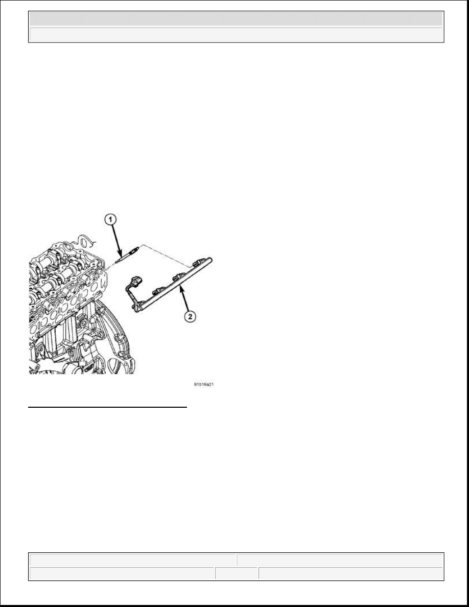
Fig. 11: Removing/Installing Glow Plugs
Courtesy of CHRYSLER LLC
The four glow plugs (1) are attached to cylinder head below fuel rail.
1. Disconnect negative battery cable.
2. Remove fuel rail and high-pressure fuel lines.
3. Disconnect glow plug wiring harness (2) at all four glow plugs (1).
2009 Chrysler Town & Country LX
2009 ENGINE Ignition Control - Service Information - Grand Caravan, Town & Country
steve
Monday, May 30, 2011 12:02:11 PM
Page 12
© 2006 Mitchell Repair Information Company, LLC.
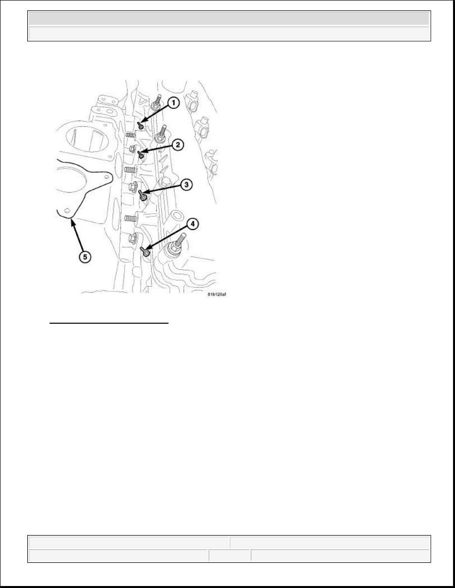
Fig. 12: Identifying Glow Plugs
Courtesy of CHRYSLER LLC
4. Use a socket to loosen glow plug(s) (1), (2), (3) or (4). After loosening, attach a flexible tool such as a
rubber hose to remove glow plug from cylinder head.
INSTALLATION
INSTALLATION
CAUTION: After plug removal, do not bend, knock, or drop the glow plugs while
handling (any mechanical impact may damage the glow plug).
2009 Chrysler Town & Country LX
2009 ENGINE Ignition Control - Service Information - Grand Caravan, Town & Country
steve
Monday, May 30, 2011 12:02:11 PM
Page 13
© 2006 Mitchell Repair Information Company, LLC.
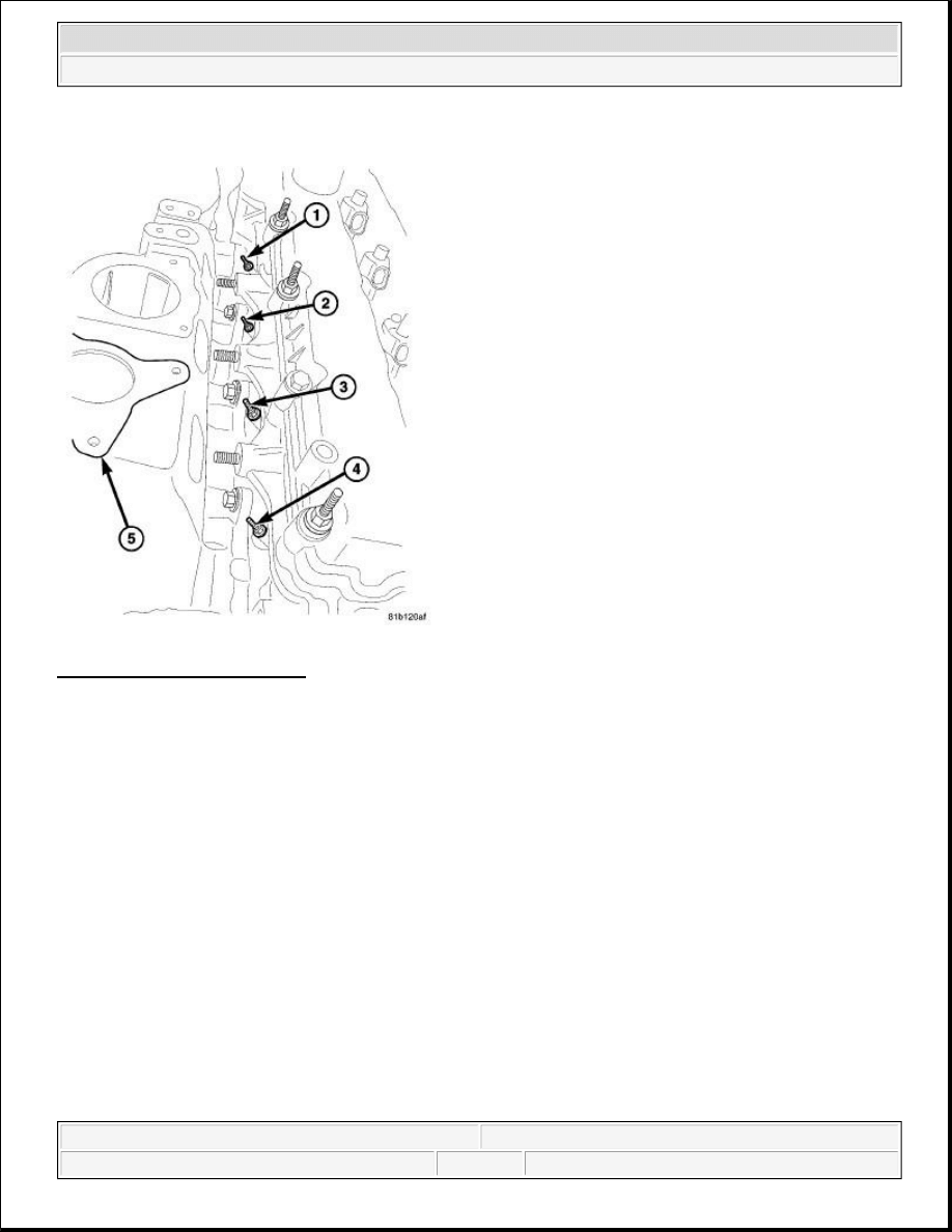
Fig. 13: Identifying Glow Plugs
Courtesy of CHRYSLER LLC
1. Apply a small amount of clean diesel oil or motor oil to glow plug threads.
2. Attach a flexible tool such as a rubber hose to install glow plug into cylinder head. Tighten each plug to
14 N.m (10 ft. lbs.) (124 in. lbs.).
2009 Chrysler Town & Country LX
2009 ENGINE Ignition Control - Service Information - Grand Caravan, Town & Country
steve
Monday, May 30, 2011 12:02:11 PM
Page 14
© 2006 Mitchell Repair Information Company, LLC.
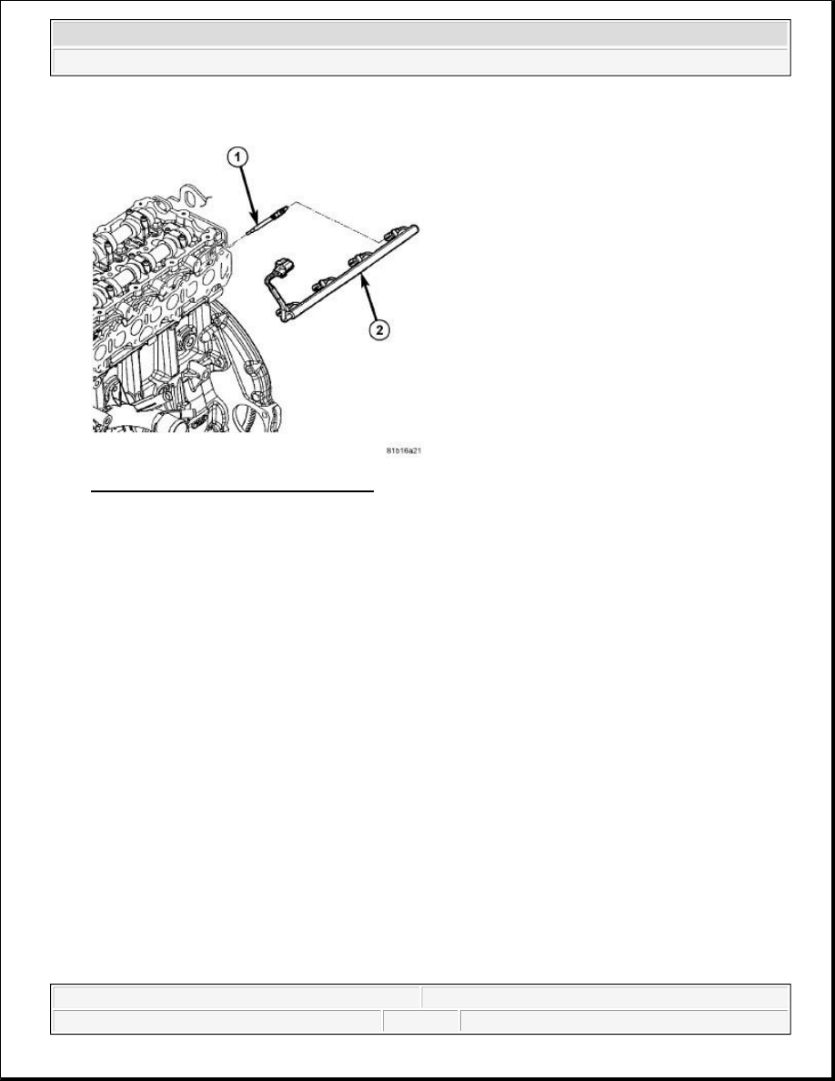
Fig. 14: Removing/Installing Glow Plugs
Courtesy of CHRYSLER LLC
3. Connect glow plug wiring harness (2) to all four glow plugs (1).
4. Install fuel rail and high-pressure fuel lines.
5. Connect negative battery cable.
RELAY, GLOW PLUG
REMOVAL
REMOVAL
2009 Chrysler Town & Country LX
2009 ENGINE Ignition Control - Service Information - Grand Caravan, Town & Country
steve
Monday, May 30, 2011 12:02:11 PM
Page 15
© 2006 Mitchell Repair Information Company, LLC.
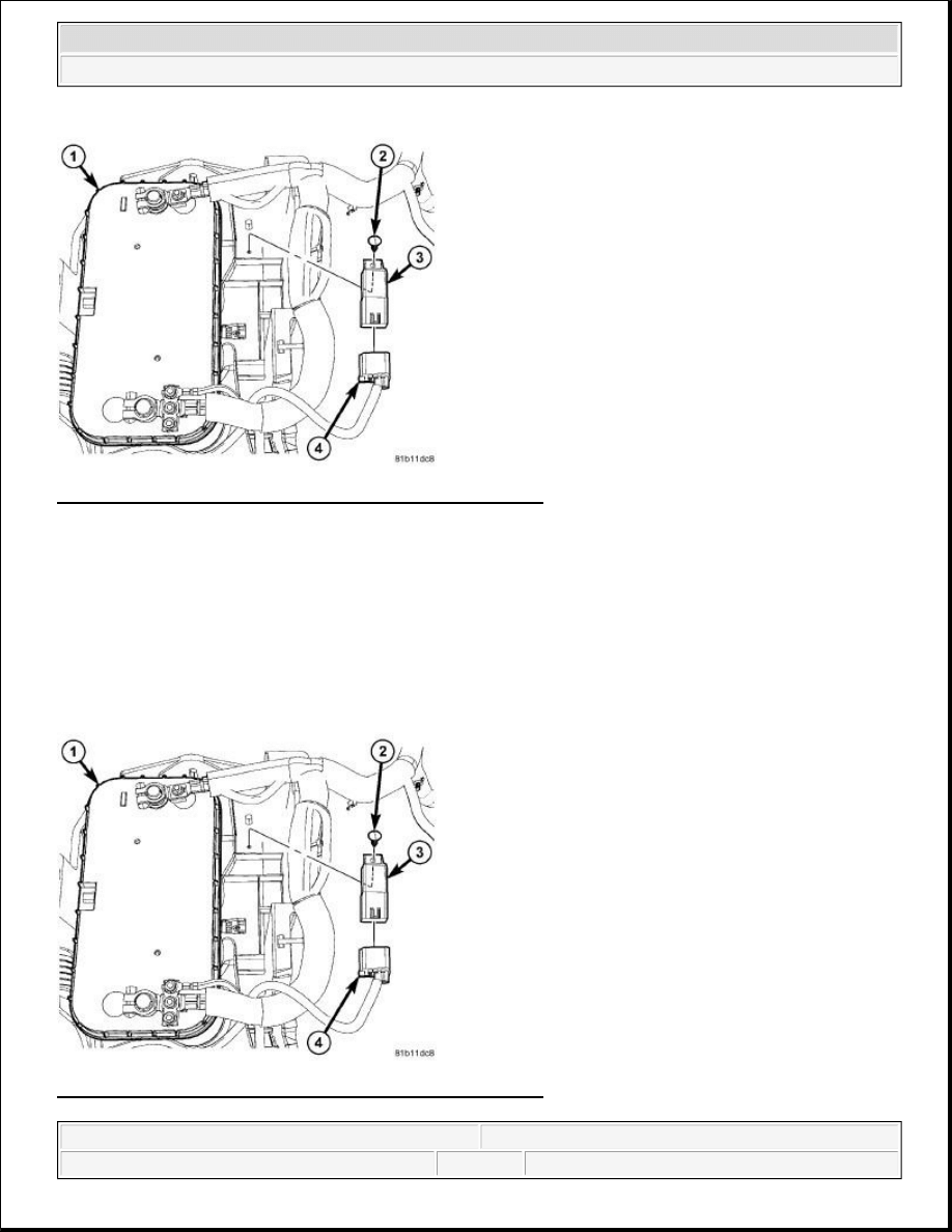
Fig. 15: Identifying Electrical Connector At Glow Plug Relay
Courtesy of CHRYSLER LLC
1. Disconnect negative battery cable.
2. Carefully pull out mounting pin (2).
3. Disconnect electrical connector (4) from relay (3).
INSTALLATION
INSTALLATION
Fig. 16: Identifying Electrical Connector At Glow Plug Relay
Courtesy of CHRYSLER LLC
2009 Chrysler Town & Country LX
2009 ENGINE Ignition Control - Service Information - Grand Caravan, Town & Country
steve
Monday, May 30, 2011 12:02:11 PM
Page 16
© 2006 Mitchell Repair Information Company, LLC.
1. Connect electrical connector (4) to relay.
2. Push mounting pin (2) through relay (3).
3. Connect negative battery cable.
SENSOR, CAMSHAFT POSITION
OPERATION
OPERATION
Fig. 17: Identifying Good Camshaft & Crankshaft Square Wave Signals For 6 Cylinder Engines
Courtesy of CHRYSLER LLC
Depiction of good camshaft and crankshaft square wave signals for 6 cylinder engines.
REMOVAL
3.3/3.8L
2009 Chrysler Town & Country LX
2009 ENGINE Ignition Control - Service Information - Grand Caravan, Town & Country
steve
Monday, May 30, 2011 12:02:11 PM
Page 17
© 2006 Mitchell Repair Information Company, LLC.
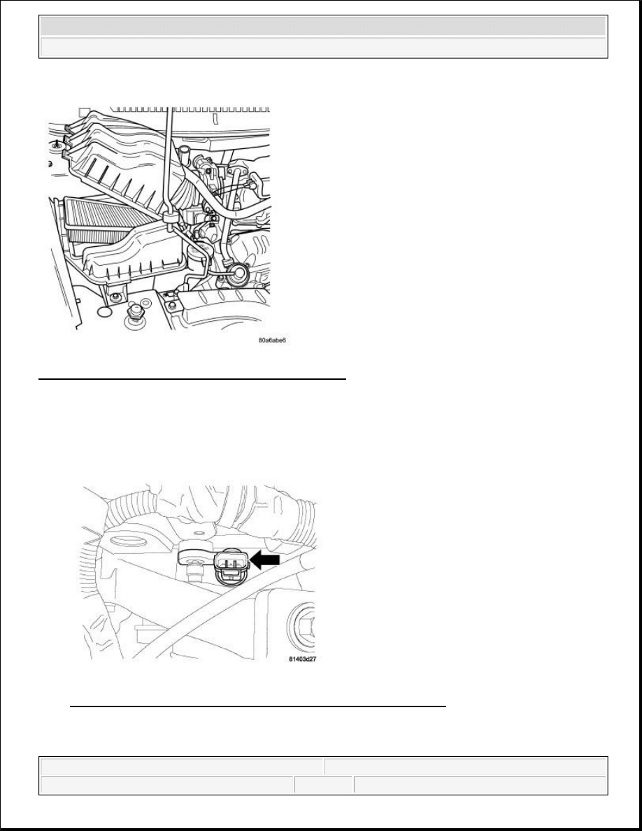
Fig. 18: Removing/Installing Air Box Cover & Inlet Tube
Courtesy of CHRYSLER LLC
1. Disconnect and isolate the negative battery cable.
2. Remove the air box cover and inlet tube.
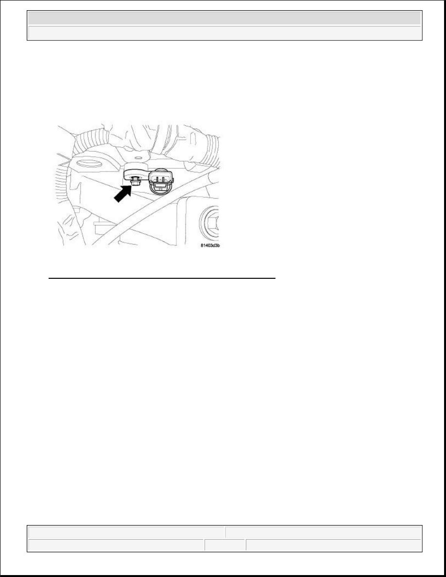
Fig. 19: Identifying Electrical Connector At Camshaft Position Sensor
Courtesy of CHRYSLER LLC
3. Disconnect the electrical connector from the camshaft position (CMP) sensor.
2009 Chrysler Town & Country LX
2009 ENGINE Ignition Control - Service Information - Grand Caravan, Town & Country
steve
Monday, May 30, 2011 12:02:11 PM
Page 18
© 2006 Mitchell Repair Information Company, LLC.
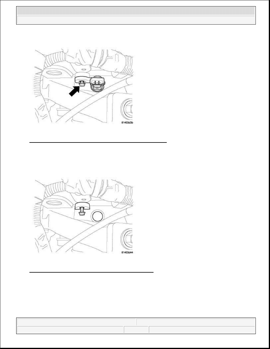
Fig. 20: Identifying Camshaft Position Sensor Retaining Bolt
Courtesy of CHRYSLER LLC
4. Loosen the CMP sensor retaining bolt.
Fig. 21: Removing/Installing Camshaft Position Sensor
Courtesy of CHRYSLER LLC
5. Pull the sensor up and out of the chain case cover. Leave the retaining bolt in place.
4.0L
2009 Chrysler Town & Country LX
2009 ENGINE Ignition Control - Service Information - Grand Caravan, Town & Country
steve
Monday, May 30, 2011 12:02:11 PM
Page 19
© 2006 Mitchell Repair Information Company, LLC.
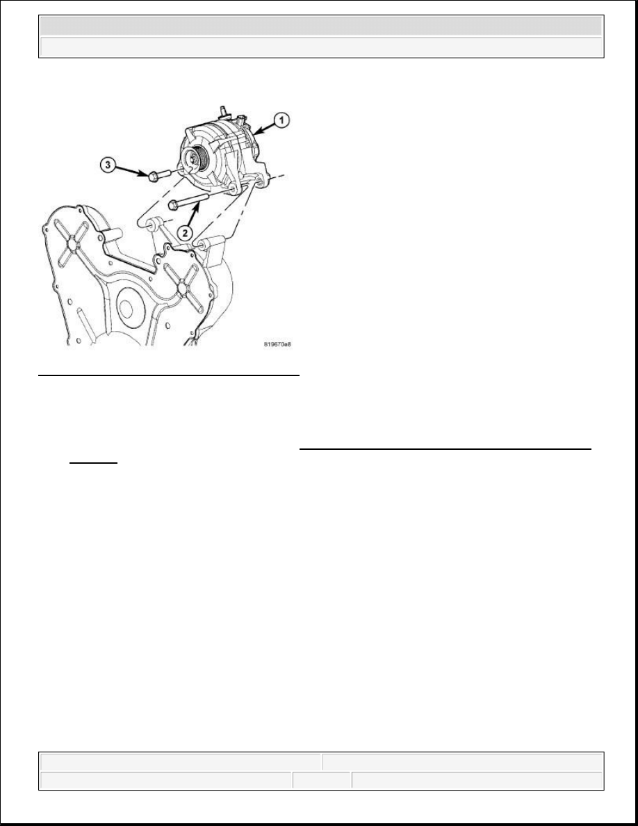
Fig. 22: Identifying Generator & Mounting Bolts
Courtesy of CHRYSLER LLC
1. Disconnect and isolate the negative battery cable at battery.
2. Remove generator mounting bolts (2), (3) and position the generator (1) aside in order to gain access to
the camshaft position (CMP) sensor. Refer to Electrical - Engine Systems/Charging/GENERATOR -
Removal .
3. Disconnect electrical connector from CMP sensor.
4. Remove bolt and CMP.
DIESEL
1. Disconnect and isolate the negative battery cable.
2009 Chrysler Town & Country LX
2009 ENGINE Ignition Control - Service Information - Grand Caravan, Town & Country
steve
Monday, May 30, 2011 12:02:11 PM
Page 20
© 2006 Mitchell Repair Information Company, LLC.
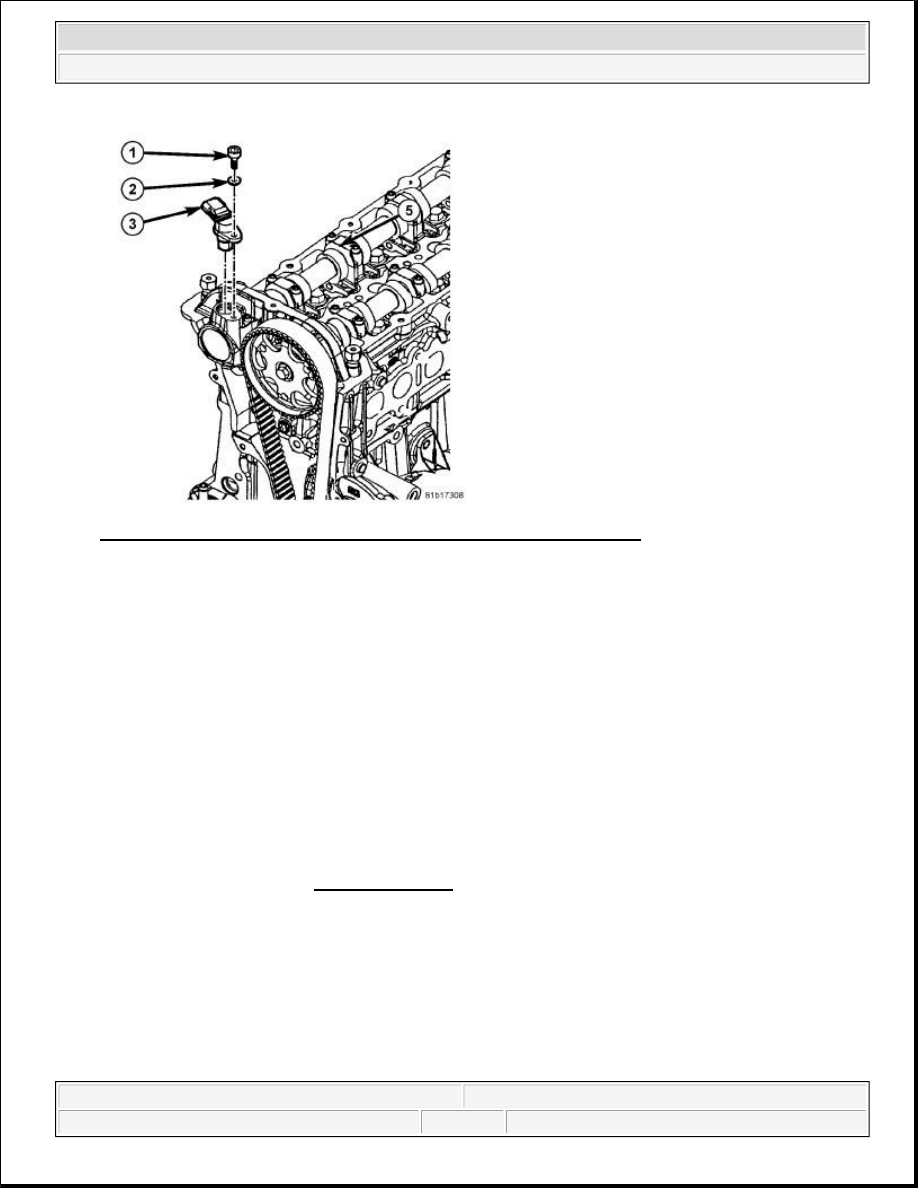
Fig. 23: Removing/Installing Camshaft Position Sensor - Diesel Engine
Courtesy of CHRYSLER LLC
The Camshaft Position Sensor (CMP) (3) is located at the front/top of the cylinder head.
2. Remove electrical connector from CMP sensor (3).
3. Clean area at base of sensor.
4. Remove sensor mounting bolt (1) and washer (2).
5. Pull sensor (3) straight up for removal.
INSTALLATION
2.8L
1. Lubricate O-ring and install sensor in cylinder head cover. Torque retaining bolt to 5.4 N.m (48 in. lbs.).
2. Connect camshaft position sensor electrical connector.
3. Install engine cover. Refer to INSTALLATION .
4. Connect negative battery cable and tighten nut to 5 N.m (45 in. lbs.).
3.3/3.8L
2009 Chrysler Town & Country LX
2009 ENGINE Ignition Control - Service Information - Grand Caravan, Town & Country
steve
Monday, May 30, 2011 12:02:11 PM
Page 21
© 2006 Mitchell Repair Information Company, LLC.
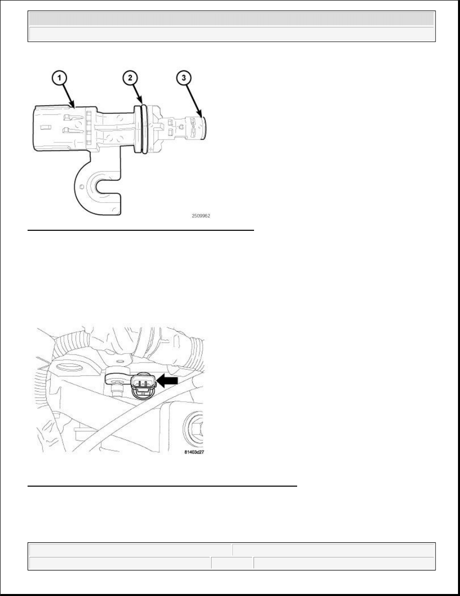
Fig. 24: Identifying Camshaft Position Sensor Components
Courtesy of CHRYSLER LLC
Fig. 25: Identifying Electrical Connector At Camshaft Position Sensor
Courtesy of CHRYSLER LLC
NOTE:
If reinstalling the sensor (1), check the sensor O-ring (2) for damage and replace
if necessary. Lubricate the O-ring with clean engine oil before installing the
sensor. Clean off the old spacer (3) on the sensor face. A NEW SPACER (3)
must be attached to the face before installation.
CAUTION: A NEW SPACER must be attached to the face of the sensor before
installation. The spacer sets the correct clearance between the sensor and
the camshaft gear. An improperly positioned sensor can result in sensor
2009 Chrysler Town & Country LX
2009 ENGINE Ignition Control - Service Information - Grand Caravan, Town & Country
steve
Monday, May 30, 2011 12:02:11 PM
Page 22
© 2006 Mitchell Repair Information Company, LLC.
1. Install the camshaft position (CMP) sensor in the chain case cover and rotate into position.
Fig. 26: Identifying Camshaft Position Sensor Retaining Bolt
Courtesy of CHRYSLER LLC
2. Push the sensor down until contact is made with the camshaft gear. While holding the sensor in this
position, install and tighten the retaining bolt to 14 N.m (125 in. lbs.).
3. Connect and lock the electrical connector to the CMP sensor.
damage, a faulty signal or no signal at all.
2009 Chrysler Town & Country LX
2009 ENGINE Ignition Control - Service Information - Grand Caravan, Town & Country
steve
Monday, May 30, 2011 12:02:11 PM
Page 23
© 2006 Mitchell Repair Information Company, LLC.
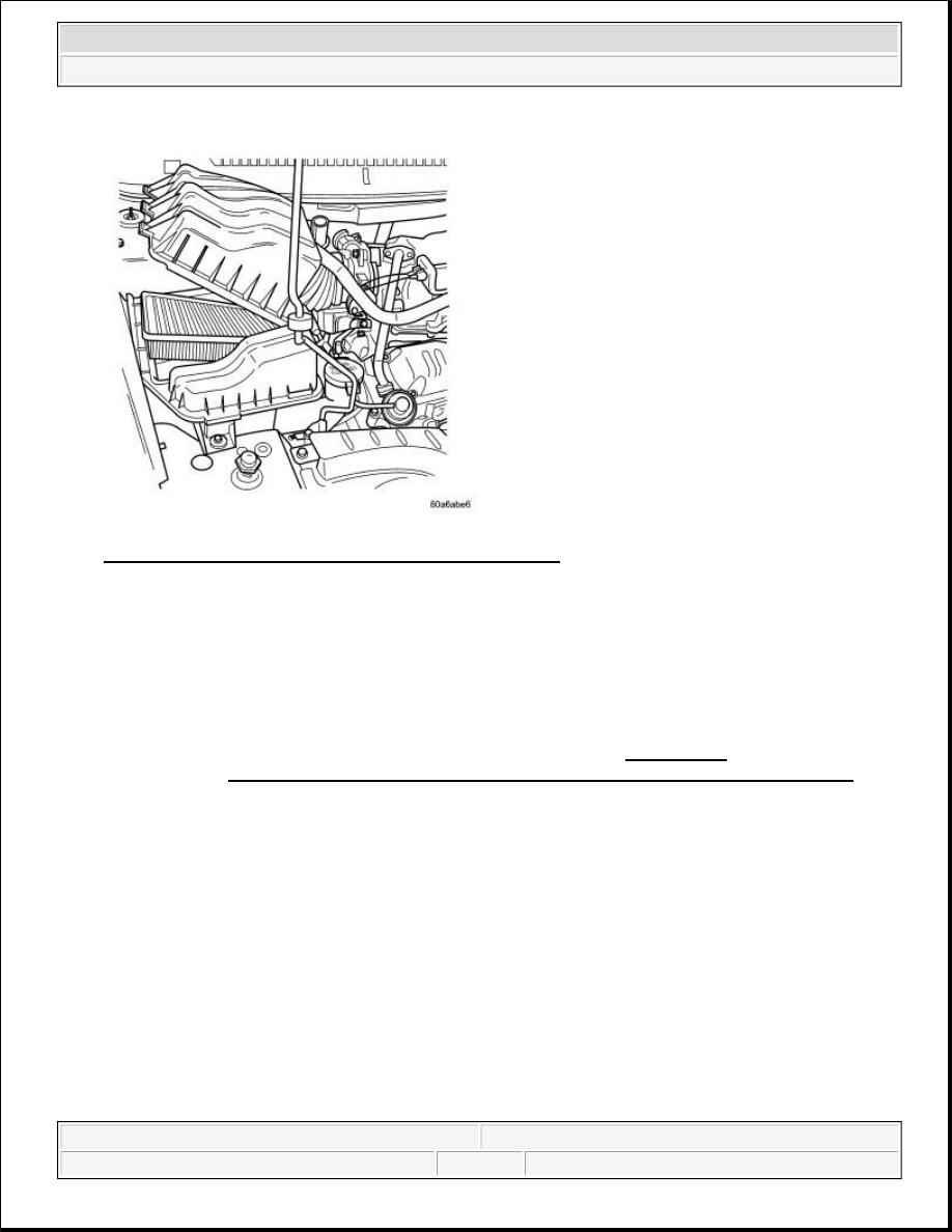
Fig. 27: Removing/Installing Air Box Cover & Inlet Tube
Courtesy of CHRYSLER LLC
4. Install the air box cover and inlet tube.
5. Connect the negative battery cable and tighten nut to 5 N.m (45 in. lbs.).
4.0L
NOTE:
The Cam/Crank Variation Relearn procedure must be performed using a
scan tool anytime there has been a repair/replacement made to a
powertrain system, for example: flywheel, valvetrain, camshaft and/or
crankshaft sensors or components. Refer to DTC-Based
Diagnostics/MODULE, Powertrain Control (PCM) - Standard Procedure .
2009 Chrysler Town & Country LX
2009 ENGINE Ignition Control - Service Information - Grand Caravan, Town & Country
steve
Monday, May 30, 2011 12:02:11 PM
Page 24
© 2006 Mitchell Repair Information Company, LLC.
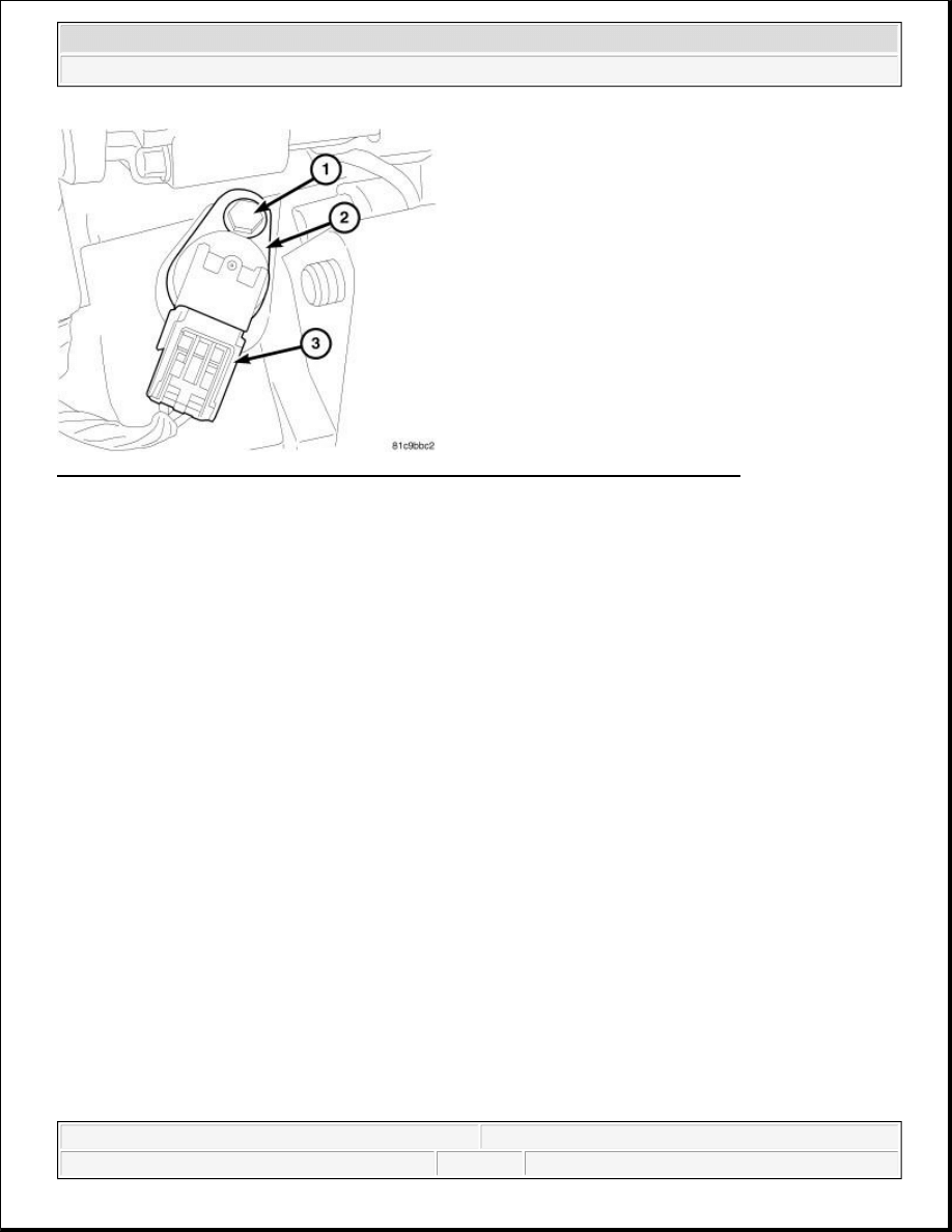
Fig. 28: Identifying Camshaft Position Sensor, Electrical Connector, & Retaining Bolt
Courtesy of CHRYSLER LLC
1. Push the CMP sensor (2) into the timing belt cover with a twisting motion until fully seated.
2. While holding the sensor (2) in this position, install and tighten the retaining bolt (1) to 12 N.m (106 in.
lbs.).
3. Connect and lock the electrical connector (3) to the CMP sensor (2).
CAUTION: Install camshaft position (CMP) sensor utilizing twisting motion. Make sure
CMP sensor is fully seated. Do not drive CMP sensor into the bore with
mounting screw. This may cause CMP sensor to be incorrectly seated
causing a faulty signal or no signal at all.
NOTE:
If reinstalling the sensor, check the sensor O-ring for damage and replace if
necessary. Lubricate the O-ring with clean engine oil before installing the
sensor.
2009 Chrysler Town & Country LX
2009 ENGINE Ignition Control - Service Information - Grand Caravan, Town & Country
steve
Monday, May 30, 2011 12:02:11 PM
Page 25
© 2006 Mitchell Repair Information Company, LLC.
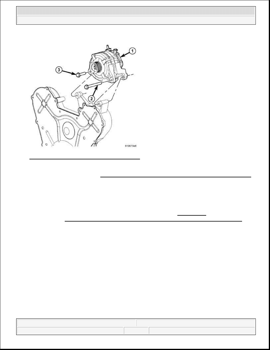
Fig. 29: Identifying Generator & Mounting Bolts
Courtesy of CHRYSLER LLC
4. Install the generator (1). Refer to Electrical - Engine Systems/Charging/GENERATOR - Installation .
5. Connect the negative battery cable and tighten nut to 5 N.m (45 in. lbs.).
DIESEL
NOTE:
The Cam/Crank Variation Relearn procedure must be performed using a
scan tool anytime there has been a repair/replacement made to a
powertrain system, for example: flywheel, valvetrain, camshaft and/or
crankshaft sensors or components. Refer to DTC-Based
Diagnostics/MODULE, Powertrain Control (PCM) - Standard Procedure .
2009 Chrysler Town & Country LX
2009 ENGINE Ignition Control - Service Information - Grand Caravan, Town & Country
steve
Monday, May 30, 2011 12:02:11 PM
Page 26
© 2006 Mitchell Repair Information Company, LLC.
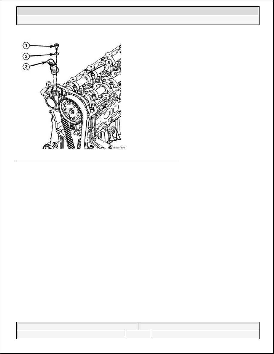
Fig. 30: Removing/Installing Camshaft Position Sensor - Diesel Engine
Courtesy of CHRYSLER LLC
1. Position CMP sensor (3) into mounting hole.
2. Install sensor mounting bolt (1) and washer (2). Tighten bolt to 11 Nm ( 8 ft. lbs.).
3. Connect electrical connector to CMP sensor (3).
4. Reconnect the negative battery cable.
SENSOR, KNOCK
REMOVAL
3.3/3.8L
2009 Chrysler Town & Country LX
2009 ENGINE Ignition Control - Service Information - Grand Caravan, Town & Country
steve
Monday, May 30, 2011 12:02:11 PM
Page 27
© 2006 Mitchell Repair Information Company, LLC.
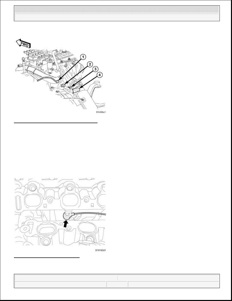
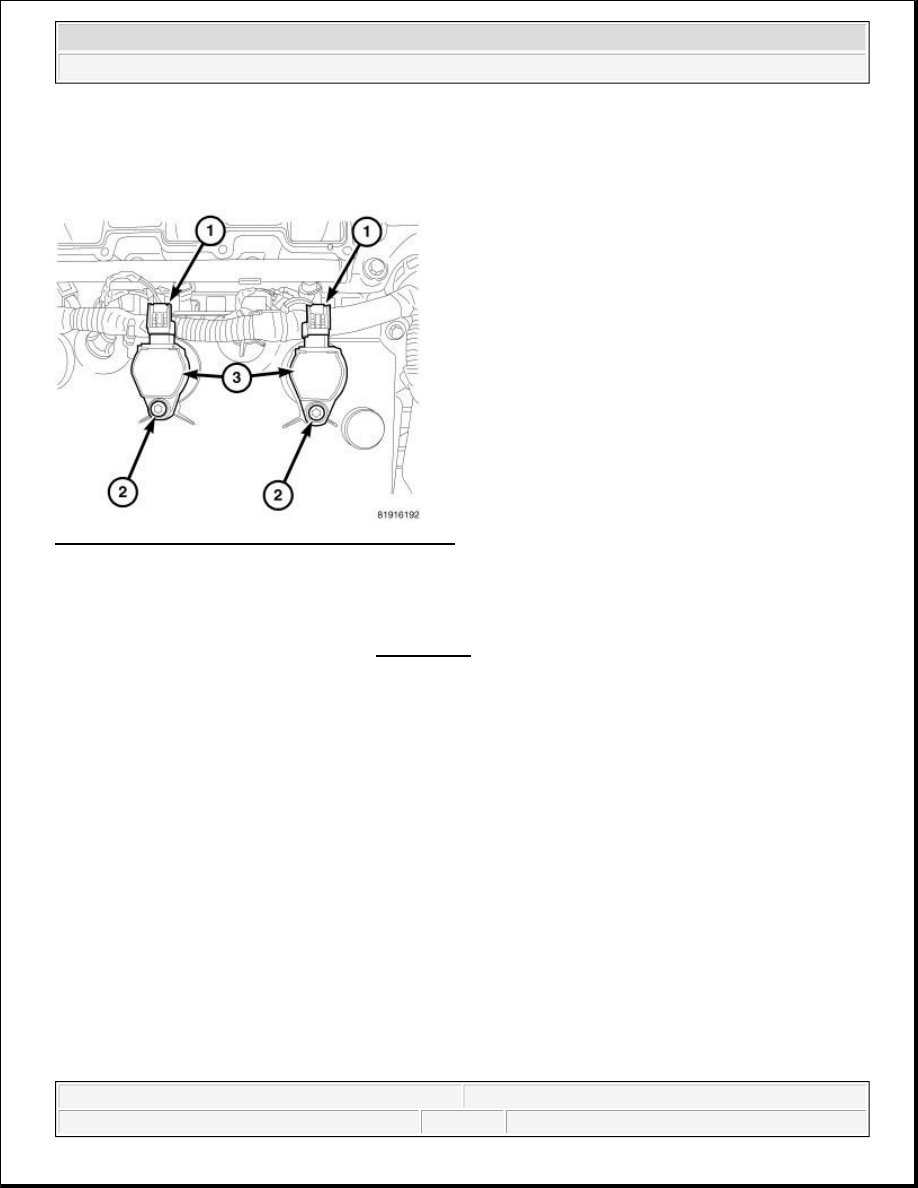
Fig. 31: Removing/Installing Knock Sensor
Courtesy of CHRYSLER LLC
1. Disconnect and isolate the negative battery cable at battery.
2. Remove knock sensor cover (4).
3. Disconnect electrical connector (1) from knock sensor (2).
4. Remove bolt (3) and knock sensor (2) from engine.
4.0L
Fig. 32: Identifying Knock Sensor
Courtesy of CHRYSLER LLC
1. Disconnect and isolate the negative battery cable at battery.
2009 Chrysler Town & Country LX
2009 ENGINE Ignition Control - Service Information - Grand Caravan, Town & Country
steve
Monday, May 30, 2011 12:02:11 PM
Page 28
© 2006 Mitchell Repair Information Company, LLC.
2. Remove engine cover.
3. Remove upper intake manifold. Refer to REMOVAL .
4. Disconnect electrical connector.
5. Remove knock sensor.
INSTALLATION
3.3/3.8L
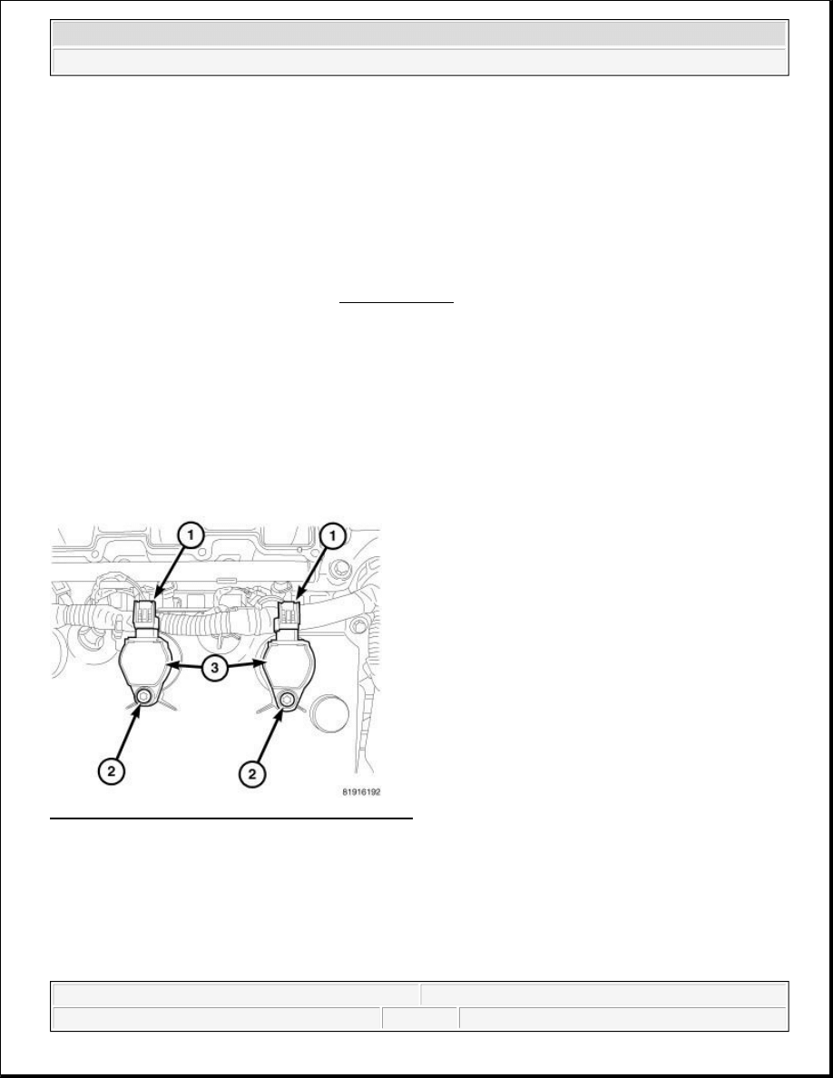
Fig. 33: Removing/Installing Knock Sensor
Courtesy of CHRYSLER LLC
1. Install knock sensor (2) and bolt (3) to engine and tighten to 20 N.m (15 ft. lbs.).
2. Connect electrical connector (1) to knock sensor (2).
3. Install knock sensor cover (4).
4. Connect the negative battery cable and tighten nut to 5 N.m (45 in. lbs.).
4.0L
CAUTION: Torque the knock sensor to correct specification. Over or under tightening
effects knock sensor performance, possibly causing improper spark
control and damage to the sensor.
2009 Chrysler Town & Country LX
2009 ENGINE Ignition Control - Service Information - Grand Caravan, Town & Country
steve
Monday, May 30, 2011 12:02:11 PM
Page 29
© 2006 Mitchell Repair Information Company, LLC.
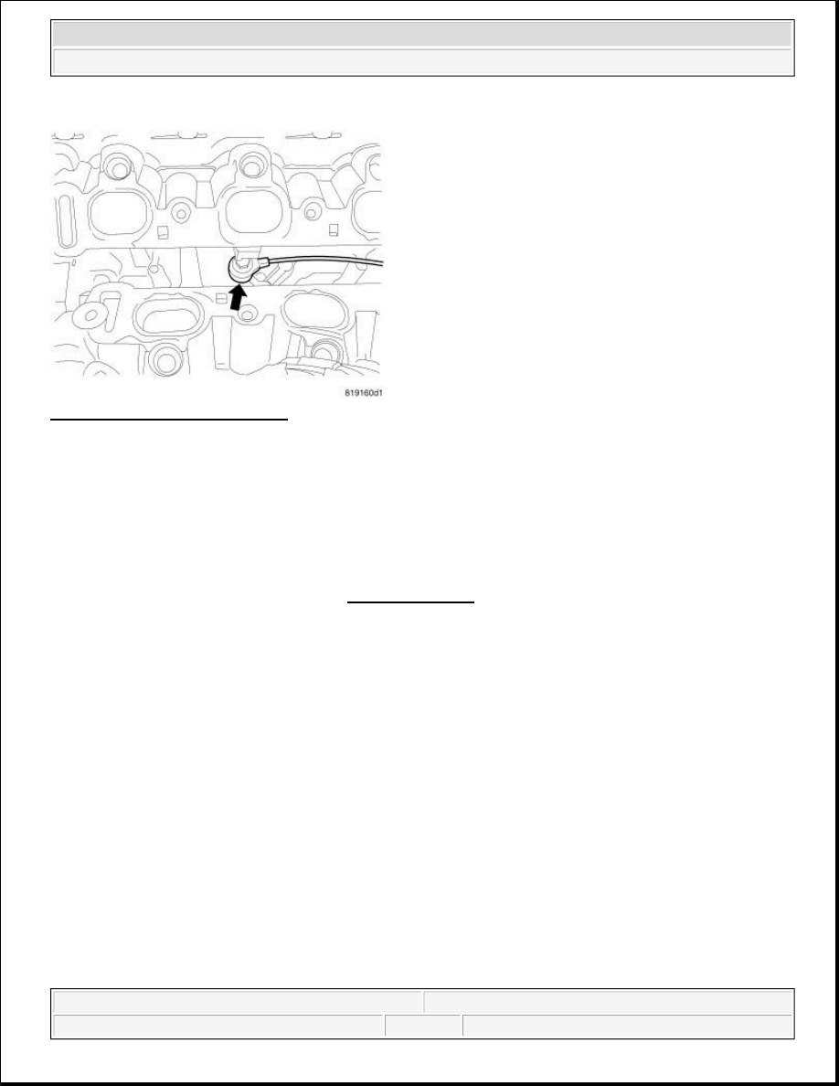
Fig. 34: Identifying Knock Sensor
Courtesy of CHRYSLER LLC
1. Install knock sensor and bolt. Tighten bolt to 20 N.m (15 ft. lbs.).
2. Route knock sensor wire in the proper location.
3. Install upper intake manifold. Refer to INSTALLATION .
4. Connect electrical connector.
5. Connect the negative battery cable and tighten nut to 5 N.m (45 in. lbs.).
SPARK PLUG
REMOVAL
3.3/3.8L
When replacing the spark plugs and spark plug cables, route the cables correctly and secure them in the
appropriate retainers. Failure to route the cables properly can cause the radio to reproduce ignition noise, cross
ignition of the spark plugs or short circuit the cables to ground.
Always remove cables by grasping at the boot, rotating the boot 1/2 turn, and pulling straight back in a steady
motion.
1. Prior to removing the spark plug, spray compressed air around the spark plug hole and the area around the
spark plug.
2. Remove the spark plug using a quality socket with a foam insert.
CAUTION: Torque the knock sensor to correct specification. Over or under tightening
effects knock sensor performance, possibly causing improper spark
control and damage to the sensor.
2009 Chrysler Town & Country LX
2009 ENGINE Ignition Control - Service Information - Grand Caravan, Town & Country
steve
Monday, May 30, 2011 12:02:11 PM
Page 30
© 2006 Mitchell Repair Information Company, LLC.
3. Inspect the spark plug condition.
4.0L
Fig. 35: Removing/Installing Ignition Coil Assembly
Courtesy of CHRYSLER LLC
1. Disconnect and isolate the negative battery cable.
2. Remove engine cover.
3. Remove the intake manifold. Refer to REMOVAL .
4. Disconnect electrical connectors (1).
5. Remove mounting bolt (2).
6. Remove the ignition coil assembly (3) by turning the assembly 1/2 turn and pulling straight up in a steady
motion.
7. Remove the spark plug using a quality socket with a foam insert.
INSTALLATION
3.3/3.8L
NOTE:
Prior to removing coil, spray compressed air around coil top to make sure
no debris drops into the spark plug tube.
NOTE:
Prior to loosening the spark plug, use compressed air to blow out any
debris that might be in the spark plug tube.
NOTE:
When replacing spark plugs and ignition cables, route cables correctly and
2009 Chrysler Town & Country LX
2009 ENGINE Ignition Control - Service Information - Grand Caravan, Town & Country
steve
Monday, May 30, 2011 12:02:11 PM
Page 31
© 2006 Mitchell Repair Information Company, LLC.
1. Apply a small amount of anti-seize to threads of each spark plug.
2. Check and adjust spark plug gap. See SPARK PLUGS.
3. Install spark plug and tighten to 17.5 N.m (13 ft. lbs.).
4. Install ignition cables over spark plugs. An audible click noise can be heard and felt when the ignition
cable is properly attached to spark plug.
4.0L
Fig. 36: Removing/Installing Ignition Coil Assembly
Courtesy of CHRYSLER LLC
1. Tighten spark plugs to 27 N.m (20 ft. lbs.).
2. Install ignition coil (3) and bolt (2).
secure in appropriate retainers. Failure to route ignition cables properly can
cause the radio to reproduce noise, cross ignition of the spark plugs or short
circuit the cables to ground.
CAUTION: Do not over apply anti-seize compound. Only use enough to lightly coat
threads on the spark plug.
CAUTION: Start each spark plug by hand to avoid cross threading and plug
damage, use a quality socket with a rubber insert and start each
spark plug into the cylinder head by hand.
CAUTION: Start each spark plug by hand to avoid cross threading and plug damage,
use a quality socket with a rubber insert and start each spark plug into the
cylinder head by hand.
2009 Chrysler Town & Country LX
2009 ENGINE Ignition Control - Service Information - Grand Caravan, Town & Country
steve
Monday, May 30, 2011 12:02:11 PM
Page 32
© 2006 Mitchell Repair Information Company, LLC.

3. Tighten bolt to 8 N.m (71 in. lbs.).
4. Connect electrical connector (1) to ignition coil (3).
5. Install intake manifold. Refer to INSTALLATION .
6. Install engine cover.
7. Connect negative battery cable and tighten nut to 5 N.m (45 in. lbs.).
SWITCH, IGNITION
DESCRIPTION
DESCRIPTION
This vehicle is equipped with a Wireless Ignition Node (WIN). The WIN, along with the FOB with Integrated
Key (FOBIK) are the primary components of the keyless ignition system. The only visible component of the
WIN is the ignition switch located on the face of the instrument panel just to the inboard side of the steering
column. The remainder of the WIN including its mounting provisions and electrical connections are concealed
within the instrument panel.
In addition to replacing a conventional keyed ignition switch, the WIN is an integrated electronic receiver that
serves as the base station in the vehicle. It communicates with other electronic modules in the vehicle over the
Controller Area Network (CAN) data bus.
The WIN interfaces with the Remote Keyless Entry (RKE) FOBIK and the Tire Pressure Monitor (TPM)
sensors (if equipped) using Radio Frequency (RF) communication, with the Sentry Key Immobilizer System
(SKIS) transponder within the FOBIK using Low Frequency (LF) RF communication.
The WIN cannot be adjusted or repaired, but is flash update capable. If ineffective or damaged the entire WIN
must be replaced. Refer to Electrical - Electronic Control Modules/Electronic Control
Modules/RECEIVER, Wireless Ignition Node - Removal .
2009 Chrysler Town & Country LX
2009 ENGINE Ignition Control - Service Information - Grand Caravan, Town & Country
steve
Monday, May 30, 2011 12:02:11 PM
Page 33
© 2006 Mitchell Repair Information Company, LLC.
Wyszukiwarka
Podobne podstrony:
Damage Control Plan
14 Controllingid 15298 ppt
Controlling w przedsiębiorstwie
overview simatic controllers 04 2007 en plc
Control System Toolbox
control el heater pl
instrumenty Controllingu - praca zaliczeniowa (7 str), Zarządzanie(1)
rachunkowosc zarzadcza i controlling w 7
~$O Fire Control Symbols Regulations
Controlling ćw 14 10 27
controlling finansowy wykład 2 & 11 2011
10 Emission control system
02 ZELIO CONTROL CATALOGUE
Climate Control
(1 1)Fully Digital, Vector Controlled Pwm Vsi Fed Ac Drives With An Inverter Dead Time Compensation
12 Werntges controling KNX from Linux and USB
Ebsco Gross The cognitive control of emotio
Dynapower Model 66 & 99 Modular Controls Parts
M31f1 Engine Controls 1 54
więcej podobnych podstron