
INSTITUT FOR
M
EKANIK
,
E
NERGI
OG
K
ONSTRUKTION
Sektionen for Konstruktion og Produktudvikling
DANMARKS TEKNISKE UNIVERSITET
MEK
Georg K. Christensen
Design of a Pro/Engineer motion skeleton model
for a Briggs & Stratton petrol engine
(ProEngineer Wildfire 2.0)
The purpose of this exercise is to introduce the concept of skeleton models used in
ProEngineer. The skeleton models are useful for the creation of assemblies without too
many assembly interdependencies e.g. constraints. In addition - as will be shown by this
exercise, the skeletons are useful in creating simple forms of ”animation” of the models. A
skeleton in ProEngineer is a frame for the rest of the model. This skeleton can be used for
creation of motion, but also as a means for control of space-allocation during product
design. Examples are products with mechanically integrated, but distinct subsystems. In
a mobile phone the visual appearance or shell can be divided in subspaces for display,
keyboard, circuit board, batteries etc.
During the exercise an assembly consisting of a skeleton model and a crankshaft
mechanism is created. The mechanism is animated and a first element the mechanism ,
the piston is assembled. The remainder of the assembly process is left to the user of this
note.
Step 1:
Creation of the
Skeleton part
2 af 7
jan. 05
A skeleton part must be created as an entity
within an assembly. Therefore start creating a
new assembly KRANK_W.ASM. Accept to insert
the default coordinate system.
The skeleton part is now created within the
assembly sing: Insert/Component/Create/Skele –
ton-Model/Name: KRANK_W_SKEL.PRT (default)
Accept the coordinate system
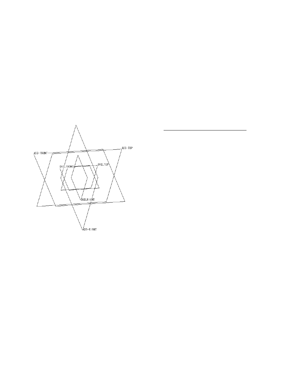
*. In the model tree redefine
however the names of the coordinate planes to:
SKEL
right
,SKEL
top, and
SKEL
front. Following
this, the screen should look like fig. 1.
Notice that the
Krank_w_skel.prt
now has taken
the top position in the model tree. It is only
possible to have one skeleton part in each
assembly (subassembly) and its position is at the top.
Fig. 1
In order to achieve correctness during the modelling of the skeleton part we must be sure
not to use assembly datum planes as references. This will be achieved here by opening the
skeleton model just as any other part. The features created subsequently will only refer
to items of the
KRANK_W_SKEL.PRT
. Do as follows: Open KRANK_W_SKEL.PRT by right
klicking on the part in the model tree - then select Open. In fig. 2 and fig. 3 the results of
the operations on the model tree is shown. Fig. 2 shows the tree before opening
KRANK_W_SKEL.PRT
and fig. 3 show the tree following the Open command.
*Unix: Browse to exercise1/ and select: mmns_part_solid.prt

3 af 7
jan. 05
STEP 2: Building the skeleton model
Fig. 4
Fig. 2
Fig. 3
Step 2.1 Insert a datum axis along the
intersection of
SKELtop
and
SKEL
front.
Step 2.2. A datum circle corresponding to the
movement of the crankshaft bearing is created
using the Sketched Datum Curve tool:
Use
SKELri
ght
as the sketching plane and the newly
created datum axis as the centre.
Step 2.3 Create a datum curve corresponding to
the crankshaft arm and a curve corresponding
to the connecting rod
. (select
). As
referen-ces use only the axis, the datum circle
and the piston movement plane (normally:
SKELfront
).
The model should now look like fig. 4. Arrange that
dimensions corresponding to the measures d1
and d2 are present. The angle d2 is used in the
following to create the movement corresponding
to the turning of the crankshaft. Try if the
skeleton can move by modifying the value d2
(regenerate). Save the model.
Step 3: Creation of motion using Relations
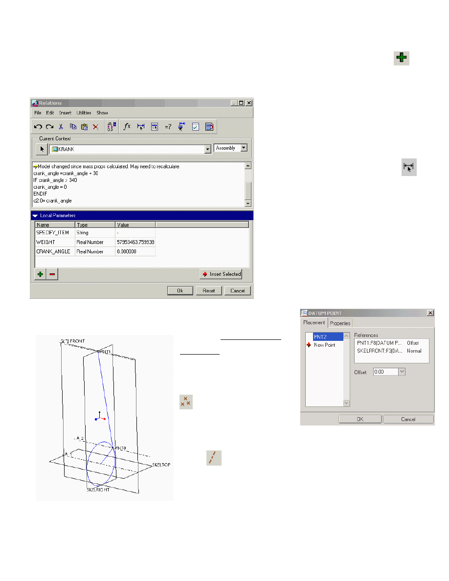
Programming a ProEngineer Relation containing the parameter d2 now creates a
controlled movement. D2 represents the crank angle. Before the relations can be progra-
med a new variable crank_angle is defined. Use Tools/Relations/Local Parameters/
Type: crank_angle. See fig. 5.
The Relations are typed in the text area above. Insert the program lines as shown in fig. 5.
The variable d2:0 used here is an
internal variable name given to the
crankshaft angle. The actual variable
name for the crankshaft angle in your
exercise may vary from this.
Make
ProEngineer show the variable names by typing:
followed by a click at the connecting rod in the
Graphics window.
Finally click at the actual variable for
the crankshaft angle
* (in this note: d2:0).
Fig. 5
The relations will be recalculated each
time the model is regenerated.
Therefore the crankshaft angle is
incremented by 30° per regeneration.
Try to regenerate in order to examine if
the programmed relations are making
the crankshaft turn as expected.
4 af 7
jan. 05
STEP 4: Finishing the
skeleton
4.1 Create datum points at
the ends of the connecting
rod (on the vertex using:
).
4.2 Create datum axis
through these points
using:
and the datum axis toolbox (fig. 6b)
Fig. 6a
Fig. 6b
*UNIX: to find the internal variable name you have to select
the “connection” sketch2 from the model tree, RMB and
EDIT. Remember the variable name and type it into
relations.
In this way a couple of movable datum axis are created. In fig. 6a
the axis are A2, and A3
.
SKELfront is not moving but used as
reference for the piston movement. Once again check if the
relations work properly. The skeleton model is now ready for use.
5 af 7
jan. 05
Keystrokes and mouse-clicks that are used often can be ”automated” by the use
of Mapkeys. This is done as follows: Utilities /Mapkeys/New (delete: KeySequence).
Define a new KeySequence, preferably by selecting a new one. Here ra could be used
as an abbreviation of: regenerate automatic. Then type Record and execute the
number of mouse-clicks or keyboard actions you want to record. Type:
Stop/OK/Save to end recording. Test the function.
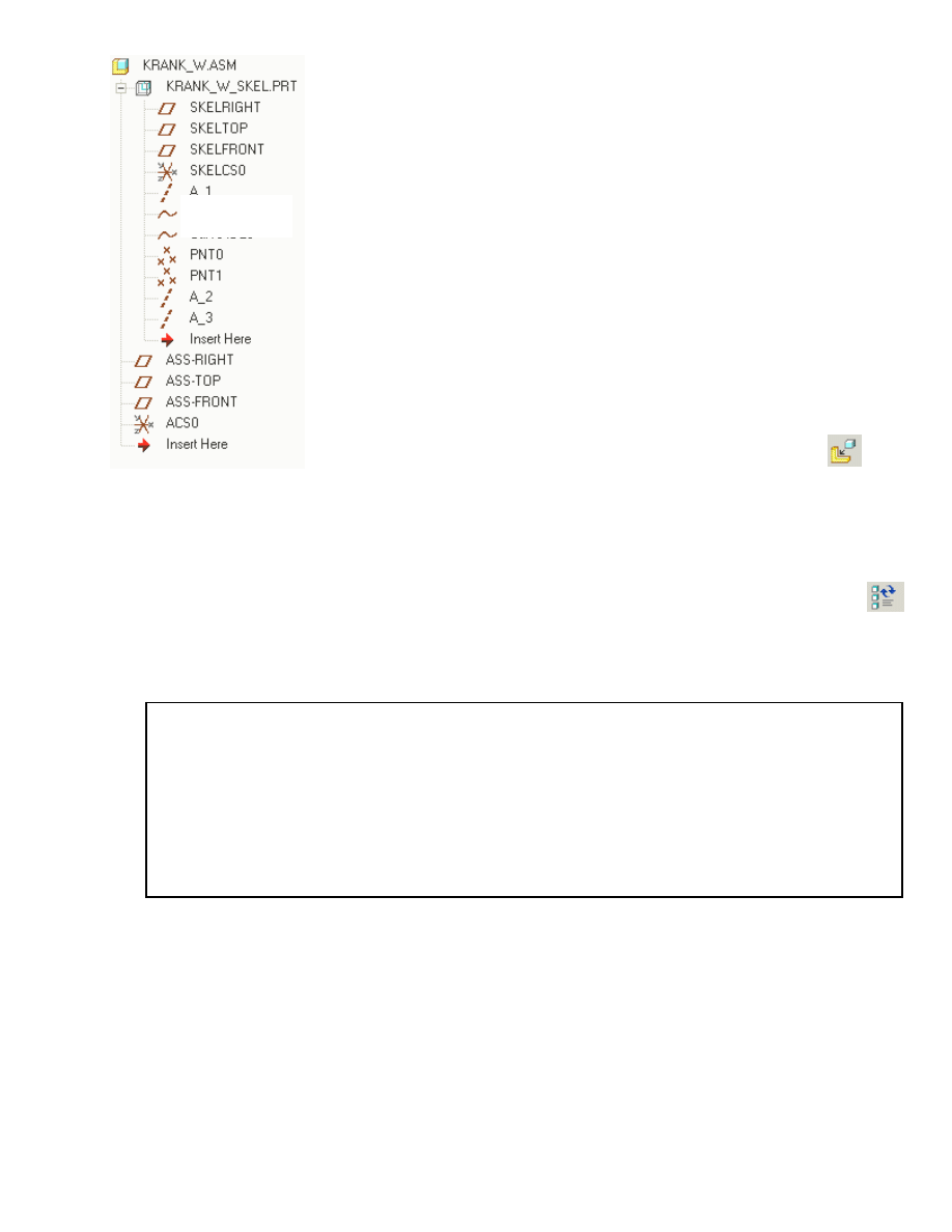
If required at a later state the skeleton model can be modified or
extended in the same manner as parts in an assembly can be
modified e.g. by opening the part. Save and close the window. With
KRANK_W.ASM open notice that KRANK_W_SKEL.PRT now has
become an extended branch of the model tree .The Model tree
should look like fig. 7.
STEP 5: The assembly process continues by assembling
the mechanism parts
The assembly KRANK_W.ASM is now ready to accept the
mechanism parts. The parts are assembled using:
/Add
component to the assembly. During this process only references
that are part of the skeleton model should be used. Examples are
PN1!,PNT2, A1, A2, A3 and SKELRIGHT. Following the above
mentioned procedure the assembled parts will only refer to the movable skeleton and they
can therefore be easily replaced at a later stage. The animation is here done by:
Regenerate/ Automatic.
Fig. 7
SKETCH 1
SKETCH 2

In figure 8 the result of the assembly process for the piston is
shown. By following the outlined procedure none of the assembled
components will have references to each other. Exceptions here are
the two bolts for assembling the connection rod. All others refer
only to the skeleton. It is easy now to replace an old connection rod
with a new, because the rest of the assembly is not directly involved.
6 af 7
jan. 05
The drawback of the method is that no immediate verification of
the fitting of the involved parts is done. As an example: does the
piston pin actually fit the holes in the piston ? And in the
connecting rod ?
Notice that in this way we can actually “assemble” a too thick pin in
a too small hole. It is therefore necessary to make a number of
assembly drawings in order to check for interference and other
types of mismatch. ProEngineer offers here some good help in:
Fig. 8
Analyse/Model analysis/Global Interference/Compute and related functions.

7 af 7
jan. 05
Document Outline
Wyszukiwarka
Podobne podstrony:
Eurocode 6 Part 1 2 1996 2005 Design of Masonry Structures General Rules Structural Fire Design
Eurocode 3 Part 1 9 2005 UK NA Design of Steel Structures Fatigue
Eurocode 3 Part 1 9 2005 Design of Steel Structures Fatigue
Eurocode 8 Part 6 1998 2005 Design of Structures for Earthquake Resistance Towers, Masts and Ch
Eurocode 3 Part 1 11 2005 UK NA Design of Steel Structures Design of Structures with Tension Com
Eurocode 3 Part 1 2 2005 UK NA Design of steel structures General rules Structural fire design
Eurocode 8 Part 6 1998 2005 Design of Structures for Earthquake Resistance Towers, Masts and Ch
Eurocode 6 Part 1 1 1996 2005 Design of Masonry Structures General Rules for Reinforced and Unre
Eurocode 5 EN 1995 1 1 Design Of Timber Structures Part 1 1 General Rules
Design of NATM tunnels
02 Modeling and Design of a Micromechanical Phase Shifting Gate Optical ModulatorW42 03
Jaffe Innovative approaches to the design of symphony halls
Design of a 10 kW Inverter for a Fuel Cell
Eurocode 2 Design of concrete structures Part 2
Eurocode 2 Design of concrete structures part1 2
Design Guide 02 Design of Steel and Composite Beams with Web Openings
Eurocode 2 Design of concrete structures part4
Design Of Air Conditioning Ducts
więcej podobnych podstron