
Initial Print Date: 02/2000
Revision Date: 1/22/01
Subject
Page
.........................................................................................
Top and Frame ..................................................................................
.........................................................................................
Hydraulic Unit ....................................................................................
Hydraulic Cylinders ............................................................................
Hydraulic Solenoids ...........................................................................
Storage Cover Motor .........................................................................
Windshield Frame Lock Assembly .....................................................
Top Switch ........................................................................................
Hall Sensors ......................................................................................
Angle Hall Sensors ............................................................................
Compartment Floor Micro Switch ......................................................
......................................................................................... 22
System Operation ...................................................................................
Emergency Operation .............................................................................
Comfort Operation ..................................................................................
.........................................................................................
.........................................................................................
Review Questions ...................................................................................
Table of Contents
CVM AND CONVERTIBLE TOP

2
CVM and Convertible Top
CVM AND CONVERTIBLE TOP
Model: E46 Convertible
Production Date: 01/00
Objectives:
After completing this module, you should be able to:
•
Describe the lowering and raising sequence of the Convertible soft top in details.
•
Name all the sensors and their functions that are used to open or close the soft top.
•
Identify and describe electro-hydraulic components used in the Convertible top.
•
Describe the information that is exchanged between the CVM II and the GM V.
•
Describe the operation of the Storage Compartment Cover Lock Motor.
•
Identify all the hall sensors, angle hall sensors and micro-switches used in the soft top.
•
Explain all of the pre-conditions for Convertible soft top operation.
•
Describe the wiring of the Hard Top Locks on the left and right.
•
Diagnosis a Faulted CVM System.
•
Describe the locking / unlocking procedure for the manual soft top.

3
CVM and Convertible Top
INTRODUCTION
Purpose of the System:
The E46 Convertible-top is a fully automatic electro-hydraulic system that completely opens
and closes the soft-top using hydraulic cylinders and electric motors. It consist of the con-
vertible module (CVM II) which controls and monitors the complete operation of the system.
The CVM II interacts with the General Module which controls the operation the convertible-
top storage compartment cover and window operation when lowering or raising the soft-
top.
Convertible top features:
• Electro-hydraulic operation.
• Comfort opening using FZV key or door lock cylinder.
• Comfort closing using only the door lock cylinder (No anti-trap protection).
• Glass window
• Top operation monitored using hall sensors and hall angle sensors.
Convertible Top
Module
Hydraulic Unit
w/ Solenoids
Storage Cover Unlock Motor
Top and Frame
Solenoid Valve
Block
General Module
Top Switch
ART-E46ICBODY

4
CVM and Convertible Top
Components of the System:
Top and Frame
The top frame is similar to the E36iC with modifications for the adoption of the hydraulic
cylinders used for raising/lowering the top. The unlock motor and gear drive assemblies are
attached to the front of the top frame as on the E36iC.
The convertible top consists of three layers:
•
The outer layer is fabric with a non-replaceable glass rear window.
•
A middle fleece liner is installed between the fabric and inner liner for sound and
weather insulating purposes.
•
The inner liner is similar to the E36iC and is attached to the top frame so that it
stretches tight when the top is closed.
OUTER FABRIC
INNER LINER
FLEECE LINER
ART-TOPLAYERS
5
CVM and Convertible Top
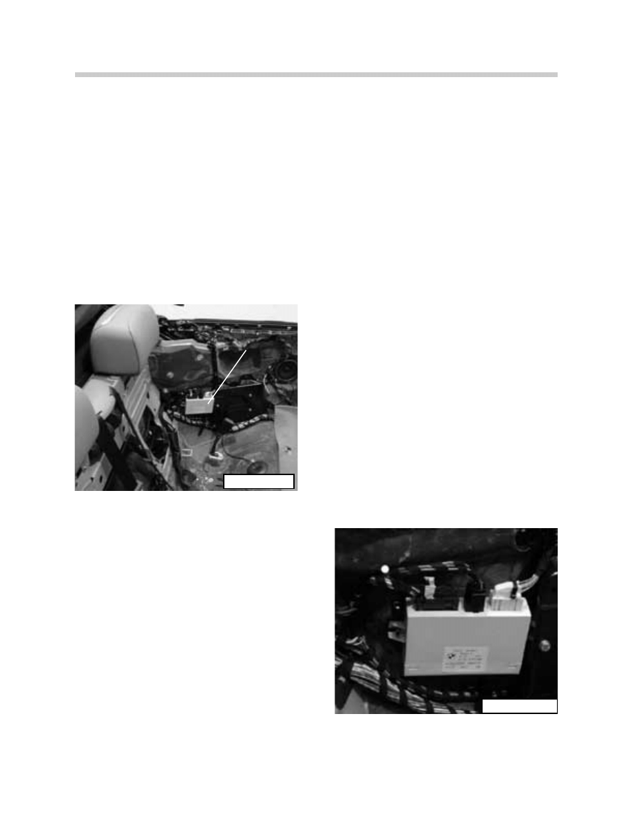
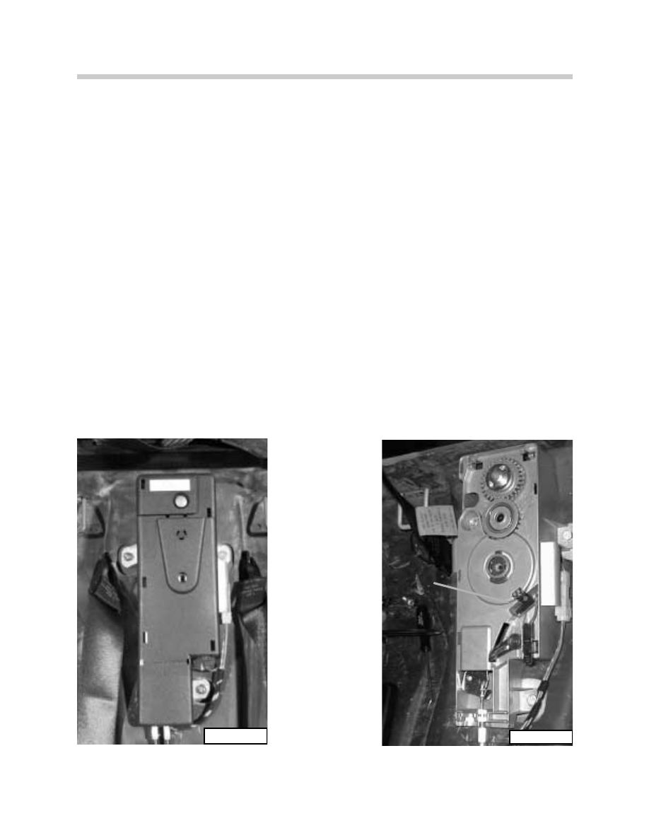
Convertible-Top Module (CVM II)
The convertible-top module (CVM II) is installed in the left rear quarter panel behind the inte-
rior trim panel. It contains the processing, controlling and monitoring electronics for the
complete top operation. The CVM II communicates with the GM over the K-Bus for opera-
tion of the top storage cover and windows.
Operation of the hydraulic cylinders is controlled via final stages and solenoids mounted on
the hydraulic unit and top frame.
The CVM is fully diagnoseable and contains a fault memory for storage of monitored faults.
Diagnosis is carried out over the K-Bus with the DIS or MoDiC.
CVM II
61E46CVM0300
61E46CVM0400
CVM II
6
CVM and Convertible Top
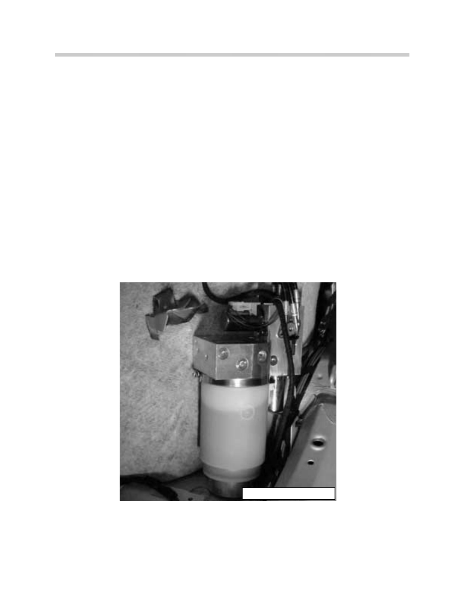
Hydraulic Unit
The hydraulic unit is mounted in the trunk on the left side behind the trim cover. It is mount-
ed on a rubber bushing and covered by sound insulation for noise reduction during pump
operation. The hydraulic unit consists of:
• Motor,
• Pump,
• Storage Cover Solenoid Valve/ Drain Solenoid Valve
• Reservoir.
• Temperature Sensor - hydraulic fluid
The hydraulic unit provides an operating pressure of up to 200 bar for the tops operation.
A temperature sensor on the hydraulic unit will signal the top module to cease operation if
the fluid temperature exceeds 95
0
C. Any function started will be completed before the sys-
tem is switched off. If the temperature exceeds 105
0
C, the system is immediately switched
off and the emergency closing procedure will be required for closing the top.
When the temperature drops below 95
0
, the operation of the top can be resumed.
Filling or checking the hydraulic fluid is only carried out when the top is lowered in the stor-
age compartment. The recommended fluid is “ARAL VITAMOL” PN 54 34 8 410 000 (Refer
to the repair manual for filling procedures)
54HYDRAULICPUMPE46050
7
CVM and Convertible Top
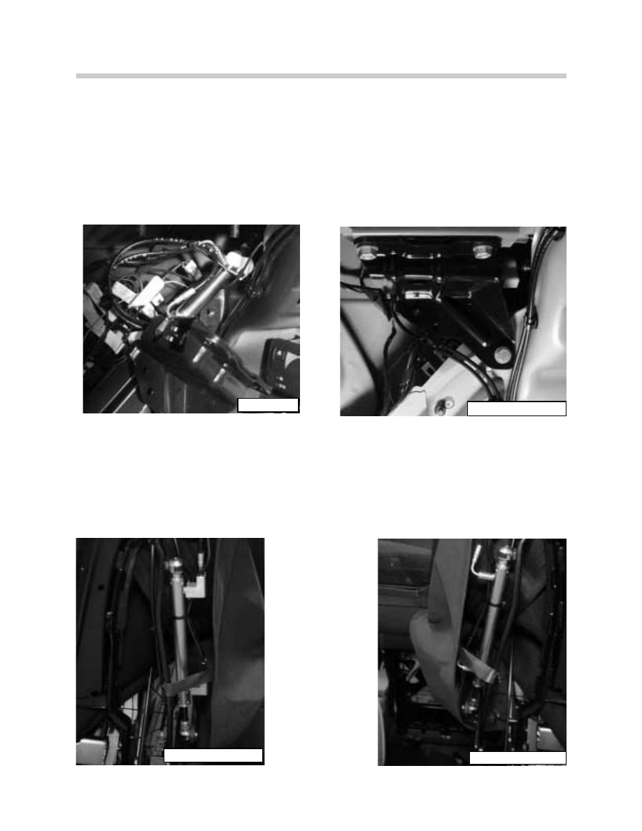
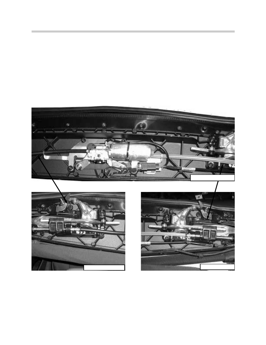
Hydraulic Cylinders
Top Storage Compartment Cover
Two hydraulic cylinders are positioned on the left and right sides in the trunk for opening
and closing the top storage compartment cover. A Hall sensor is positioned on the left
cylinder to detect the full opened position of the cover.
Cylinder Removed
Cylinder Installed
Tensioning Bow (Clamping Bracket)
Two hydraulic cylinders are positioned on the left and right sides of the tensioning bow, on
the top frame linkage for raising and lowering the bow. An angle hall sensor is installed on
the left tensioning bow linkage to detect the positioning of the bow. The hydraulic lines for
the right side tensioning bow cylinder are routed under the top fabric along the tensioning
bow.
Hall Sensor
54E46CYLINDER1200
54E46CYLINDER1300
54E46CYLINDER0900
ART-KT5355

8
CVM and Convertible Top
Main Pillar
Two hydraulic cylinders are positioned on the left and right sides of the top frame linkage
for raising and lowering the soft top frame. An angle hall sensor is used to detect the posi-
tioning of the main top linkage. The hydraulic lines for the right side main pillar cylinder are
routed under the top fabric along the tension bow.
A gas filled piston strut is mounted on the right side frame linkage, next to the hydraulic
cylinder, to dampen the raising and lowering of the top frame.
Gas Strut
54E46MAINPILLAR1000
54E46MAINPILLAR1100
54E46GASSTRUT0800
9
CVM and Convertible Top
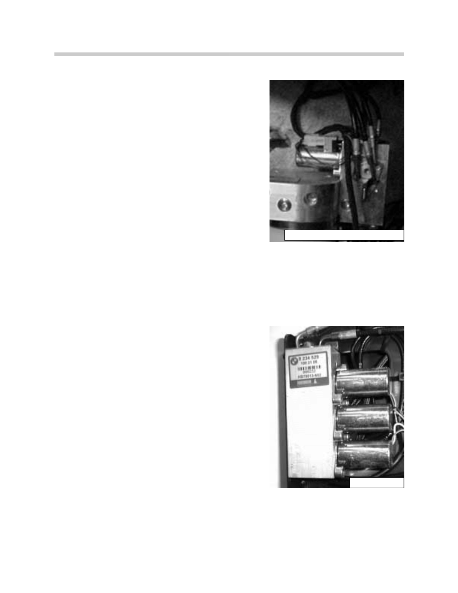
Hydraulic Solenoids
Two hydraulic solenoids are mounted on the hydraulic
unit:
• One solenoid valve (V1: I01043 convertible top
cover) controls the opening and closing of the
storage compartment cover
•
The second solenoid valve (V5: I01061, pressure
deactivation) is the drain solenoid for relieving
pressure in the hydraulic cylinders when the key is
switched off. The drain solenoid also holds system
pressure when the top switch is released during
operation.
Three hydraulic solenoids are mounted on the valve
block on the left side of the top frame.
•
Solenoid valve (V2: I01027, extend main pillar)
controls the operation of the main pillar hydraulic
cylinder.
•
Solenoid valve (V3: I01028, extend tensioning bow)
controls the tension bow hydraulic cylinders for
lowering.
•
Solenoid valve (V4: I01029, retract tensioning bow)
controls the tension bow hydraulic cylinders for
raising.
54E46HYDRAULICCONNECTOR0600
ARTSOLBLOCK
10
CVM and Convertible Top
Top Storage Compartment Cover Lock Motor
The top storage compartment cover lock motor is located on the drive shaft tunnel under
the rear seat. It consists of the motor with a hall sensor (S700), gear linkage assembly and
two bowden cables. Two locks are located on the right and left sides for locking the stor-
age compartment cover. The lock motor hall sensor (S700) detects the locked/unlocked
position of the storage cover.
During the soft top operation, when the tensioning bow is raised or when the top is in the
storage compartment, the CVM signals the GM over the K-Bus to unlock the storage com-
partment cover. The GM activates the lock motor and the motor turns 180 degrees to
unlock the cover latches. The motor always turns in the same direction to unlock/lock the
cover.
Once the motor has turned 180 degrees, the hall sensor (S700) input signal will cause the
GM to switch off the motor. At the same time, the GM will signal the CVM to continue top
operation.
C o n v e r t i b l e
Top Cover
Drive Switch:
S700
ART-KT-5380
ART-KT5382
11
CVM and Convertible Top
Windshield Frame Lock Assembly
The windshield frame lock assembly consists of the top lock motor positioned in the cen-
ter of the top frame and two lock drive mechanisms positioned on the left and right sides
of the top frame. The operation of the lock motor and drive mechanisms is similar to the
E36 fully automatic top system. The drive mechanisms have been redesigned for smoother
operation, however they still are responsible for unlocking the top from the windshield and
raising the front of the top past the tension point. Flexible drive shafts are used activate
the lock assemblies and drive the tension linkage rods to raise the top past the tension
position.
Two hall sensor switches located on the left lock drive assembly are used to detect the
position of the top against the windshield frame.
Right Lock Drive
Left Lock Drive
ART-TOPLOCKMOTOR
ART-TOPLOCKRIGHT
ARTOPLOCKLEFT

12
CVM and Convertible Top
Convertible Top Switch
The convertible-top switchs are located in the Center Console Switching Center (SZM).
There are two push button switches, one for each direction of travel, that provide a ground
input signal to the CVM for top operation.
Two LEDs are positioned in the center of the switch. The top LED will flash whenever the
top is in operation and not locked to the windshield frame or stored completely in the
compartment. The lower LED will illuminate, if the top switch is pressed and the storage
compartment floor is in the “UP” position.
OPEN ROOF
CLOSE ROOF
54E46covswitch0100
ART-E46ICCVMTOP
13
CVM and Convertible Top
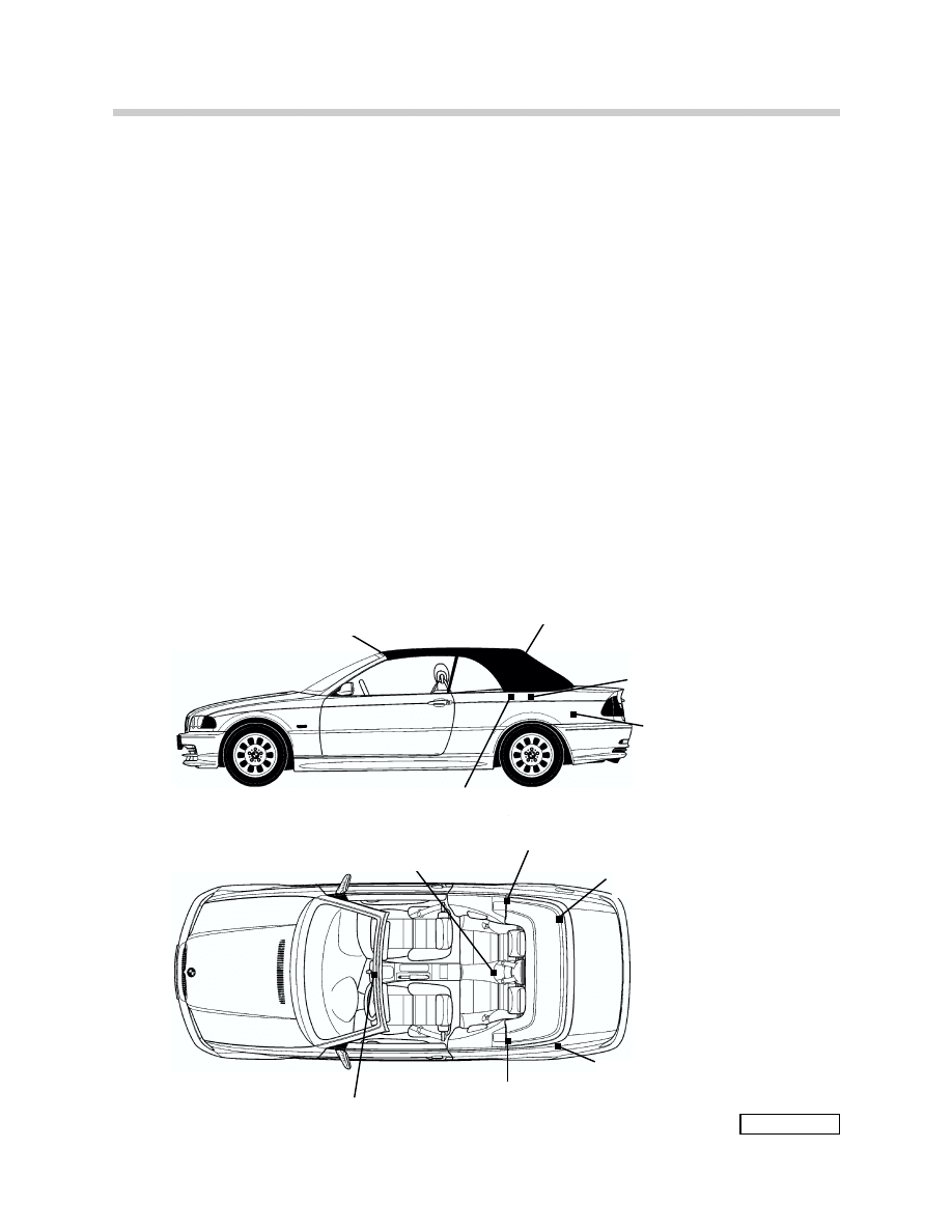
Sensors and Switches
The hall sensors, hall angle sensors and micro switches provide feedback status to the
CVM and GM for soft top positioning and top sequencing during operation.
Hall sensors:
•
Locking Hook Closed (cowl locked) hall sensor: S142
•
Locking Hook Open (cowl released) hall sensor: S145
•
Two Top Storage Compartment Cover Locks hall sensors: S161 and S158
•
Top Storage Compartment Cover hall sensor: S188
•
Top Storage Compartment Cover Motor hall sensor: S700
•
Hard Top Lock hall sensor: S164
Angle Hall sensors:
•
Tension Bow (clamping bracket) hall angle sensor: I01026
•
Main Pillar hall angle sensor: I01025
Micro Switch
• Top Storage Compartment Floor micro switch: S239
E46ICTOPUP.
Hall Sensors:
S142
S145
Hall Angle Sensor:
I01026
Hall Angle Sensor:
I01025
Hydraulic Unit
Hydraulic Solenoid
Valve Block
Hall Sensor:
S700
Component
Locations
Hall Sensor: S161
Micro-switch:
S239
Hall Sensor:
S188
Hall Sensors:
S158
S164
Top Switch

14
CVM and Convertible Top
Windshield Frame Lock Drive Hall Sensors
Two hall sensor switches are installed on the left side top lock drive assembly. Both sen-
sors receive power and ground from the CVM. One switch is the soft top locked to the
windshield frame (S142 cowl locked/locking hook closed). The second switch is the
locking hooks of the convertible top open (S145 cowl released/Locking hook open). As
the slide assembly on the worm gear moves, it covers and uncovers the hall sensors to
cause the high/low switching to take place.
The “Locking hook closed” (S142) input provides a high signal when the top frame is locked
and a low signal when it is unlocked from the windshield (LED in the soft top switch will start
to flash).
The “Locking hook open” (S145) input provides a high signal when the top frame is raised
past the tension point.
Note: The Diagnosis Requests list in Control Unit Functions refers to a “CONVERTIBLE TOP LOCKED” switch
input (S141). That display is a redundant signal from switch S142. Production E46 Convertibles are not fit-
ted with S141.
Locking Hook Closed Sensor
Locking Hook Open Sensor
ART-HALLSENSORSTOPLOCK
ART-E46ICCVMHALL2X
S142, Cowl Locked
(Locking Hook Closed)
S145, Cowl Released
(Locking Hook Released)
15
CVM and Convertible Top
Storage Compartment Cover Lock Hall Sensors
There are two storage compartment cover lock hall sensor switches (S161: right, S158:
left) one mounted on each storage cover lock. The sensors receive power and ground from
the CVM. Each sensor input provides a high signal when the cover is unlocked and the
cover is raised by the hydraulic cylinders far enough to clear the latches.
When the storage cover is completely lowered by the hydraulic cylinders, the hall sensors
send a signal to the CVM. The CVM then signals the GM to re-lock the storage cover.
54E46COVERLOCK0700
ART-TPCVRLCK.CVM
S158
Left Side lock
S161
Right Side lock
16
CVM and Convertible Top
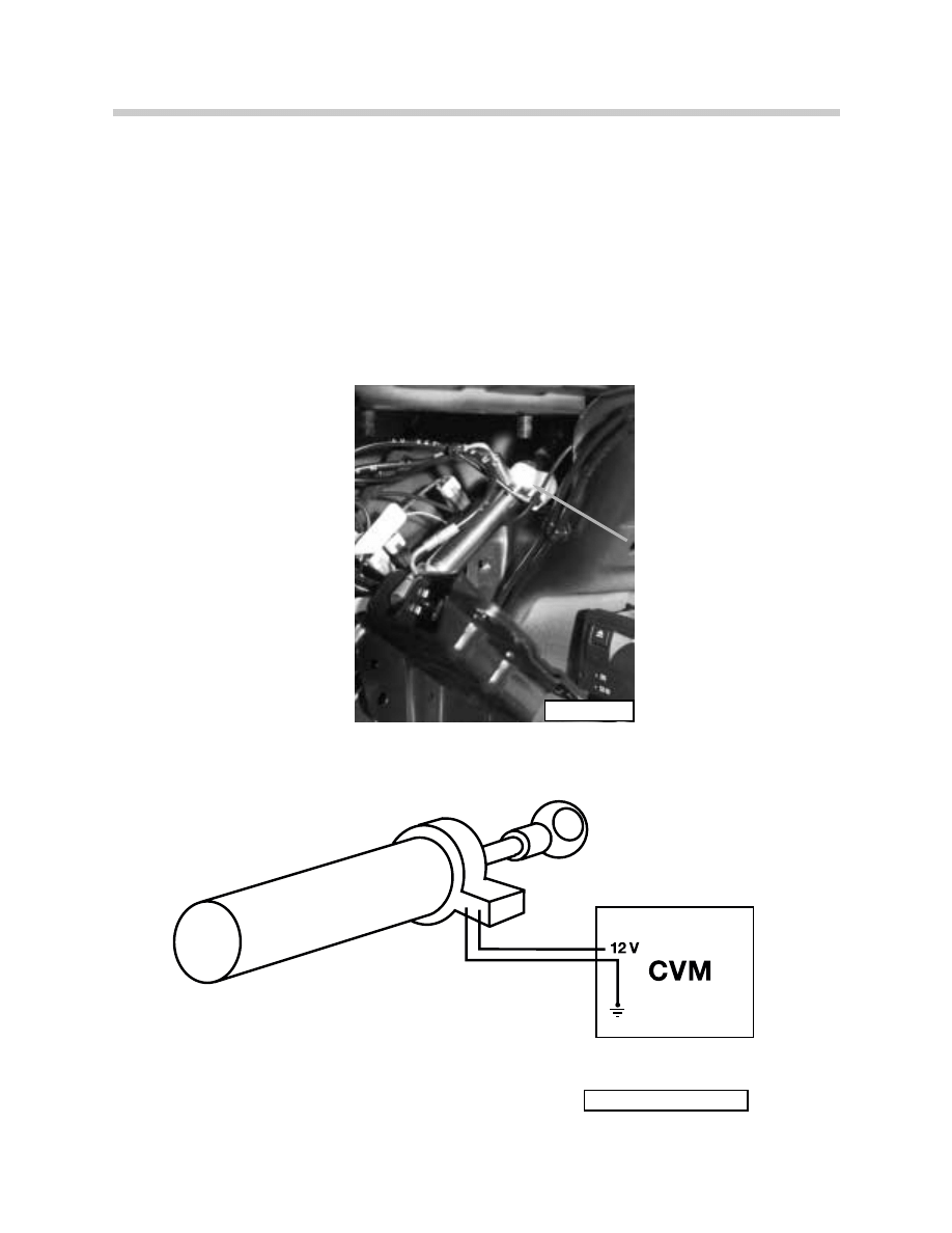
Storage Compartment Cover Hall Sensor (S188 Convertible Top Open)
The storage cover hall sensor switch (S188) is mounted on the left side storage cover
hydraulic cylinder in the trunk. It receives power and ground from the CVM. The switch
provides a high signal input when the top storage cover is fully open.
The CVM uses the signal from the switch for top storage cover positioning and switching
operation during soft top lowering and raising. The CVM uses this input signal as a switch-
ing point for activating the tensioning bow solenoid (V3) during top lowering or activation of
the main pillar solenoid during top raising.
S188: (Convertible Top
Open sensor)
ART-E46ICCVMRAMROD
ART-KT-5355
Trunk-Left Side
S188
Convertible
Top Open
17
CVM and Convertible Top
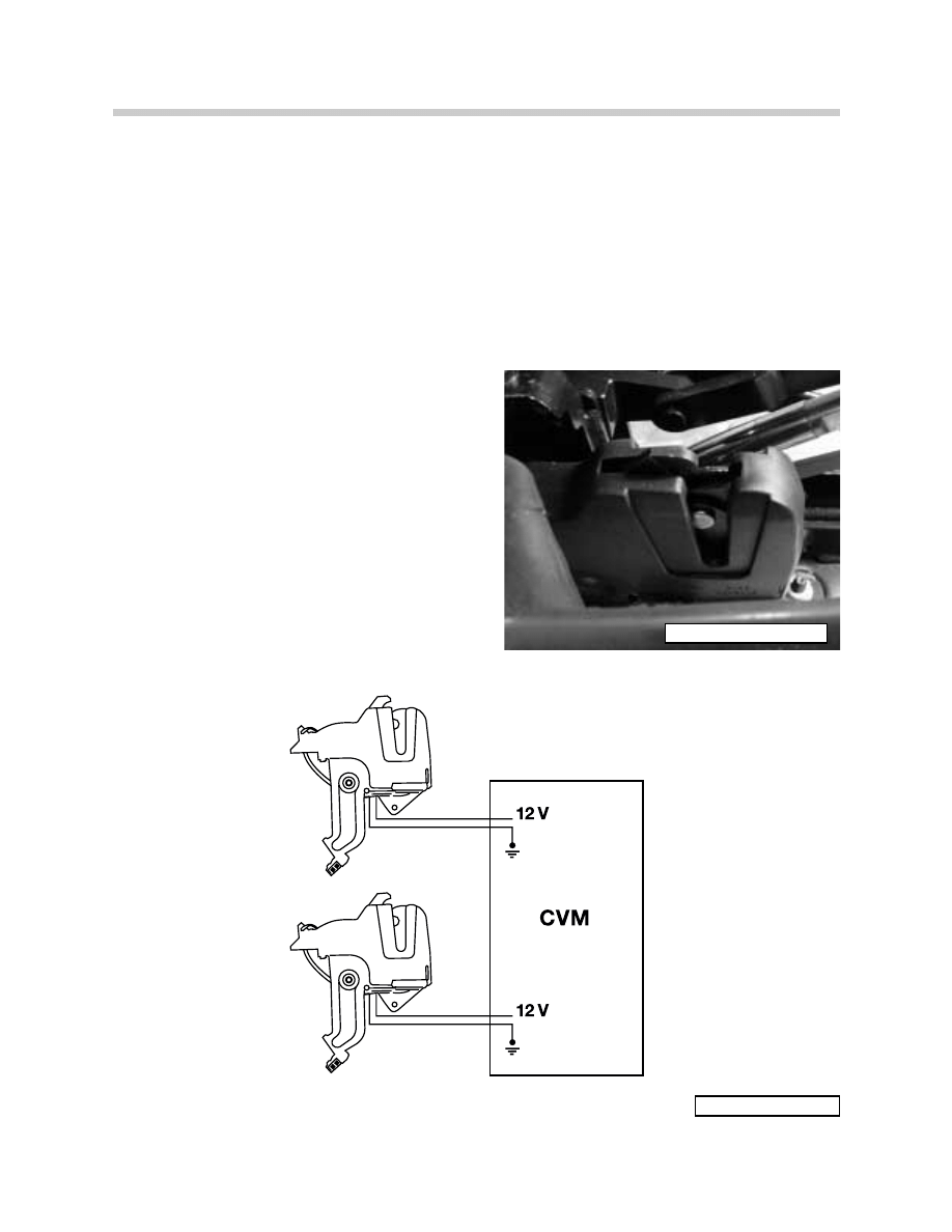
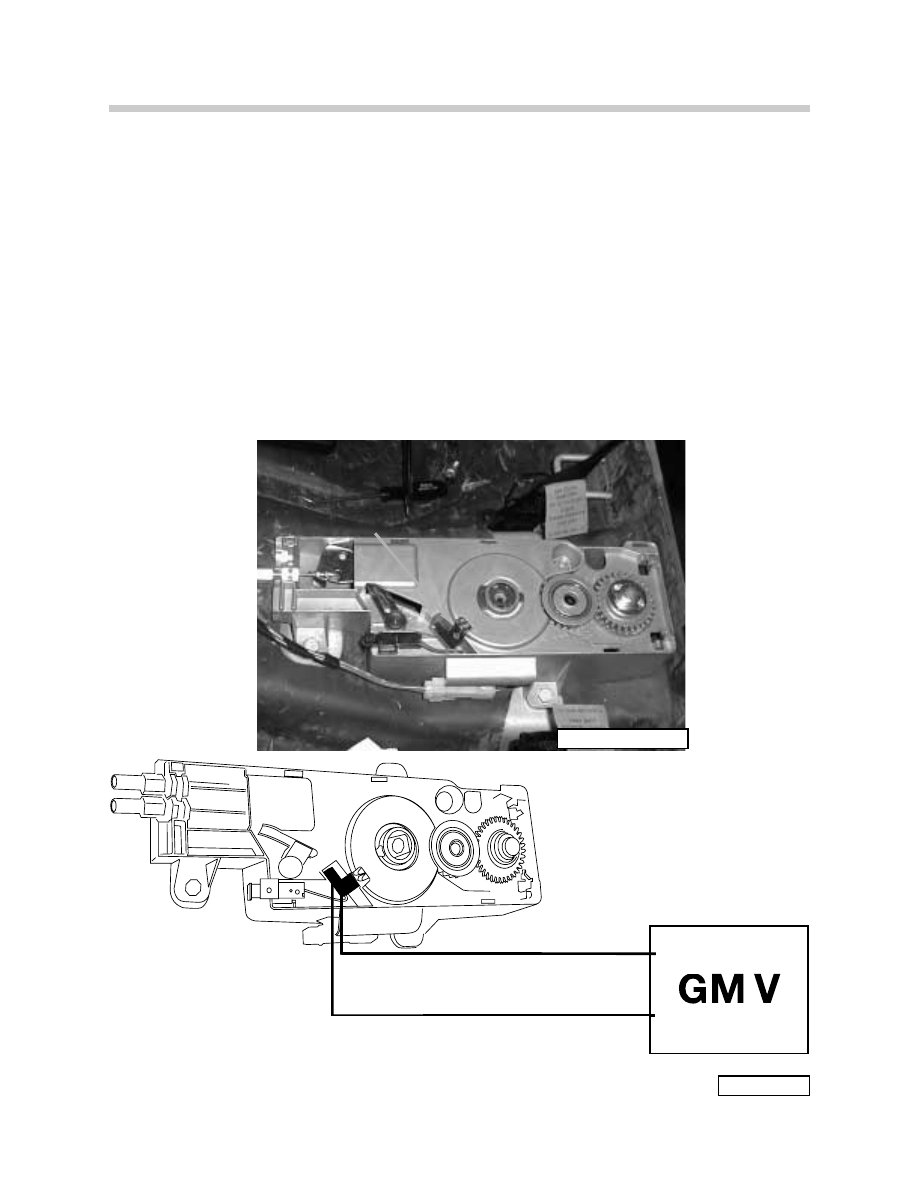
Storage Compartment Cover Motor Hall Sensor (S700 Switch, Convertible Top
Cover drive)
The storage cover motor hall sensor (S700) is mounted on the gear drive assembly of the
motor. It receives voltage from the General Module.
The GM uses this input to switch the unlock motor “OFF”. Additionally, the GM will electri-
cally lockout the trunk any time the storage cover is unlocked. The CVM receives a signal
over the K-bus of the unlock/lock status of the storage compartment cover.
S700
Convertible Top
Cover Drive Sensor
E46ICGM12V.
ART-COVERLOCK
S700 Convertible Top Cover
5V

18
CVM and Convertible Top
Hard Top Lock Hall Sensor (S164 Switch, Hard Top Recognition)
The hard top recognition hall sensor is positioned on the left hard top lock. It receives
power and ground from the CVM and provides a high signal input when the hard top is
installed on the vehicle. The connector on the top of the lock is used as the power and
ground supply for the rear window defroster of the hard top.
The CVM uses the input signal of the hall sensor to lock out soft top operation while the
hard top is installed.
54E46CVM1400
ART-MV563
HRDTPLCK.CVM
S164
Hard Top
Recognition

19
CVM and Convertible Top
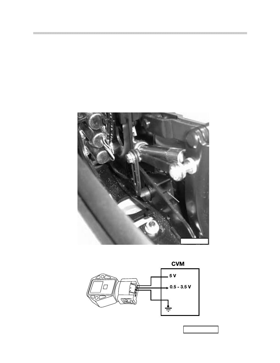
Tensioning Bow (Clamping Bracket) - Hall Angle Sensor
(I01026 Position Switch, Tensioning Bow)
The angle sensor for the Tensioning Bow is mounted on the left side of the top linkage by
the Tensioning Bow hydraulic cylinder. The angle sensor receives power (5 volts) and
ground from the CVM. It provides a linear voltage signal input from approximately 0.5 to
3.5 volts as the Tensioning Bow moves from a vertical to horizontal position.
The CVM uses the signal from the Tensioning Bow angle sensor to determine positioning
of the tensioning bow and switching operation during soft top lowering and raising.
61E46ANGLEHALLSENSOR0500
ART-E46ICTENBOW.
I01026 Position Switch
Tensioning Bow
20
CVM and Convertible Top
Hall Angle Sensor - Main Pillar
(I01025 Position Switch, Main Pillar)
The angle sensor for the Main Pillar is mounted on the left side top linkage by the left main
pillar hydraulic cylinder. The angle sensor receives power (5 volts) and ground from the
CVM. It provides a linear voltage signal input from approximately 0.5 to 3.5 volts as the top
frame is lowered into and raised out of the storage compartment.
The CVM uses the input signal from the Main Pillar angle sensor for top frame positioning
I01025
Position
Switch, Main Pillar
ART-MNPIHS
E46ICMAINPILL
I01025 Position Switch
Main Pillar
21
CVM and Convertible Top
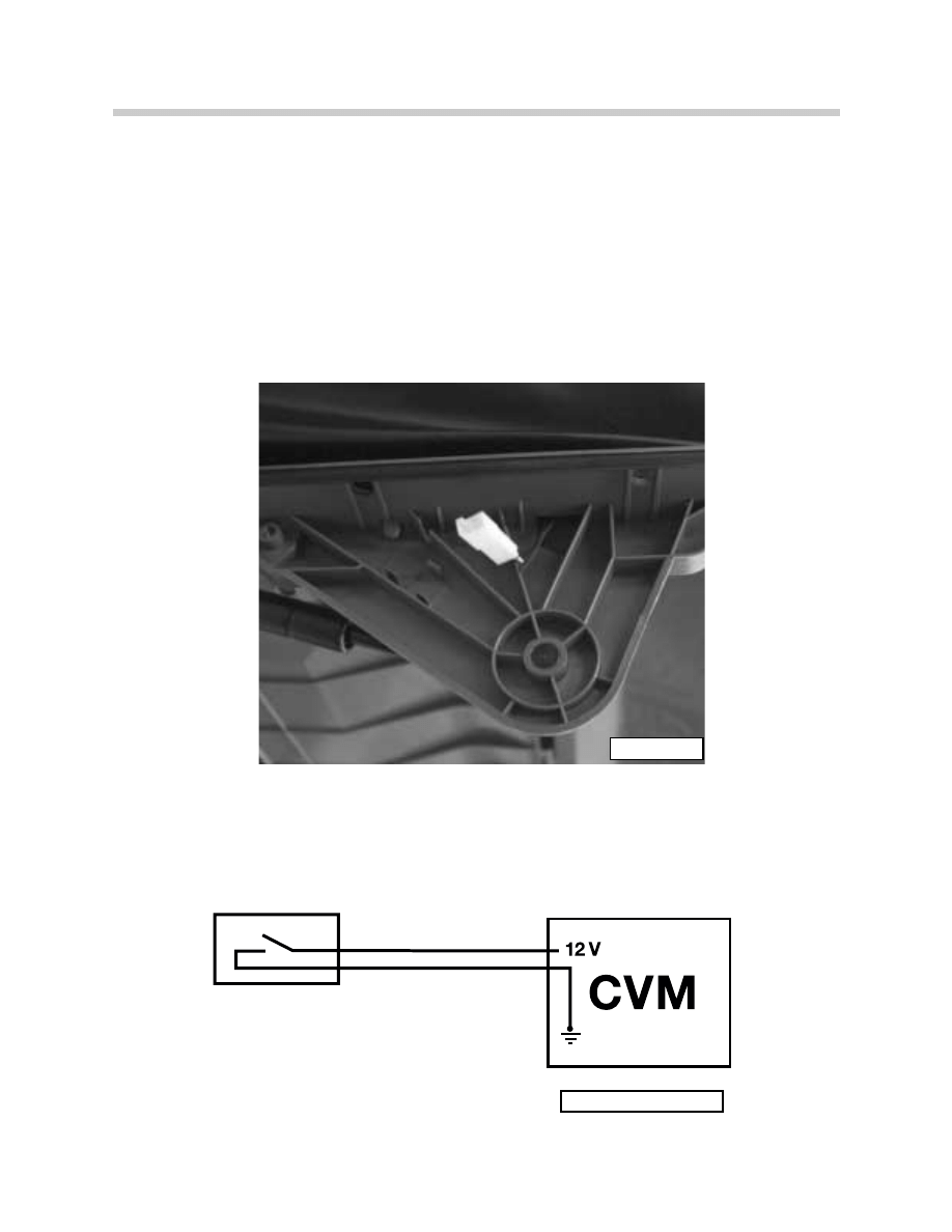
Storage Compartment Floor Micro-Switch
(S239 Switch, Convertible Top Compartment Floor)
The Storage Compartment Floor micro-switch is installed on the hinge of the compartment
floor on the right side. It provides a high/low input signal to the CVM based on the posi-
tion of the compartment floor.
When the floor is in the raised position, the soft top operation is locked out.
S239 Convertible Top Compartment
floor Switch
ART-KT5433
ART-E46ICCVM12V.EPS
22
CVM and Convertible Top
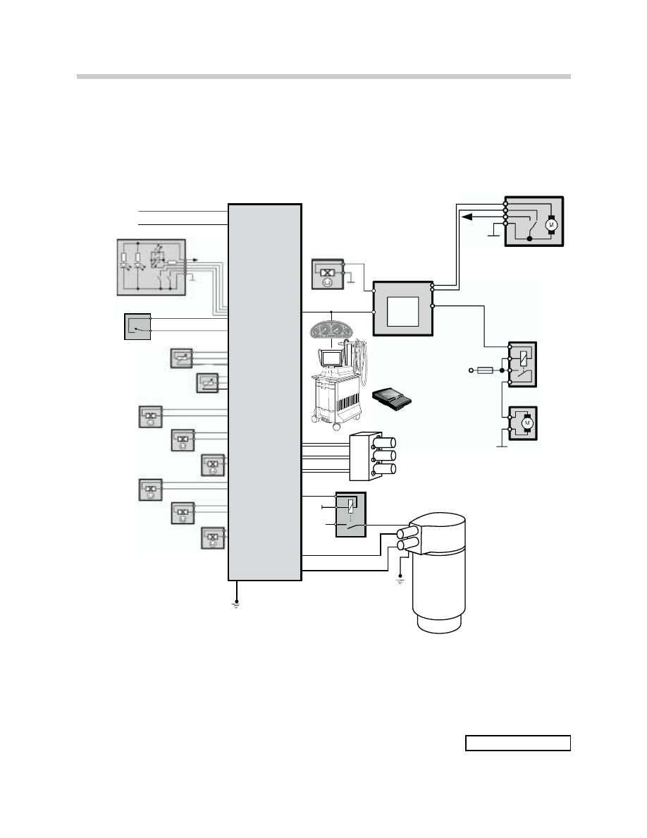
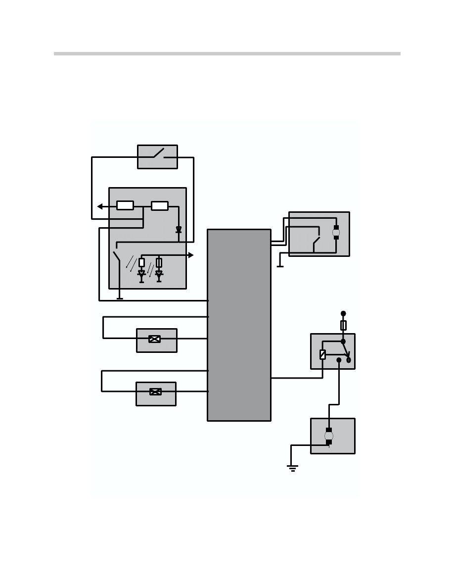
CVM IPO
KL 30
KL R
TOP SWITCH
COMPARTMENT FLOOR
MICRO-SWITCH: S239
GM V
KL 30
STORAGE COVER
MOTOR
TRUNK LOCK ACTUATOR
MAIN PILLAR SOLENOID: V2
TENSIONING BOW SOLENOID
EXTEND: V3
TENSIONING BOW SOLENOID
RETRACT: V4
HYDRAULIC
UNIT
ANGLE SENSOR
TENSIONING BOW: I01026
ANGLE SENSOR
MAIN PILLAR: I01025
STORAGE COVER
LOCKED LEFT: S158
CVM
CONVERTIBLE TOP
COVER DRIVE HALL SENSOR:
S700
K-BUS
KL 31
KL 30
MoDiC
Mo
DiC
58 g
TRUNK
LIGHT
HALL SENSORS
STORAGE COVER
LOCKED RIGHT: S161
STORAGE COVER OPEN: S188
LOCKING HOOK ,
CLOSED: S142
LOCKING HOOK,
OPEN: S145
HARD TOP
LOCK: S164
STORAGE
COVER SOLENOID: V1
DRAIN SOLENOID: V5
BMW
DIS
BMW D
IS
BMW
DIS
BM
W
DI
S
DISplus
K18363
CONVERTIBLE TOP
RELAY 1
I01042
CONVERTIBLE TOP
DRIVE RELAY
ART-E46ICEHYDD.EPS
23
CVM and Convertible Top
System Operation
Pre-Conditions for Soft Top Operation
•
Ignition key in position “R” - (Except for comfort operation)
•
Road speed < 2.5 MPH
•
Hydraulic unit temperature < 95 degrees
•
Trunk lid closed
•
Top storage compartment floor in lower position with top raised
•
No hard top installed with top lowered
In addition, there must be no faults present at
any of the switch inputs or outputs.
Top Lowering Sequence
Top Switch Pressed “Open”
•
CVM activates the top lock motor and the
top is unlocked and raised past the tension
point (LED switch flashing).
•
At the same time, the CVM signals the GM
to lower the windows (if closed) for
approximately 1.5 seconds.
•
Top lock motor is switched OFF - signal from cowl released hall sensor (S145).
ART-TOPDOWN1

24
CVM and Convertible Top
•
CVM activates hydraulic pump and switches the tension bow solenoid (V4) to raise the
tension bow.
•
Tension bow is raised to its vertical position - signal from tensioning bow angle hall
sensor.
•
CVM signals GM to unlock storage compartment cover.
•
Storage compartment cover unlocked - signal from motor hall sensor (S700) - storage
cover lock motor is switched off.
•
CVM receives status of cover lock from GM over K-bus - switches storage cover
solenoid (V1).
•
Storage cover raised to its open position -
signal from cover hall sensor (S188).
•
CVM switches to the lowering solenoid for the
tension bow (V3) - top starts lowering into
storage compartment.
•
CVM switches the main pillar solenoid (v2) -
top is fully lowered into storage
compartment.
54E46TOPLOWERING0000
ART-TOPDOWN3
25
CVM and Convertible Top
•
CVM switches solenoid for top cover (V1) - cover is lowered - signal from storage cover
lock hall sensors (S161 and S158).
•
CVM signals GM to lock storage compartment cover.
•
GM activates cover lock motor - cover is pulled closed by lock assemblies.
•
GM switches off lock motor - signal from motor hall sensor (S700).
•
CVM switches off hydraulics and LED.
Top Raising Sequence
Top Switch Pressed - “Closed”
•
Windows are lowered (if closed) - CVM to GM
•
Storage compartment cover is unlocked - CVM to GM
•
Storage cover is opened
•
Top is raised out of storage compartment
•
Tension bow is raised
•
Storage cover is closed
•
Storage cover is locked - CVM to GM
•
Tension bow is lowered
•
Top is lowered and locked to cowl - Top locked, is confirmed by S142 and Tensioning
bow angle sensor (Tensioning bow horizontal)
•
Windows are closed - if switch is held
ART-TOPDOWN4

26
CVM and Convertible Top
Hydraulic System Operation
The pump in the hydraulic unit is energized by the CVM and supplies hydraulic fluid under
pressure to the solenoids mounted on the pump and solenoid valve block. The solenoids
are energized by the CVM and the pressure is supplied to the hydraulic cylinders, based on
the input signals from the angle hall sensors and hall switches. The hydraulic operation of
the solenoids and cylinders is as follows:
• The storage cover cylinders receive hydraulic pressure on the lowering side of the piston
ram when the hydraulic pump is energized. When the solenoid is energized, hydraulic pres-
sure is applied to the raising side of the ram. The cover is opened because the greater rais-
ing pressure overcomes the pressure on the small side of the ram. When the cover is low-
ered, the solenoid switches to drain and the lowering pressure closes the cover.
• The main pillar cylinders receive hydraulic pressure on both sides of the ram when the
pump is switched on. The main pillar solenoid is switched to drain to lower the top frame
into the storage compartment. The solenoid is switched to pressure to raise the top frame
out of the storage compartment. The greater pressure on the raise side of the piston will
overcome the lowering pressure to raise the frame.
• The raise tension bow solenoid is energized to apply pressure to the tension bow cylin-
ders and raise the tension bow. The tension bow lower solenoid is switched to drain.
• The lower tension bow solenoid is energized to supply pressure to the tension bow cylin-
ders to lower the tension bow. The tension bow raise solenoid is switched to drain.
• The drain solenoid is energized whenever the pump is switched on. It holds pressure in
the system when any of the cylinder solenoids are not energized. It also holds pressure in
the system if the top switch is released during operation.
The drain solenoid is switched when the hydraulic pump is switched off as the top reach-
es one of its end positions. This allows the pressure in the cylinders to be relieved and
drained back to the reservoir.
The drain solenoid switches off as the key is switched off. This will cause the pressure to
drain slowly in steps.

27
CVM and Convertible Top
Hydraulic System Operation
ART-E46ICCVM.EPS
ART-E46IC E HYD.EPS
28
CVM and Convertible Top
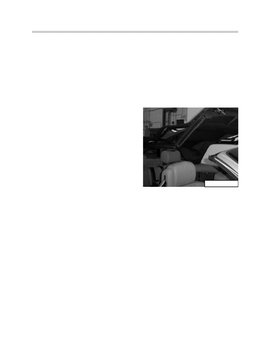
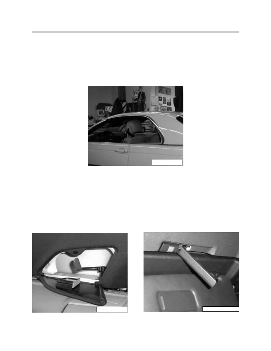
Emergency Operation
Emergency locking/unlocking of the top stor-
age cover is carried out at the motor assembly.
The motor assembly is accessed by removing
the center arm rest and lifting the seat uphol-
stery below the ski bag.
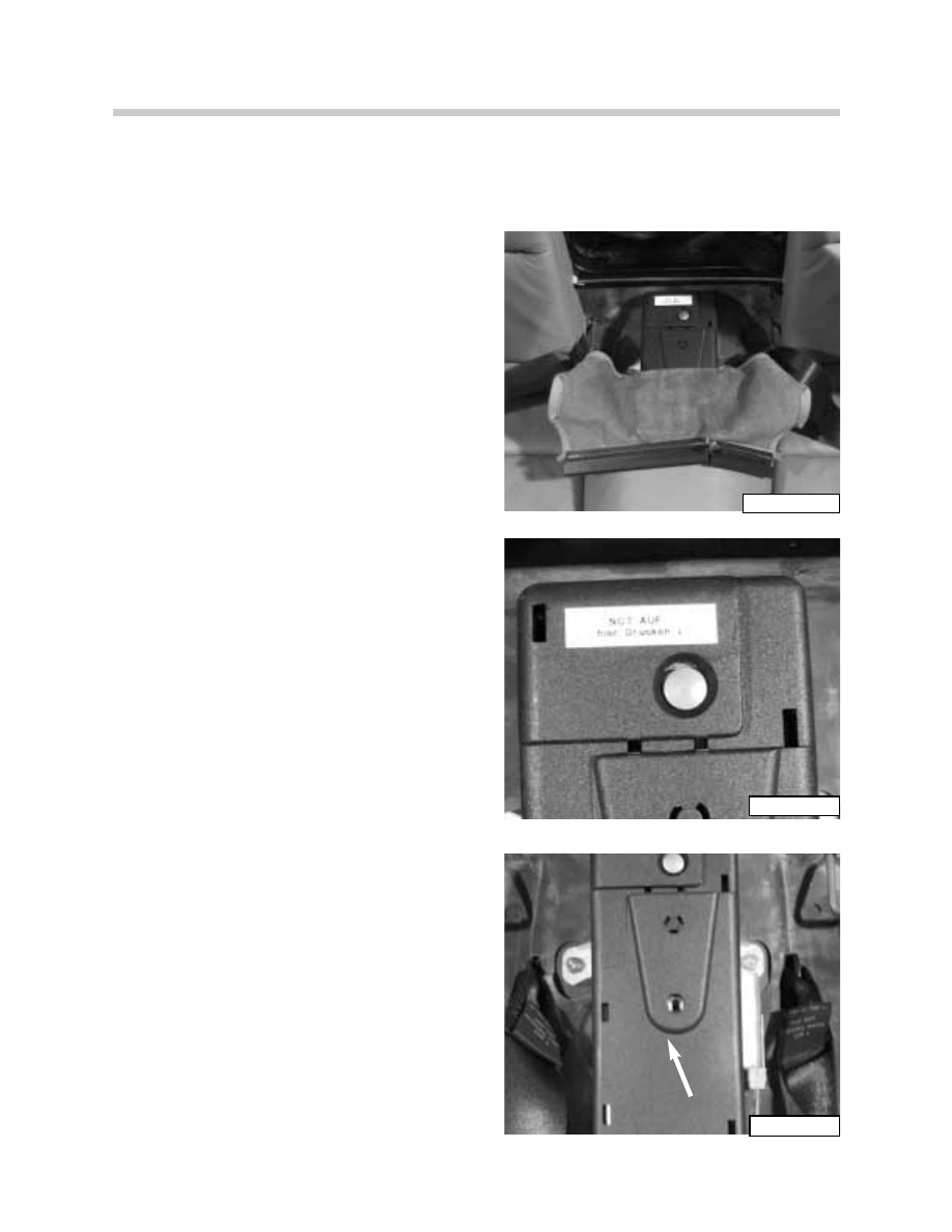
Pressing the button on the motor assembly will
release the motor from the gear linkage.
The linkage assembly can then be turned,
through the access hole in the motor assembly
cover, using the hand crank stored on the
assembly cover. This will unlock/lock the stor-
age cover locks for manually raising the top.
Release Button
Manual
Crank
ART-KT-5384
ART-KT5379
ART-KT-5380

29
CVM and Convertible Top
Comfort Closing/Opening
Comfort closing/opening of the top is possible at the driver’s door lock cylinder. If the key
is held in the locking position the top will be raised and the windows closed in the raising
sequence.
If the Variable Storage Compartment floor is in the raised position only the windows will be
lowered during the convenience opening sequence.
Residual Closing/Opening
It is possible to finish raising or lowering the top at speeds > 2 MPH if:
•
The signal from the main pillar angle sensor indicates that the top is fully extended out
of the storage compartment.
•
The signal from the main pillar angle sensor indicates that the top is fully lowered in the
storage compartment.
Safety in the Intermediate Positions
All movements of the top stop once the switch is released. The hydraulics hold the position
of the top and remain under pressure for approximately 20 minutes if the ignition key is left
in the ON position.
If the ignition is switched OFF, in the intermediate position, the pressure will be released in
steps after approximately 10 seconds until all pressure is drained from the cylinders. This
allows the top to be manually moved for servicing procedures.
NOTE: Depending on the position, the top may collapse into the storage compartment if
the ignition is switched off with the top in the partially raised position.

30
CVM and Convertible Top
Fault Memory
The fault memory of the CVM is stored in an NVRAM which can store up to a maximum of
16 faults. The fault are stored in the order of occurrence and a distinction is made between
permanent and sporadic faults.
Operation in the Event of Faults
If a fault occurs during raising or lowering the top, all movement will cease and the fault will
be stored in the fault memory. The emergency closing procedure must be used to close the
top and the vehicle taken to the dealership for repair.
Depending on the location and type of fault, it may be possible to raise or lower the top fully
by pressing the switch in the opposite direction from which the fault occurred.
If the top switch is held > 20 seconds after completing a raising/lowering procedure, a fault
will set in the CVM. The control module assumes a fault to ground in the switch or lead. The
ignition switch must be cycled to clear the fault before the top will again function. The fault
will remain in the module until cleared with the Tester or MoDiC.
All sequenced movements of the top have time out limits set in the control module. If a time
out occurs before the end position is reached, the specific movement will be switched off
to prevent damage to any of the top components.

31
CVM and Convertible Top
E46iC MANUAL TOP
The E46iC - 323/325 models are equipped with a manual top as standard equipment.
Raising or lowering the top frame assembly is carried out by hand. However, the manual
top features an electrically operated storage cover lock system. The unlocking/locking of
the storage cover is a function of the general module.
The frame of the manual top is similar to the fully automatic system, with two piston
dampers mounted on the assembly to aid in its operation. The front of the top frame fea-
tures a manual handle that is used to operate the cowl locks on the left and right sides.
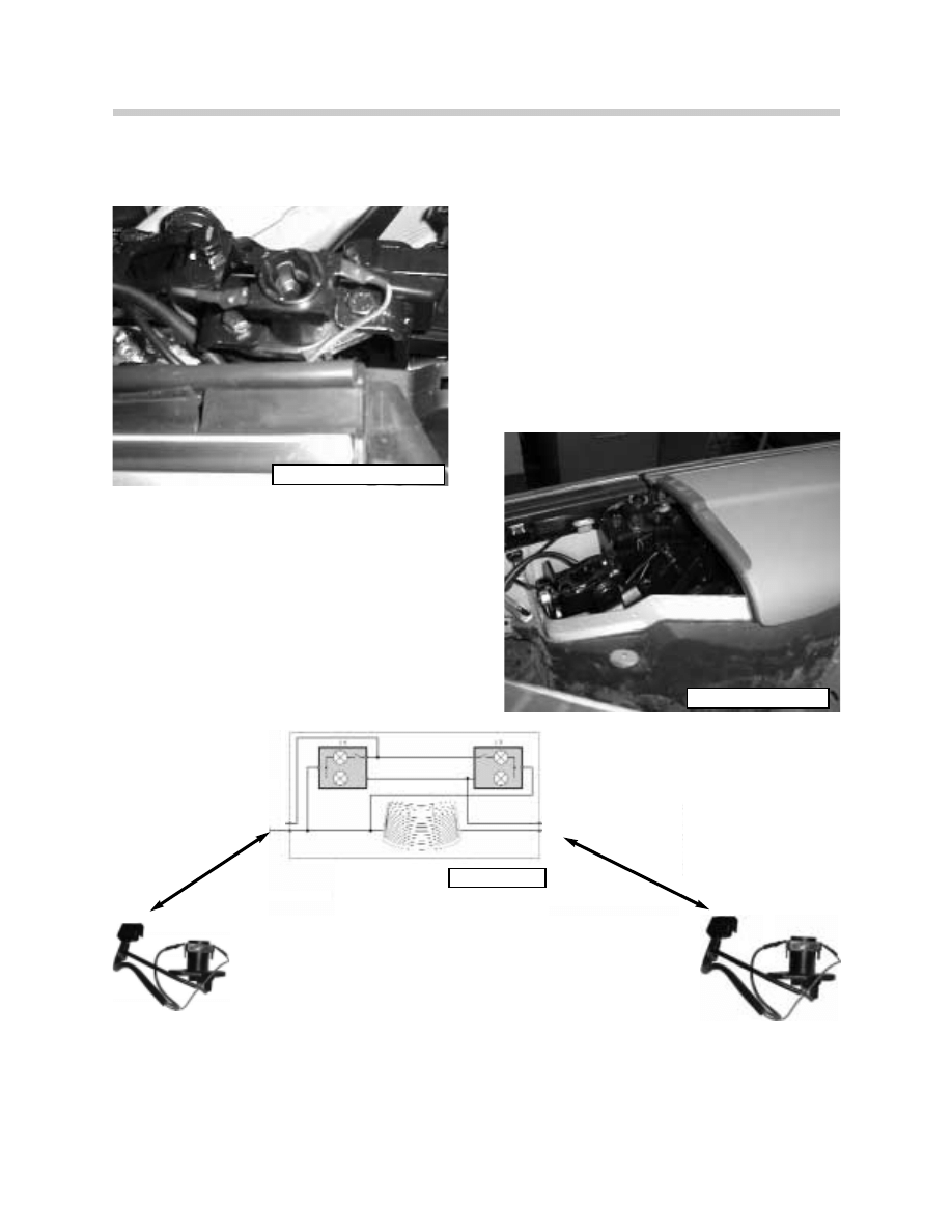
MANUAL TOP STORAGE COVER OPERATION
The storage cover locking assembly consists of the following components:
• General Module
• Switch assembly
• Storage Cover Motor assembly - with hall sensor and bowden cables
• Two Storage Cover Locks - with a hall sensor
• Variable Top Storage Compartment Floor - micro switch
When the button is pressed to unlock the storage cover, the GM will lower the windows and
activate the relay to unlock the storage cover. After raising the tension bow, the storage
cover is raised manually and the top is lowered into the storage compartment. The storage
cover is then lowered onto the locks and the signals from the storage cover hall sensors
will signal the GM to relock the cover.
The signal from the variable storage compartment floor micro switch will prevent the stor-
age cover from opening when the floor is in the open position.
The GM will lock out the operation of the storage cover lock motor whenever the trunk is
opened.
32
CVM and Convertible Top
M
M
Compartment Floor Micro Switch
KL30
Trunk Lock
Hall Sensor Storage Cover
Hall Sensor Cover MTR.
Storage Lock Motor
KL 5 8 G
Top Switch
KL30
GM V
Manual Top Storage Cover Operation Diagram
61460014
33
CVM and Convertible Top
Hard Top
An accessory hard top is available for the E46iC. It is constructed from aluminum with a
finished fabric upholstery on the inside. Roof rack mounting points are integrated into the
top on the left and right sides.
The hard top attaches to the vehicle at four places:
• Two hard top locks on the left and right sides in the rear.
• Two cowl locks at the front.
ART-HARDTOP
ART-HLOCK1
ART-HRT-HLOCK2
34
CVM and Convertible Top
The hard top locks on the left and right, in the rear, have integrated wiring connectors for
power and ground supplies to the rear window defogger and interior lights.
The connector on the left side contains two
separate strips, one for power supply to the rear
defogger and the other for power supply to the
interior lights
The connector on the right side contains two
separate strips, one for the ground connection
for the rear defogger and the other for
Ground &
GM V control
Power &
GM V control
ART-HARDTOPLOCKLEFT
ART-HARDTOPCONN
ART-KT5260
ART-HARDTOP2
ART-HARDTOP2

35
CVM and Convertible Top
Workshop Hints:
Convertible Removal/Installation Top
This section of the handout will cover highlights of soft top removal and installation. The
“REPAIR MANUAL” should always be referenced for the complete procedure on top
removal/installation and adjustments. Removal of the soft top assembly requires removing
the rear seat and interior trim panels to gain access to the fastening points and wiring con-
nections.
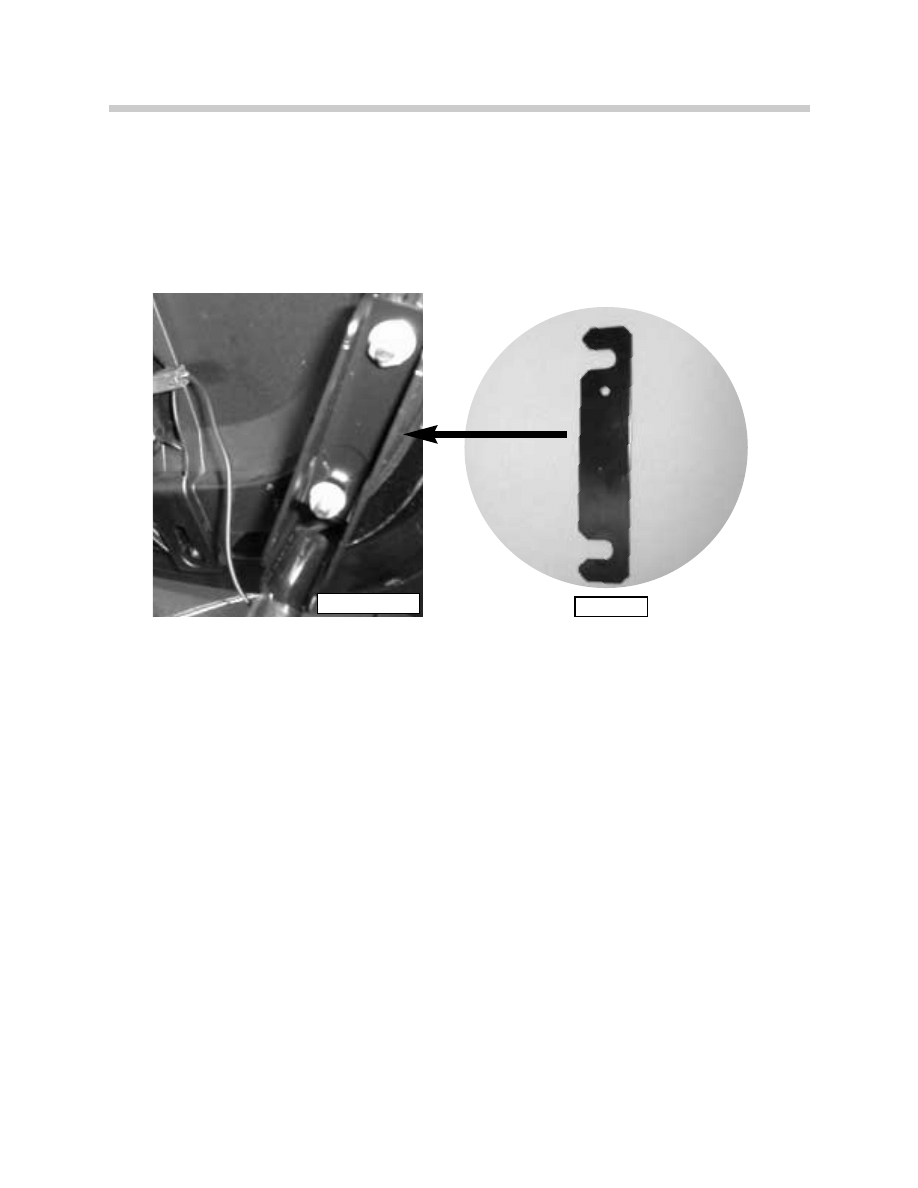
The top storage cover should be removed prior
to removing the top assembly. The hard top
lock post and storage cover locks must be
removed from the top frame assembly. The
cover locks are connected to the unlock motor
through a bowden cable that must be discon-
nected when removing the lock assemblies.
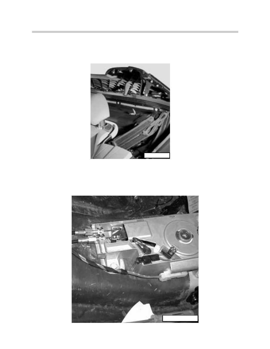
The top and frame assembly is bolted to the
main top bracket at four points. The top must
be raised with the tension bow in the vertical
position to access three of the nuts.
The fourth mounting point for the top frame
assembly is on the front of the top mounting
bracket. This should be loosened after the top
is lowered into the storage compartment.
Bowden Cable
Fastening Points
ART-FRBOLLOC
ART-FRBOLLOC1
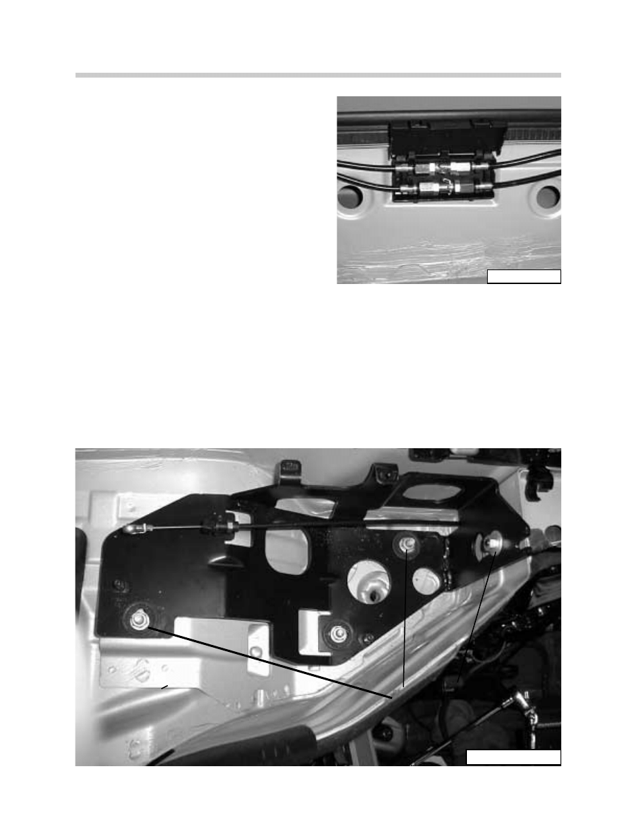
The supply and drain lines from the hydraulic
unit to the solenoid block on the top frame are
connected through quick disconnect couplings
located on the left side of the top storage com-
partment. Care should be taken when discon-
necting the lines not to drip the hydraulic fluid
onto the top fabric.
Ensure that all wiring is disconnected from the top frame before removing the top assem-
bly. There are three connectors on each side of the top assembly in front of the top stor-
age compartment. The main wiring harness (18 Pin ELO) from the CVM to the top frame
must also be disconnected.
THE TOP FRAME IS UNBOLTED FROM THE FRAME MOUNTING BRACKETS, MOUNT-
ED IN THE STORAGE COMPARTMENT. THESE BRACKETS ARE PRE-SET AND
ADJUSTED FOR TOP ALIGNMENT AT THE FACTORY AND MUST NOT BE REMOVED OR
ADJUSTED WHEN CARRYING OUT SERVICE WORK ON THE TOP.
Frame Bracket
Set at Factory
ART-HYDLINES
ART-TOPFRAMECON
37
CVM and Convertible Top
Service Adjustments
The convertible top storage compartment cover is made of magnesium, a spacer plate
must be used when installing the cover to the mounting brackets. the brackets have elon-
gated holes for adjustment of the cover to the body.
The height of the rear of the storage compartment cover is adjusted at the mounting brack-
ets for the hydraulic cylinders located in the trunk. This adjustment must be carried out by
removing the rear tail light assemblies due to the lock out of the trunk lid and storage cover.
ART-SHIM.
ART-ANTEMP
38
CVM and Convertible Top
The front of the storage compartment cover is adjusted at two places. The latch brackets
are mounted through elongated holes for alignment of the brackets to the cover latches.
The front of the storage compartment cover’s height is adjusted by adjusting the bowden
cable length at the storage cover lock motor. The cover should close flush with the body.
Bowden Cable
Adjustment
Latch Bracket
ART-KT4956
ART-COVERLOCK

NAME OF SIGNAL OR FUNCTION: Hall sensor inputs to the CVM
Vehicle: E46iC
M Y:
2000
System: Convertible Top - CVM
#1. Cowl Lock/Tension Point Hall Sensors:
The Cowl Lock input to the CVM is at pin# ____________ and pin# _____________.
The signal from the cowl lock sensor is _____________ volts with the top locked to the
cowl.
The signal from the cowl lock sensor is _____________ volts when the top is unlocked from
the cowl.
The status display on the DIS shows __________________ when the top is locked to the
cowl and ________________________ when the top is unlocked.
The Tension Point input to the CVM is at pin# _________ and pin# ____________.
The signal from the tension point sensor is ___________volts with the top locked to the
cowl.
The signal from the tension point sensor is ___________ volts when the top lock motor
switches off.
The status display on the DIS shows __________________ when the top is locked to the
cowl and ________________________ when the top lock motor switches off.
#2. Storage Cover Lock Hall Sensors:
The storage cover lock inputs to the CVM are at: pin# _______ and pin# ________ LEFT
pin# ______ and pin# ________ RIGHT
The signal from the storage cover lock sensor is _________ volts when the cover is closed
and locked.
The signal from the storage cover sensor lock is _________ volts when the cover is
unlocked.
The status display on the DIS shows ____________________ when the cover is closed and
locked and _______________________________ when the cover is unlocked.
#3. Storage Cover Hall Sensor:
The storage cover input to the CVM is at pin#____________ and pin # ___________.
The signal from the storage cover sensor is _________ volts when the cover is closed.
The signal from the storage cover sensor is _________ volts when the cover is open.
The status display on the DIS shows ________________________ when the cover is closed
and ________________________________ when the cover is open.
39
CVM and Convertible Top

NAME OF SIGNAL OR FUNCTION: Angle Hall Sensor inputs to CVM
Vehicle:
E46iC
M Y:
2000
System: Convertible Top - CVM
#1. Main Pillar Angle Hall Sensor:
The power supply for the main pillar angle hall sensor is ________ volts at pin # ________ of
the CVM and ground at pin # ______ of the CVM.
The input signal to the CVM from the main pillar sensor is _________ volts with the top fully
raised and _________ volts with the top lowered into the storage compartment.
The status display on the DIS of the main pillar sensor input is ______________________
with the top fully raised and _____________________________ with the top lowered into the
storage compartment.
#2. Tension Bow Angle Hall Sensor (Clamping Bracket):
The power supply for the tension bow angle hall sensor is _________ volts at pin # ______
of the CVM and ground at pin # ______ of the CVM.
The input signal to the CVM from the tension bow sensor is:
___________ volts with the top locked to the cowl.
___________ volts with the tension bow in the vertical position.
___________ volts with the tension bow lowered into the storage compartment.
The status display on the DIS of the tension bow input is:
__________________________ with the top locked to the cowl.
__________________________ with the tension bow in the vertical position.
__________________________ with the tension bow lowered into the storage compartment.
40
CVM and Convertible Top

41
CVM and Convertible Top
Review Questions
1. What are the major changes to the E46iC fully automatic top operation compared to the
E36iC?
2. How many hydraulic solenoids are used in the operation of the E46iC top?
3. The locking/unlocking function of the storage compartment cover is controlled by which
module?
4. Which hall sensors control the flashing of the LED in the top switch?
5. What happens to the soft top/frame if the ignition is switched off during its operation?
6. Describe the emergency closing procedure for the soft top:
7. What type of input is provided by the angle hall sensors for top operation?
8. The only micro switch used in the operation of the soft top is?
9. What indication is shown if the variable compartment floor is open when the top switch
is pressed?
Document Outline
- Return to Main Menu
- Models
- Part 1 Driver Information
- Part 2 Driver Information
- Central Body Electronics
- CVM
- Passive Safety System
- Climate Control
- Engines
- Part 1 Engine Management Sys.
- Part 2 Engine Management Sys.
- Automatic Transmission
- Part 1 Traction and Stability
- Part 2 Tracton and Stability
Wyszukiwarka
Podobne podstrony:
Grice Logic and Conversation OPRACOWANIE(1) id 195809
Dungeons and Dragons suplement New and Converted Races for D&D 3 5 Accessory
Telling rights in storytelling and conversation
The Immigration Experience and Converging Cultures in the U
Contrastic Rhetoric and Converging Security Interests of the EU and China in Africa
THE CATHOLIC CHURCH AND CONVERSION
501 Measurement and Conversion Questions
zrodla Crusade and Conversion on the Baltic
G K Chesterton The Catholic and Conversion 1926
05 E64 Convertible Top
Direct Conversion Receiver, MPSKIQ and Direct Conversion
Ouellette J Science and Art Converge in Concert Hall Acoustics
Power Converters And Control Renewable Energy Systems
Top 5?st Jobs in the US and UK – 15?ition
Morton Feldman And Iannis Xenakis In Conversation
więcej podobnych podstron