Revision: 1.1
1
Users Manual
G-Wiz MC Flight Computer
1.0 Overview
The G-Wiz MC Flight Computer is a precision, dual sensor, state-of-the-art, recording altimeter for model and high power rocketry. MC
assumes responsibility of event management for up to three flight events, cluster/stage event, apogee event, and low altitude or post apogee timed
event (programmable within FlightView). MC keeps track of the flight by recording accelerometer sensor, barometric sensor, and flight event data in
a 32 Kbyte NVRAM. The MC's sophisticated firmware algorithms take full advantage of having a dual sensor system (on board accelerometer and
barometric pressure sensor). The RISC processor, at the heart of the MC, has an integrated 12-bit A-to-D converter along with a CPU core executing
instructions at a rate of 1 million instructions per second! The MC comes standard with 3 high current, open drain, power MOSFET channels for
initiating pyrotechnic events.
G-Wiz Flight Computers use proprietary firmware algorithms to determine the key events in a rocket’s trajectory. The key events monitored
are:
•
launch
•
booster burn-out
•
sustainer ignition (when applicable)
•
sustainer burn-out (when applicable)
•
coast,
•
apogee
•
low altitude
•
landed
G-Wiz MC, when used with proper pyrotechnic devices, can air-start clusters or perform flawless staging, deploy a drogue or main parachute at
apogee, and optionally deploy a main parachute at 400' or 800' feet AGL. Peak barometric pressure altitude is flashed and beeped out at the end of
flight.
Post flight data analysis is accomplished with our FlightView software. FlightView is a Java application, which runs on PC and Power
Macintosh platforms (possibly others upon request). FlightView retrieves detailed flight data from the MC's NVRAM for subsequent user analysis.
FlightView will display the measured flight acceleration, inertial velocity, barometric altitude, as well as where in time, the various flight events
occurred.
2.0 Specifications
Parameter
MC
MC-HiG
Max. Acceleration
+/- 50 g
+/- 100 g
Max. Barometric Altitude
40K feet MSL
40K feet MSL
Number of Pyro Channels
3
3
Maximum continuous current per Pyro
Channel
8 Amps
8 Amps
Number of batteries required
1 or 2
1 or 2
Recommended Computer Power Battery
9 VDC transistor battery
(Duracell MN1604)
9 VDC transistor battery
(Duracell MN1604)
Max. voltage applied to Computer
Battery input terminals (terminal block
pins 9 & 10)
15 VDC
15 VDC
Computer current consumption
18mA typ. – idle
30ma typ. – RS232 port active
18mA typ. – idle
30ma typ. – RS232 port active
Max. voltage applied to Pyro Battery
input terminals (terminal block pins 1 &
2)
16 VDC
16 VDC
Pyro Channel test current
(9VDC battery)
3.5mA
3.5mA
Pyro Channel firing time
1 second
1 second
Revision: 1.1
2
Parameter
MC
MC-HiG
Pyro Channel functions
1: Stage/cluster,
2: Apogee parachute deployment
3: Low altitude parachute
deployment
1: Stage/cluster,
2: Apogee parachute deployment
3: Low altitude parachute
deployment
Low Altitude Pyro Channel activation
400' feet AGL: JP5 Out
800' feet AGL: JP5 In
(+/- 20 feet)
400' feet AGL: JP5 Out
800' feet AGL: JP5 In
(+/- 20 feet)
ADC Resolution
12-bits or 1.22 millivolts
12-bits or 1.22 millivolts
Sample Rate
64 samples/second/sensor
16 samples/second (recorded)
64 samples/second/sensor
16 samples/second (recorded)
Altitude readout
Status LED and acoustic beeper
(Barometric Altitude)
Status LED and acoustic beeper
(Barometric Altitude)
Number of LEDs
1 Status LED
(continuity and battery voltage)
1 Arm LED
(high current ready)
1 Status LED
(continuity and battery voltage)
1 Arm LED
(high current ready)
Data Recording Depth
32 Kbytes (4.5 minutes)
32 Kbytes (4.5 minutes)
Host Computer Interface
RS232 or RS423
(PC or iMac compatible)
Requires Null Modem cable
RS232 or RS423
(PC or iMac compatible)
Requires Null Modem cable
Main Battery Life
(with separate Pyro Battery)
16 hours
16 hours
Operating Temp. Range
0-70
°
C
0-70
°
C
3.0 Jumpers and Configuration
3.1 Jumper JP1: Hi/Lo Pyro Current
When JP1 is installed, the current available to any Pyro Channel is 20+ amps and will most likely be limited by the battery. If JP1 is removed,
the maximum current available to any Pyro Channel is approximately 600mA. The purpose of the low current mode is to enable the MC Flight
Computer to operate with a single battery while firing a single, low current electric match (e.g. DaveyFire N28B electric match or an Oxral electric
match)
.
When JP1 is installed and single battery is used to power MC, you must install a jumper wire from terminal block pin 10 (CPU Power (+))
to terminal block pin 1 (Pyro power (+)).
NOTE: The low current or constant current mode of the MC's Pyro Channels is intended for use with DaveyFire
N28B or Oxral
electric matches. Use of ANY other electric match device will most likely not work. When in
doubt, bench test using the G-Wiz FlightView software!!
JP1 Jumper -In/Out
Function
Out
Low Current
In (default)
High Current
3.2 Jumper JP4: Cluster/Stage
Cluster motor ignition or second stage ignition is selected via the 2-pin jumper, JP4. When confi gured for staging (JP4 shorted), MC will fire
Pyro Channel 1 upon detection of booster burnout. (NOTE: The Cluster/Staging Configuration jumper is read by the microprocessor ONCE at
power up. Changing the jumper position after power-up has no affect.)
When configuring for cluster motor ignition (JP4 open), remember to allow MC to fire the smaller motor(s). MC will fire Pyro Channel 1 upon
detection and confirmation of launch state. Detection and confirmation occurs approximately 0.5 second from first movement of the rocket.
Example: When clustering three J's with an “M”, light the “M” with the ground-based launch control system. Allow MC to light the 3 “J”
motors.
JP4 Jumper -In/Out
Function
Out
Cluster
In (default)
Stage
Revision: 1.1
3
3.3 Jumper JP5: Low Altitude Event AGL Select
JP5 controls the above ground level (AGL) altitude at which the third Pyro Channel (terminal block pins 7 and 8) fires. This is typically used
to deploy a large 'main' parachute. (NOTE: Jumper, JP5, is read by the RISC processor only ONCE at power up.)
JP5 Jumper -In/Out
Function
Out
400 Feet AGL
In (default)
800 Feet AGL
3.4 Jumper JP8: Telemetry Enable
JP8 is for future product expansion. Currently, acceleration and barometric altitude data are selectively streamed out the I
2
C port. NOTE:
Jumper, JP8, is read by the microprocessor ONLY at power up.
JP5 Jumper -In/Out
Function
Out
Telemetry output disable
In (default)
Telemetry output on I2C
3.5 Jumper JP2/JP6: Pyro Channel Inhibit/Safe plug/jack
Three levels of electric current through an igniter or electric match are possible with an MC Flight Computer:
1)
low-level continuity test
current (~4mA),
2)
a low, constant current of approximately 600mA for initiation of an electric match
(JP1 removed) and
3)
high current initiation
(JP1 installed) of most any pyrotechnic initiator device (8+ amps, battery dependant). When the factory provided JP2/JP6 shunt jumper is
installed and an electric match or igniter is properly connected to any MC Pyro Channel, no high current path to the match can exist
without removal of this jumper. The computer is incapable of over-riding this shunt jumper!
When bench testing or during normal operation, no Pyro Channel can initiate or fire an electric match or igniter
without the removal of this jumper/shunt.
JP2/6 Jumper -In/Out
Function
Out
Allow computer control of the
Pyro Channel current path.
In (default)
High Current Inhibit
4.0 JP5 Terminal Block Wiring
Terminal block JP5 allows the user to quickly connect leads from electric matches or igniters to the MC Computer. The two wires from an
igniter or electric match are connected between a Pyro Channel’s
‘+’
and
‘-‘
terminals on the JP5 terminal block.
JP5 Terminal Block Pin #
Function
Flight Function
1
Pyro Battery (+)
2
Pyro Battery (-) Common Ground
Battery 1
3
Pyro Channel 1(+)
4
Pyro Channel 1(-) - open drain output
Cluster/Stage Event
5
Pyro Channel 1(+)
6
Pyro Channel 2(-) - open drain output
Apogee Event
7
Pyro Channel 1(+)
8
Pyro Channel 3(-) - open drain output
Low Altitude Event
9
Computer Battery (-) Common Ground
10
Computer Battery (+)
Battery 2
Revision: 1.1
4
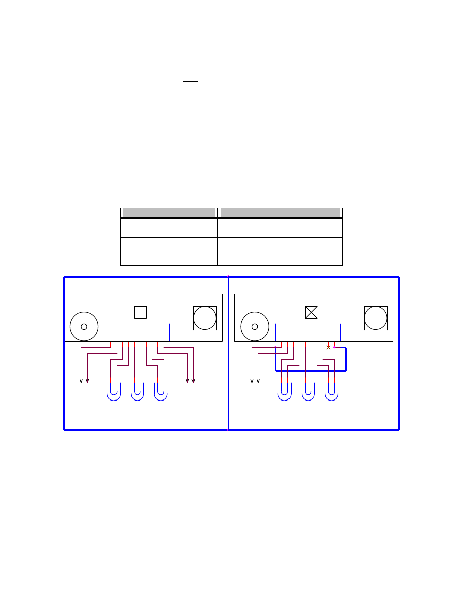
5.0 Pyro Channels and Wiring
NOTE: The low current or constant current mode of MC's Pyro Channels is intended for use with DaveyFire
N28B or Oxral
electric matches. Use of ANY other electric match device will most likely not work. When in
doubt, bench test using the G-Wiz FlightView software!!
When using the low current Pyro Channel mode with a single battery, you must install a jumper wire on the terminal block from pin 1 (Pyro
Battery (+)) to pin 10 (Computer Battery (+)). In this mode, a constant current of approximately 600mA will be supplied to any given Pyro Channel
under computer control.
When using the high current configuration (JP1 installed), you must use two separate batteries. One battery is connected to the terminal block
pins 1 and 2 (Pyro battery power). The second battery is connected to terminal block pins 9 and 10 (computer battery power). When using the high
current mode, be certain there is no jumper between terminal block pins 1 and 10! This prevents power to the computer from being
contaminated by glitches caused by Pyro Channel initiation. All of the Pyro Channel outputs are open drain outputs.
Terminal block pins 3, 5, and 7 are common. They are provided to ease the wiring of Pyro charges to the Flight Computer. The "-" (minus)
side of each Pyro Channel is connected to the drain of a high current, n-channel, power MOSFET. The MC's Pyro Channels are VERY stout and are
capable of collapsing the terminal voltage of a 9VDC battery close to 0 volts!
The ‘switch’ element on each of the three Pyro Channels is a high current, N-channel power MOSFET, wired in the open drain configuration.
Users with high current Pyro Channel requirements should consult Motorola's datasheet for the MTD3055VL and MTD20P03 devices. These are
the devices used to control events or devices connected to MC’s Pyro Channels. Contact G-Wiz Partners if you have higher current needs.
Pyro Channel #
Fires on Flight Event
1
Cluster or Staging (Air-start)
2
Apogee (minimum vertical velocity)
3
Low Altitude (400’ or 800' feet) or post
apogee timer (time value programmed by
the user with FlightView Software)
Squib 1
Squib 2
Squib 3
JP3
Terminal Block
1
2
3
4
5
6
7
8
9
10
Squib 1
Squib 3
Squib 2
JP3
Terminal Block
1
2
3
4
5
6
7
8
9
10
Low Current Pyro Configuration
(JP1 Removed)
G-Wiz MC
High Current Pyro Configuration
(JP1 Installed)
Pyro
Battery
Computer
Battery
JP1
+
+
-
-
G-Wiz MC
Computer/Pyro
Battery
JP1
+
-
REMOVE
Apogee
Low
Altitude
Cluster/
Stage
Low
Altitude
Cluster/
Stage
Apogee
6.0 Pyro Battery and Computer Battery
MC may be operated with one or two batteries. When MC is 'along for the ride' (e.g. motor ejection) and logging the altitude and flight profile
only, or MC is to initiate only low current electric matches (e.g. DaveyFire N28B or Oxral), a single 9 VDC battery may be connected to terminal
block pins 9 and 10. In this mode, you must connect a jumper wire from terminal block pin 10 to pin 1. The RISC processor must see valid

Revision: 1.1
5
computer and pyro power in order for the power-up check to complete properly.
When using multiple electric matches on any given channel or high current electric matches on ANY channel you MUST use the dual battery
configuration. In the dual-battery configuration, a 9 VDC battery is connected to power the computer and sensor on terminal block pins 9 and 10. A
second battery, 9 to 15 VDC is connected to terminal block pins 1 and 2. This battery provides all of the necessary current to initiate the attached
pyrotechnic devices.
On the G-Wiz MC, both CPU Battery and Pyro Battery are monitored for voltage level. The computer recognizes 2 levels of low-battery
voltage. At the first level, the status tone will change to a two-note warble. This warns that the battery is getting low, and should be changed soon.
If you hear this on the pad, or after prepping – don’t worry, you have at least one flight worth of power left (1-2 hours). The second level of low-
battery will cause the computer to repeat a two-tone fast. This is telling you to change the battery now. At this level, the computer will not perform
correctly until the battery is changed. No distinction is made between pyro and CPU battery, so you will have to determine this yourself by
changing one battery, or the other, and seeing if this makes the warble go away.
The first low battery point occurs at approximately 7 VDC, and the very low battery warning happens at approximately 6.5 VDC. On the pyro
battery, this assumes a 9 VDC battery. If a larger battery is connected, the battery warning may happen at a larger actual voltage, but the same
percentage of starting voltage. This is still very likely the extreme low end of usability for the battery.
7.0 Status LED, Beeper, and Arm LED
The Status LED has four functions: 1) Power-on and self-test results, 2) pyro and computer battery status, 3) Pyro Channel continuity status,
and 4) Peak barometric altitude flash-out.
7.1 Power-up and Battery Status
Upon application of battery power to the computer power pins of terminal block, the computer will emit a single long tone while it initializes
and tests its sensors for rational input levels. If it doesn’t see proper values from it’s sensors, the computer assumes there is a problem, and will start
emitting a fast two-note warble to indicate this failure. This is similar to the very low battery warble, except the Pyro port continuity will not be
tested and beeped out between warbles. This warble is continuous.
When initialization is complete, and if the computer passes the self-test, it will enter its ‘ready’ cycle. During this cycle, battery voltage is
sampled, and if OK, and single long beep and Status LED flash is emitted. If a low battery condition is detected, a warble is emitted as described
above. After the battery is tested, each Pyro port is tested for continuity as described below.
7.2 Continuity Status
The MC defines "good continuity" as a resistance value of less than thirty ohms (30
Ω
). If continuity tests 'good', a single flash of the Status
LED and a beep is emitted. If continuity is 'bad' a double beep/flash is emitted. The ports are tested sequentially starting from Pyro Channel 1
(cluster/stage) and ending with Pyro Channel 3 (low altitude event). The continuity state of each Pyro Channel is continuously beeped and flashed
out. Example: MC is connected to a fresh 9 VDC battery and has a single electric match connected to the apogee event (Pyro Channel 2). You would
hear/see the following repeating set of beeps or flashes: <long pause>, one short beep (battery OK), <short pause>, two beeps (cluster/stage event or
Pyro Channel 1 open), <short pause>, one beeps (apogee even or Pyro Channel 2 OK), <short pause>, two beeps (low altitude event or Pyro
Channel 3 open), <repeat pattern>. Since this is what you'd expect - launch it!
7.3 Altitude Readout
Upon launch detect, the Status LED remains extinguished during flight until approximately 5 seconds after landing. MC will commence
altitude readout, on the Status LED and beeper, after detecting landing. Digits are flashed out, in order, from most significant to least significant digit.
The number of flashes/beeps represents the digit (e.g. the number ‘7’ is represented by 7 flashes of the Status LED). A zero is one long 'on' or ‘beep’
period. There is a 2-second delay with the Status LED extinguished before the sequence repeats.
7.4 Arm LED
In normal operation of the MC, the rocketeer should NEVER see the Arm LED illuminate, unless bench testing is in
progress with an attached host computer. MC's pyro circuitry is specially designed for safety. No single failure on the MC
can result in a pyro channel being inadvertently fired. The pyro channels are NOT armed until a launch has been detected and
a specific flight event has occurred. When bench testing MC with an attached host computer (typically PC or Mac), the red
Armed LED will illuminate for ~1 second after the rocketeer commands a pyro channel to be fired from our FlightView
software. NOTE: If the Pyro Channel Inhibit/Safe Plug is installed in the mating J2/J6 jack on MC, electric
matches or squibs connected to the pyro channels can NOT be initiated or fired, regardless of the state of the
Armed LED.

Revision: 1.1
6
8.0 RS232 Host Computer Interface
The MC Flight Computer is provided with a ribbon cable terminated with a 10-pin header and 9-pin male subminiature D connector. The
ribbon cable 10-pin header mates with the MC Flight Computer 10-pin male header. Be certain to align the red stripe on the ribbon cable with
the “PIN 1” marking on the MC Flight Computer printed circuit board.
8.1 PC Interface
To connect the MC Flight Computer to your
PC
computer, you’ll need the following:
1) A free RS232 serial port on your computer and,
2) A 9-pin female subminiature D connector to 9-pin female subminiature D connector cable wired in the null modem configuration. The
null modem cable is also known as a “crossover cable”. These cables are readily available at most computer stores.
8.2 iMac Interface
To connect the MC Flight Computer to your
iMac or other Power Mac
computer, you’ll need the following:
1) Keyspan USB to RS232 serial converter (Keyspan USB PDA Adapter). Other units may work but have not been tested. The driver
software must be installed and working. You must make note of what the new serial port is named. The new port does NOT need to
emulate a MAC 'modem' or 'printer' port, though doing so is OK.
2) A 9-pin female subminiature D connector to 9-pin female subminiature D connector cable wired in the null modem configuration. The
null modem cable is also known as a “crossover cable”. These cables are readily available at most computer stores.
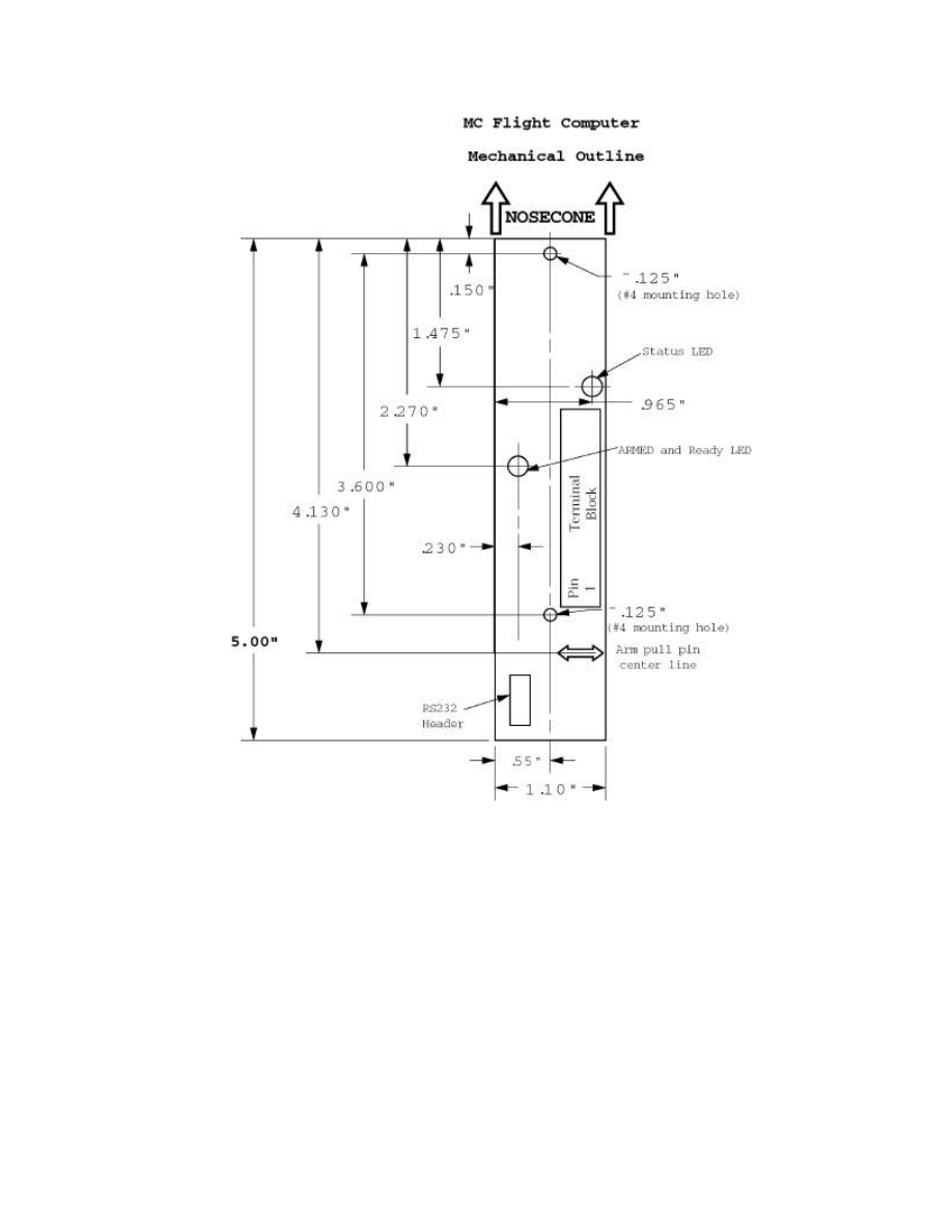
9.0 G-Wiz MC Mechanical Data
Your MC Flight Computer is designed to be mounted with #4 hardware. There are two mounting holes provided. When mounting MC in
your rocket, be certain to orient the beeper/serial port side of G-Wiz toward the aft or motor side of the rocket. MC will
not
operate unless oriented
in the correct direction (see figure below).
When installing G-Wiz MC into a rocket, it must be protected from the ejection gases produced by the Pyro charges. The gases are
corrosive, will damage the Flight Computer, and void your warranty. Install the Flight Computer in a separate compartment that is gas tight
from the ejection gases. The drawing below shows the key mechanical dimension and mounting orientation. All dimensions listed are in inches.
9.1
Installation
Several different mounting techniques may be used to mount your MC in the airframe of your rocket. For high performance, minimum diameter
birds, such as the Shadow Composites Raven, direct mounting to the airframe is recommended. For other avionics bays, you may want to mount
your MC to a removable 0.093" or 0.125" G10 plate. You'll also need to drill a vent hole to vent the avionics chamber to the atmosphere. This is
typically done with a 1/8" to 3/16" diameter hole. For maximum accuracy, the hole should be at least 1 body caliber behind the nosecone. Vent-hole
placement with an MC Flight Computer is much less critical than with other non-accelerometer-based altimeters. Batteries should be securely held in
place with non-skid foam and nylon tie wraps or battery holders with nylon tie wraps and/or electrical tape.
Rockets and avionics are inherently complex. It's important to understand ***ALL*** of the system details when integrating electronics with a
rocket (e.g. proper electric matches to use, electric match peak and average current draw, all-fire and no-fire ratings of electric match, battery current
capacity, peak available battery current, etc.)
Revision: 1.1
7

Revision: 1.1
8
10.0
Limited Warranty and Disclaimer
G-Wiz Partners warrants the G-Wiz MC Flight Computer to be free from defects in materials and workmanship and remain in working order for
a period of 180 days. If the unit fails to operate as specified, the unit will be repaired or replaced at the discretion of G-Wiz Partners, provided the
unit has not been damaged, modified, or serviced by anyone except for the manufacturer.
G-Wiz MC Flight Computers are sold as an experimental accessory only. Due to the nature of experimental electronic devices, especially when
used in experimental carriers such as rockets, the possibility of failure can never be totally removed. The owners, employees, vendors and
contractors of G-Wiz Partners shall not be liable for any special, incidental, or consequential damage or expense directly or indirectly arising from the
customer or anyone’s use, misuse, or inability to use this device either separately or in combination with other equipment or for personal injury or
loss or destruction of other property, for experiment failure, or for any other cause. It is up to the user, the experimenter, to use good judgment and
safe design practices and to properly pre-test the device for its intended performance in the intended vehicle. It is the user or experimenter’s
responsibility to assure the vehicle will perform in a safe manner and that all reasonable precautions are exercised to prevent injury or damage to
anyone or anything. WARNING: Do not use this device unless you completely understand and agree with all the above statements and conditions.
First time use of the G-Wiz MC Flight Computer signifies the user’s acceptance of these terms and conditions.
11.0
Contact G-Wiz Partners
Please see our web site at:
http://www.gwiz-partners.com
. Our web site has the latest versions of all of our User's Manuals, FlightView Software
updates, and email contact information.
Wyszukiwarka
Podobne podstrony:
blizzer generator pradu users manual
07 Altivar11 A EU users manual
linux mandrake 8 1 users manual 3zyndeyhqooqyui2gqfop2orb3fn25dkbzr4wei 3ZYNDEYHQOOQYUI2GQFOP2ORB3FN
pimpmyea com FuturoFX Users Manual
universal remote control 8 in 1 users manual 121714
MJoy16 C1 Users Manual v1
USERS MANUAL
07 Altivar11 A EU users manual
McIntosh MC 250 Service Manual
PANsound manual
als manual RZ5IUSXZX237ENPGWFIN Nieznany
hplj 5p 6p service manual vhnlwmi5rxab6ao6bivsrdhllvztpnnomgxi2ma vhnlwmi5rxab6ao6bivsrdhllvztpnnomg
BSAVA Manual of Rabbit Surgery Dentistry and Imaging
Okidata Okipage 14e Parts Manual
Bmw 01 94 Business Mid Radio Owners Manual
Manual Acer TravelMate 2430 US EN
więcej podobnych podstron