
N
CE 1949
SINCE 1949
SINCE 1949
F I F T Y Y E A R S O F
S U S
P E N S I O
N I N N O VAT IO
N
F I F T Y Y E A R S O F
S U S
P E N S I O
N I N N O VAT IO
N
2
INDEX
Page
OWNER’S INFORMATION ............................................................................................................................................................. 2
GENERAL SPECIFICATIONS ........................................................................................................................................................ 3
SPECIFIC MARZOCCHI TOOLS .................................................................................................................................................... 3
GENERAL RULES FOR A CORRECT OVERHAULING AND MAINTENANCE ............................................................................ 4
FAILURES, CAUSES AND REMEDIES ......................................................................................................................................... 4
RECOMMENDATIONS FOR USE .................................................................................................................................................. 4
INSTALLATION ............................................................................................................................................................................... 5
DISC BRAKE SYSTEM ASSEMBLY .............................................................................................................................................. 5
ADJUSTMENTS .............................................................................................................................................................................. 5
DISASSEMBLY ............................................................................................................................................................................... 6
DISASSEMBLY DIAGRAM ............................................................................................................................................................. 7
REASSEMBLY .............................................................................................................................................................................. 11
FORK EXPLODED VIEW ................................................................................................................................................... 15-16-17
The figures and descriptions in this pamphlet are provided as a guide.
We reserve the right to make changes to the products without notice in line with our policy of continuous improvement.
Always respect Nature when riding !
OWNER'S INFORMATION
IMPORTANT: Installing a Marzocchi suspension system is a very delicate operation that must be carried out with extreme care. These installation
and maintenance instructions are designed for experienced bicycle mechanics and must be followed exactly as written and
specified. Failure to precisely follow these instructions could cause damage to one or more components of the Marzocchi
suspension system. This damage may not be readily visible or apparent and could lead to unexpected failure on one or more
components of your suspension to such extent that the rider may loose control of the bicycle and suffer severe injury.
The responsibility of the owner
1) The Marzocchi suspension system is designed to absorb the shocks of an uneven road surface in order to give the rider more control over this
bicycle. It is not designed to absorb the forces generated by jumps or other acrobatic maneuvers. If you subject the Marzocchi suspension system
to repeated jumps or other acrobatic maneuvers, you could cause one or more of the components of the suspension system to unexpectedly
break, resulting in a loss of bicycle control and serious injury to the rider.
2) Some of the parts of the bicycle, such as the brakes, steering, tires, wheel assembly and shifters may not have been adjusted at the time the
Marzocchi suspension system was installed on the bicycle. Before you ride the bicycle, be sure all the parts of the bicycle were properly adjusted
and functioning properly.
3) All of the components of the suspension system must be correctly assembled and tightened exactly to the specified torque values. Periodically
check the torque of these components to insure that they are correct. Failure to properly assemble and tighten the components could cause one
or more of the components to unexpectedly break, resulting in a loss of bicycle control and serious injury to the rider.
4) There are obvious risks associated with mountain biking and other types of bicycle riding. Despite the use of all safety equipment for the bicycle
and the rider, either injuries or damages may occur. This is the responsibility of the rider. To reduce the risk of injury, all activities must be under
proper supervision and only after proper training and experience. Good physical condition of the rider and the good state of the bicycle are
essential to be a safe and successful rider.
5) Be sure to read and follow all the instructions and warnings which originally accompanied your bicycle. In addition, it is recommended for added
safety and protection while riding that a good quality bicycle helmet be worn and that other safety devices such as lights, reflectors, or reflective
clothing be used. Some cities and states may require the use of a helmet and other safety equipment. Follow all traffic rules and all other laws
about safety equipment and use your bicycle where you are permitted to ride.
6) For any further information you might need, please call or write to this addresses:
LARM
Via Ca’ dell’Orbo, 36 -
40055 Villanova di Castenaso (Bologna) - Italy
☎
++51/6053460 - Fax ++51/6053411
MSC CORPORATION USA
28231 Avenue Crocker - Unit 100
VALENCIA CA, 91355
☎
+1 (805) 257-6630 - Fax +1 (805) 257-6636
It is your responsibility to make sure the assembly instructions in this book are precisely followed.
Always ride safely and carefully.
3
GENERAL SPECIFICATIONS
• Special cross-country fork whose legs are damped by a differentiated system.
• The left leg is sprung by a mechanical coil spring system, whereas the right leg is sprung by a mechanical coil spring system and damped by
a hydraulic cartridge as well.
• Oversized 30 mm stanchions and full length guide bushings for superior rigidity.
• Parts subjected to friction are cooled and lubricated by a specially formulated oil.
• Spring pre-load adjustment (in both legs) and rebound damping (right leg only) controlled via external top mount adjusters.
• Stanchions designed with a special safety feature to eliminate any chance of the stanchions becoming separated from the crown.
• Brake cable support kit available on request.
• Stanchion protection standard.
Z2 ATOM BOMB - Z2 BAM Disc Brake
Steer tube: EASTON aluminum steer tubes available for 1 1/8” diameter in non threaded or in CrMo steel with variable butting. Several lengths
available in threaded or non threaded 1 1/8” and 1 1/4” diameters.
Crown: Forged and CNC-machined. BAM
❊
aluminum alloy.
Arch: Forged and CNC-machined “BAM” aluminum alloy.
Stanchions: EASTON aluminum with variable butting.
Sliders: Cast and CNC-machined “BAM” aluminum alloy. Left slider equipped with disc brake adapter (Z2 BAM D.B.).
Slider bushing: Full length guide bushing composed of a copper base and impregnated with an anti-friction coating.
Seals: Computer designed oil seals guarantee the highest quality seals available.
Oil: Specially formulated oil which eliminates foaming and viscosity breakdown while providing complete stiction-free performance.
Fork leg oil: type EBH 16 - SAE 7.5.
– Z2 ATOM BOMB: right leg 75 cc, left leg 85 cc.
– Z2 BAM: right leg 90 cc, left leg 100 cc.
❊
BAM: Bomber Aerospace Material.
Special alloy developed from aerospace material.
Z2 Alloy
Steer tube: EASTON aluminum steer tubes available for 1 1/8” diameter in non threaded or in CrMo steel with variable butting. Several lengths
available in threaded or non threaded 1 1/8” and 1 1/4” diameters.
Crown: Forged and CNC-machined. BAM
❊
aluminum alloy.
Arch: Forged and CNC-machined “BAM” aluminum alloy.
Stanchions: EASTON aluminum with variable butting.
Sliders: Cast and CNC-machined aluminum alloy. Left slider equipped with disc brake adapter.
Slider bushing: Full length guide bushing composed of a copper base and impregnated with a anti-friction coating.
Seals: Computer designed oil seals guarantee the highest quality seals available.
Oil: Specially formulated oil which eliminates foaming and viscosity breakdown while providing complete stiction-free performance.
Fork leg oil: type EBH 16 - SAE 7.5.
– right leg: cc 80.
– left leg: cc 90.
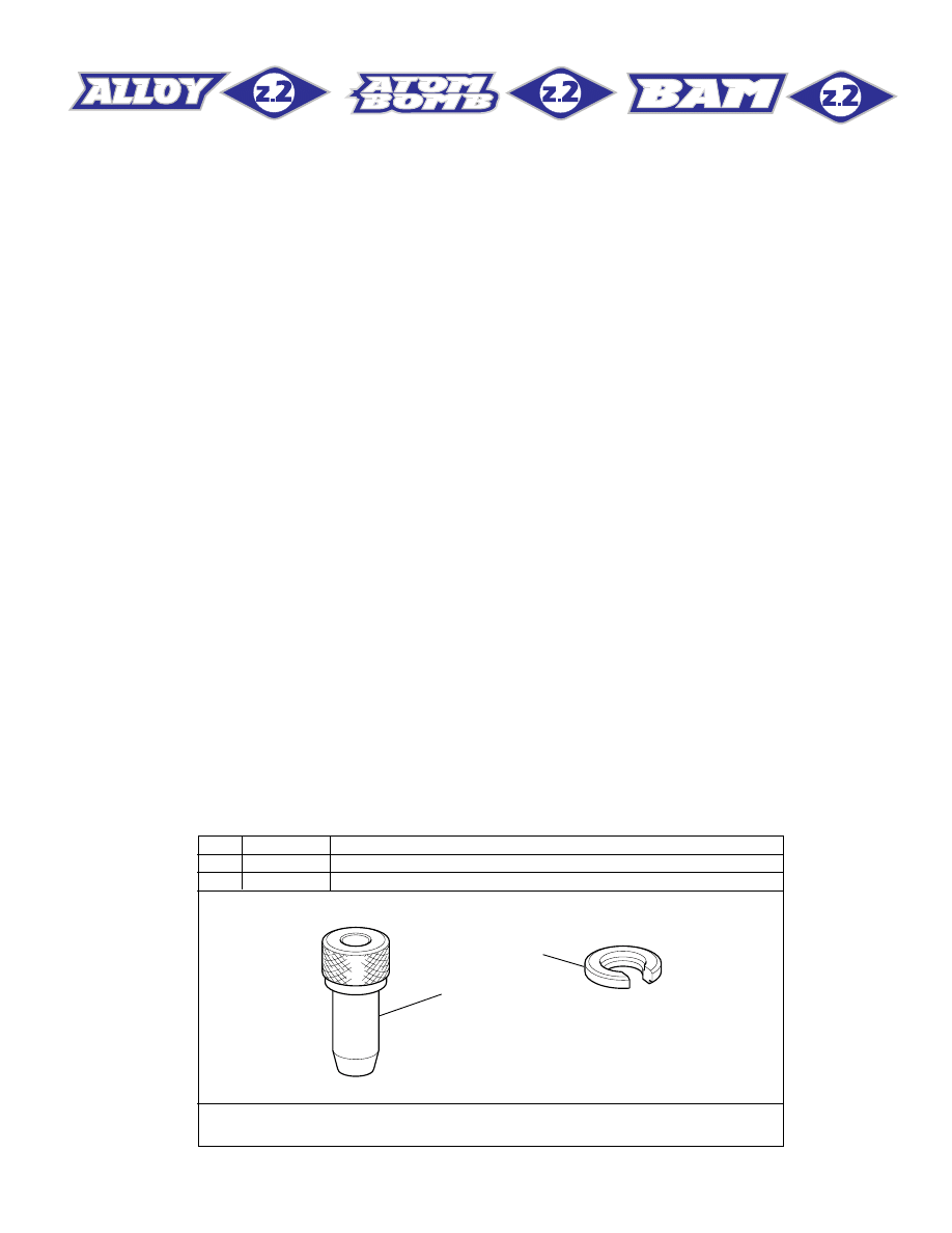
SPECIFIC MARZOCCHI TOOLS
B
A
Ref.
Item./Art.
Description and use
A
536003AB
Slider protector: to remove the oil seal from the slider
B
R 5068
Oil seal press: to press the oil seal into the slider
These are the specific tools necessary for an overhaul, you may find it necessary to use
common tools found in your shop.

4
Size:
– travel:
Z2 Alloy-Z2 ATOM BOMB = 65 mm (2.5 inches)
Z2 BAM = 80 mm (3.1 inches)
– crown to axle length:
Z2 Alloy-Z2 ATOM BOMB = 430 mm
Z2 BAM = 445 mm
– stanchions outer diameter: 30 mm
– fork leg distance between centers: 130 mm
– cantilever boss distance between centers: 80 mm
– pilot bushing length: 92 mm
This fork is supplied with:
– Warranty card
– Owners manual
– Technical Specifications.
GENERAL RULES FOR CORRECT OVERHAULING AND MAINTENANCE
1. Where specified, assemble and disassemble the shock absorption system only using the LARM or MARZOCCHI special tools, as shown in
the table below.
2. On reassembling the suspension system, always use new seals.
3. If two screws are close one to the other, always tighten using a 1-2-1 sequence. In short, screw the first screw just up to the point it is well
tightened, then tighten the second screw and then go back to the first one and screw it tighter.
4. Clean all metal parts with a special, preferably biodegradable solvent, such as trichloroethane or trichloroethylene.
5. Before reassembling, lubricate all parts in contact with each other using silicone fat spray.
6. Always grease the conic seal rings before reassembling.
7. Use wrenches with metric size only. Wrenches with inch size might damage the fastening devices even when their size is similar to that of the
wrenches in metric size.
FAILURES, CAUSES AND REMEDIES
This paragraph reports some failures that may occur when using the fork. It also indicates possible causes and suggests a remedy. Always refer
to this table before doing any repair work.
Excessive play of stanchions in
the sliders
Replace pilot bushings
Pilot bushings are worn
Replace hydraulic cartridge
Cartridge is faulty
Fork rebounds too fast even
though the adjuster is on the max.
damping position (right leg)
Fork has not been used for some
time and is locked out
Oil seals and dust seals tend to
stick to stanchion tube
Raise dust seal and lubricate stan-
chion tube, dust seal and oil seal
with silicone grease
Oil leaking through the bottom of
slider
O-ring on the cartridge seal nut
and/or pumping rod damaged
Replace the O-ring
REMEDIES
1. Replace oil seal
2. Replace oil seal and stanchion
tube
3. Clean the oil seal seat and re-
place it
FAILURES
CAUSES
1. Oil seal is worn out
2. Stanchion tube is scored
3. Excessive dirt on oil seal
Excessive oil build up on stan-
chions
RECOMMENDATIONS FOR MAINTENANCE
MARZOCCHI forks are based on advanced technology, supported by year-long experience in the field of professional mountain biking. In order
to achieve best results, we recommend to check and clean the area below the oil seal and the stanchion tube after each use and lubricate with
silicone oil.
Polished forks should be treated with bodywork polish at regular intervals in order to preserve their original finish.
5
INSTALLATION
Installing the BOMBER Z2 fork on a bicycle is a very delicate operation that should be carried out with extreme care. The installation should always
be checked by one of our Technical Service Centers.
WARNING: Steer tube/headset mounting and adjustment must be carried out in compliance with the headset manufacturer’s instructions
either when a threaded steer tube or an “A-Head Set” steer tube is installed. Improper installation may jeopardize the safety of the rider.
The steer tube is interchangeable in Z2 crown as it is secured to the crown by a clamp fastened with two screws. This allows the interchanging
of different diameters by using special reduction bushes. Steer tubes should be changed following installation instructions completely. Be sure
to install correct steer type (A-Head Set or threaded), diameter and length for the frame on which it should be fitted. If necessary check with one
of our Technical Service Centers for proper fit.
WARNING: In case of improper installation of the steer tube into the crown, the rider might lose control of his/her bicycle, thus jeopardizing
his/her safety.
Check the torque of the bolts fastening the stanchions to the crown and attaching the arch to the sliders. For recommended torque settings, see
the table below:
DISC BRAKE SYSTEM ASSEMBLY
Assembling the brake caliper onto the slider is a very delicate operation that should be carried out with extreme care. Improper assembly might
overstress the caliper supports which might break.
This system should be assembled by specialized technicians in a position to fully understand and properly follow the instructions given by the
manufacturer.
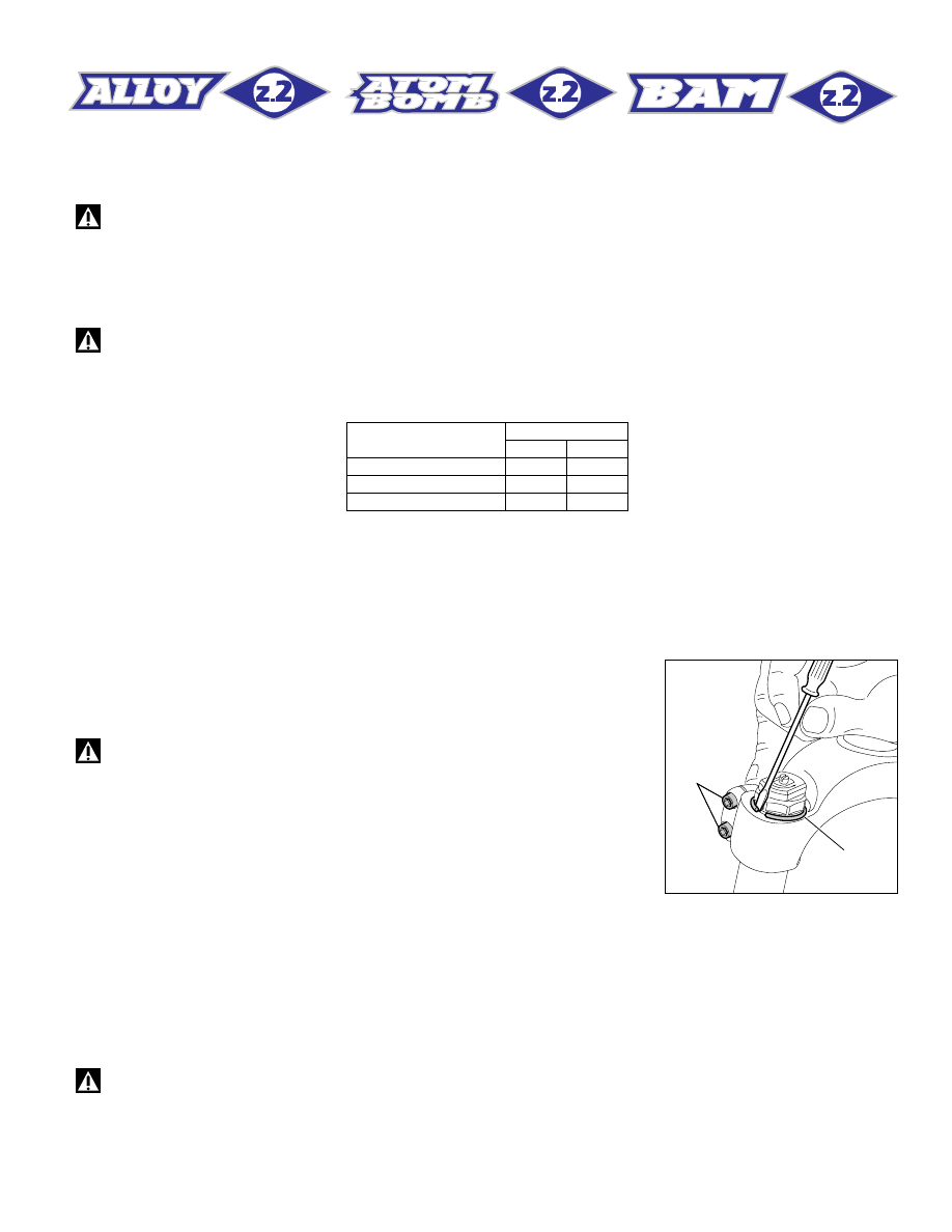
ADJUSTMENTS
IMPORTANT: both fork legs should be adjusted on the same position.
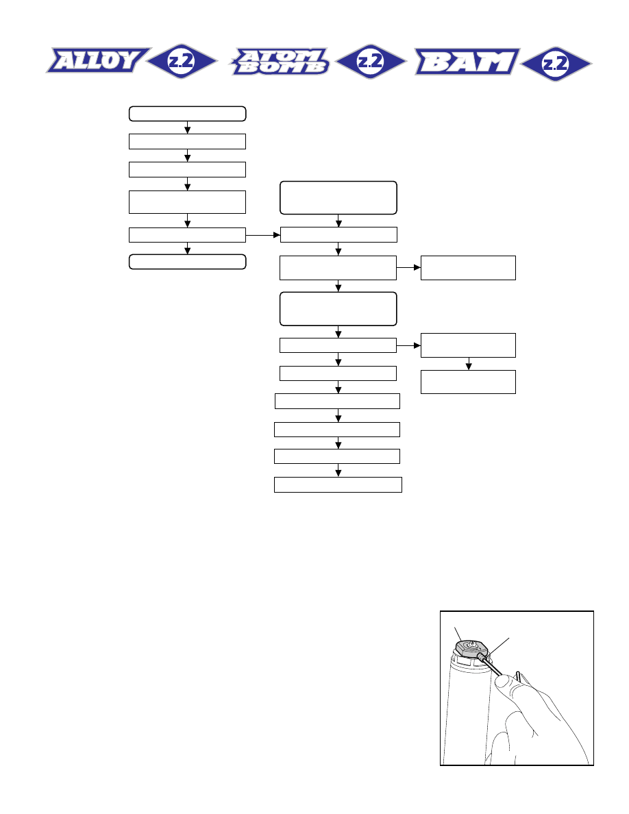
To remove the fork legs from the crown, loosen the bolts (32, FIG. A)
and remove the safety ring (1, FIG. A). For easier removal, insert a small
screwdriver between the ring and its seat and then remove the
complete fork legs.
WARNING: Be sure to install the fork legs safety rings when
reassembling, so that the fork legs do not become separated from the
crown even though the bolts have become loose.
32
1
32
1
FIG. A
Tightening torque
Thread diameter
Nm
lb ft
M4
4
2.9
M5
9
6.6
M6
11
7.5
6
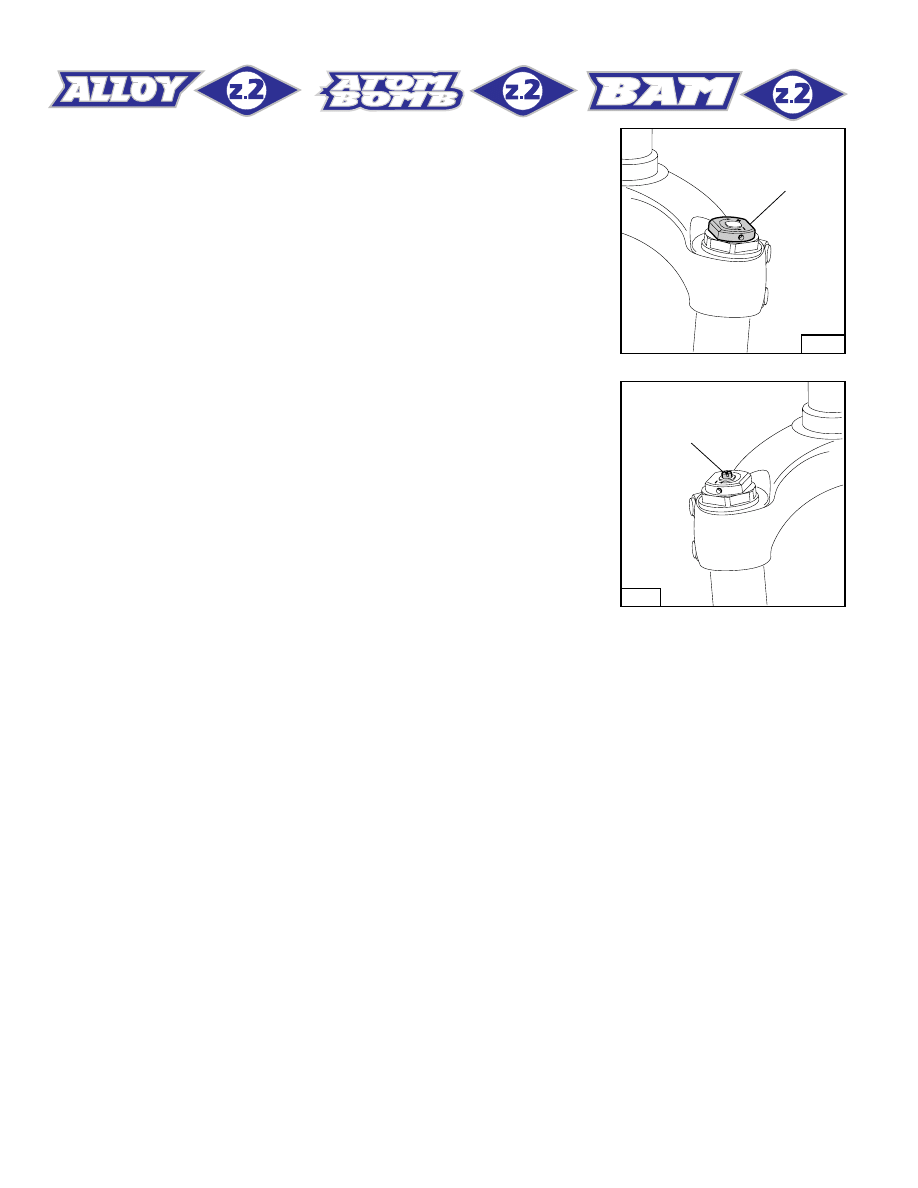
SPRING PRELOAD (FIG. B)
The spring preload determines COMPRESSION damping and can be
adjusted by turning the knob (2) on top of the fork legs. From the factory
the Z2 is set with the minimum preload, i.e. the adjustment knob is
completely unscrewed counterclockwise. However, the springs are
slightly preloaded to help counteract static loads. By turning the
adjustment knob clockwise, the preload is increased up to the maxi-
mum value equal to 15 mm’s of spring preload. This adjustment is
essential in order to have the right Z2 response for the rider’s weight
and riding style.
REBOUND & COMPRESSION
ADJUSTMENT (FIG. C)
The right fork leg is equipped with an adjuster screw (A) for damping.
When turning this adjuster clockwise into the cartridge rod, the damping
for compression & rebound increases. In short, the amount of adjust-
ment applied on the piston in the fluid determines the rate of compres-
sion & rebound damping. To adjust, always start from the minimum
damping setting, i.e. unscrew completely counterclockwise. Adjust-
ment range is about 8 turns – i.e. abt. 4 mm.
2
Left
FIG. B
A
Right
FIG. C
DISASSEMBLY
GENERAL
– The reference numbers given in this section relate to the components shown in the forks exploded view on page 15-16-17.
– These operations refer to the fork legs having already been removed from the crown and disassembled from the brake arch.
-– Before starting any operation, please read the diagram below. It shows the quickest procedure and the exact sequence in which it should be
disassembled. Locate the part you need to remove in the diagram, then look at the arrows to determine which other parts you will need to remove
first.
7
2
3
FIG. 1
SPRING CHANGE
PRELOAD KNOB FIG. 1
STOP RING FIG. 2
STANCHION TUBE CAP
FIG. 3
SPRING FIG. 4
FORK OIL CHANGE
HYDRAULIC
CARTRIDGE
CHANGE (right leg)
FOOT NUT FIG. 5
HYDRAULIC CARTRIDGE
FIG. 6
PILOT BUSHING AND
SEAL ASSEMBLY
CHANGE
STANCHION TUBE FIG. 7
DUST SEAL FIG. 9
STOP RING FIG. 10
OIL SEAL FIG. 11
UPPER WASHER FIG. 12
PILOT BUSHING FIG. 13
PUMPING ROD
FIG. 8
REBOUND STOP
RUBBER FIG. 8
REBOUND SPRING
FIG. 6
DISASSEMBLY DIAGRAM
SPRING CHANGE
FIG. 1
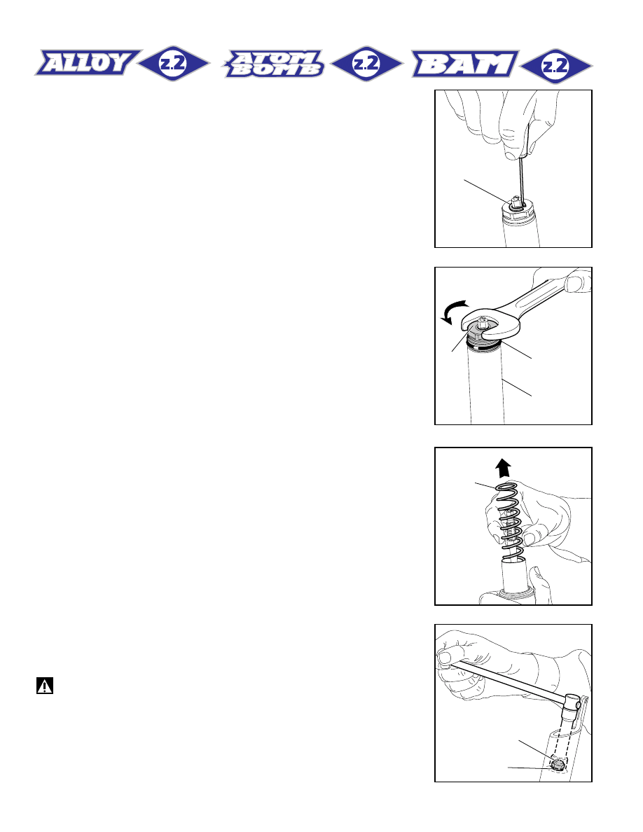
Move the knob (2) to the minimum preload position.
Loosen the small Allen bolt (3) fastening the preload knob by means of
a 1.5 mm Allen wrench. Remove the knob from the cap assembly.
8
22
21
4
5
6
13
9
FIG. 2
FIG. 5
FIG. 3
FIG. 4
FIG. 2
Remove the stop ring (4) from the top of the preload knob support with
a small screwdriver.
FIG. 3
Place the stanchion tube (13) in a vice making sure it is not damaged
or dented in the process and unscrew the cap (5) with a 26 mm open
end wrench.
Remove the cap complete with O-ring (6) from the stanchion tube.
FIG. 4
Push the stanchion tube into the slider and remove the spring (9).
Let all the oil drain into the fork leg. By following this procedure, there
is no need to check the oil level.
Make all necessary changes.
HYDRAULIC CARTRIDGE CHANGE
(right fork leg only)
FIG. 5
Let all the oil drain out.
WARNING: Remember to always recycle any used oil.
To change the fork leg oil follow the procedure as described in section
“REASSEMBLY” from FIG. 22 to FIG. 27.
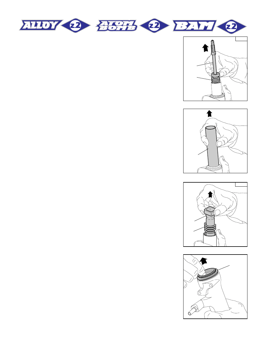
Turn the fork leg upside-down and unscrew the foot nut (22) complete
with O-ring (21) by the use of a 15 mm socket wrench.
9
Right
11
12
13
Left
36
12
14
FIG. 7
FIG. 6
FIG. 8
FIG. 9
FIG. 6
Pull the hydraulic cartridge (11) complete with rebound spring (12) out
of the stanchion tube.
Replace the whole hydraulic cartridge.
PILOT BUSHING AND SEAL ASSEMBLY CHANGE
FIG. 7
Pull the stanchion tube (13) completely out of the slider.
FIG. 8
A pumping rod (36) complete with rebound spring (12) is fitted into the
L.H. leg, inside the stanchion. Withdraw the above parts from the tube
top.
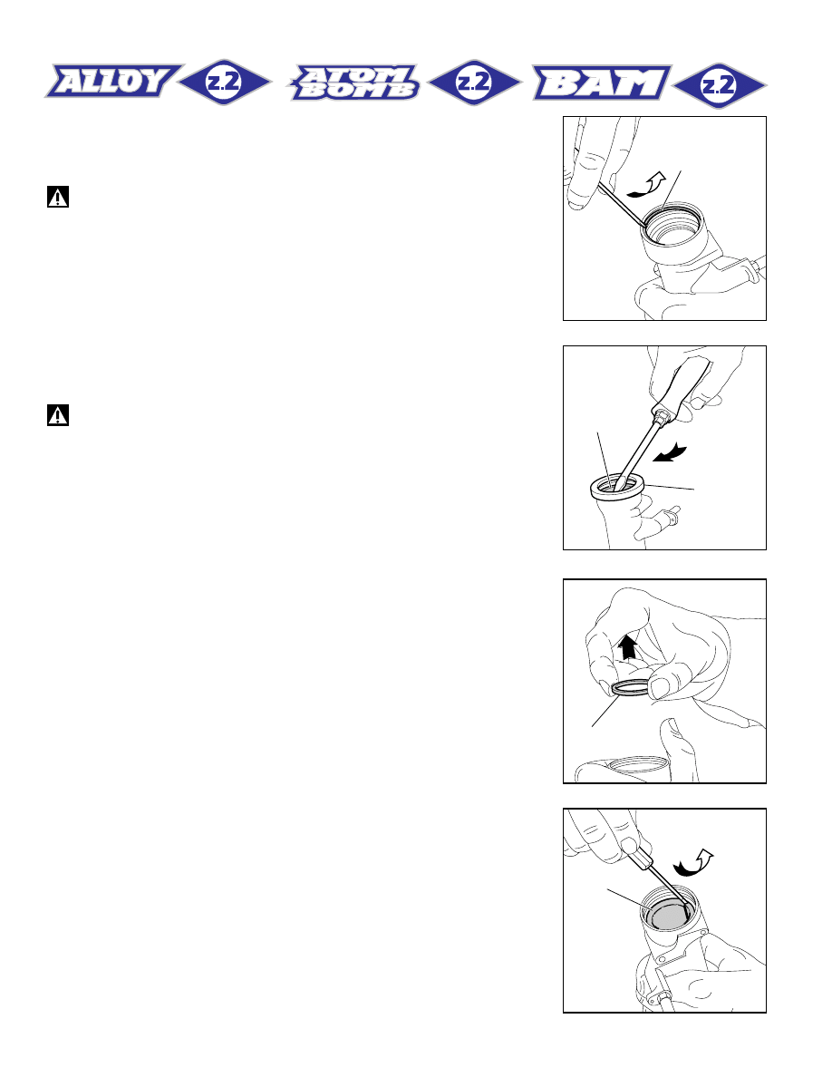
FIG. 9
Use a small screwdriver and remove the dust seal (14) from the slider.
10
15
16
A
17
18
FIG. 11
FIG. 10
FIG. 12
FIG. 13
FIG. 10
Remove the stop ring (15) from the slider by placing the screwdriver bit
in one of the openings on the stop ring and carefully lifting the ring out
of place.
IMPORTANT: when removing the stop ring, make sure not to
damage its seat.
FIG. 11
Fit the slider protector (A) onto the slider and remove the oil seal (16)
with the help of a large slot screwdriver.
IMPORTANT: when removing the oil seal, make sure not to
damage its seat. Once removed the oil seals should not be used again.
FIG. 12
Remove the upper washer (17) from the slider.
FIG. 13
Fit the bit of a small screwdriver into the upper edge slot of the pilot
bushing (18) and lift gently. Pull the bushing out of the slider and make
all necessary changes.
11
18
17
16
B
FIG. 14
FIG. 15
FIG. 16
REASSEMBLY
CAUTION: before reassembling, all metal parts should be washed
carefully with inflammable and biodegradable solvent and dried with
compressed air.
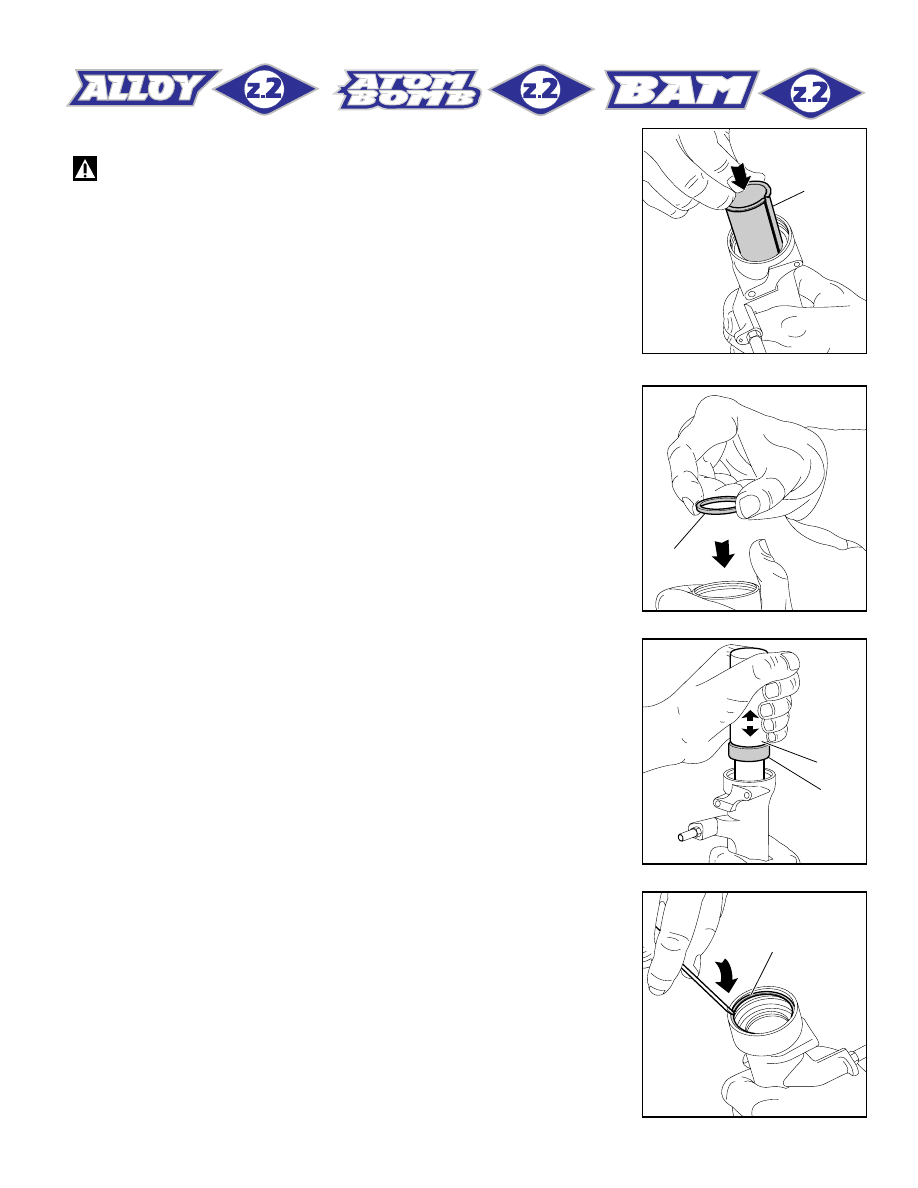
PILOT BUSHING AND SEAL ASSEMBLY
FIG. 14
Check that no dirt or debris is between slider and bushing. Insert the
pilot bushing (18) into place so that it adheres to the slider.
FIG. 15
Fit the upper washer (17) into the slider so that it touches the pilot
bushing.
FIG. 16
Lubricate the oil seal (16) and place it onto the seal press (B) with the
hollow side toward the slider.
Press the oil seal into place until it touches the lower washer by using
the above seal press.
15
FIG. 17
FIG. 17
Insert the stop ring (15) making sure it is properly seated into place.
12
14
13
Right
Left
12
11
36
12
22
21
Nm
12
FIG. 19
FIG. 18
FIG. 20
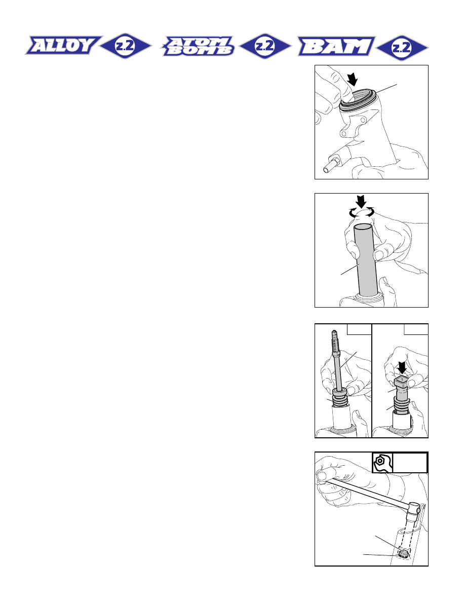
FIG. 18
Lubricate the dust seal (14) and fit it into the top of the slider.
STANCHION TUBE
FIG. 19
Fit the stanchion tube (13) gently into the dust seal, from the unthreaded
end. Rotate the stanchion tube while inserting it into the seal to facilitate
installation and reduce the chance of damaging the seals. Check to see
that the stanchion tube slides unrestricted by cycling the fork up and
down several times.
The tube should slide freely inside the seal assembly without any side
play.
In the event it is too hard or too soft, repeat the previous steps described
above and check components to ensure they are not damaged.
HYDRAULIC CARTRIDGE (right leg) AND PUMPING ROD (left leg)
FIG. 20
Push the stanchion up to slider bottom.
Fit the hydraulic cartridge (11) complete with the rebound spring into the
R.H. stanchion and push until it reaches the bottom. Fit the pumping rod
(36) complete with rebound spring (12) into the L.H. stanchion and push
to the bottom.
FIG. 21
Grease the O-ring (21) on the foot nut (22) and screw the nut on the
threaded end of both the hydraulic cartridge and the pumping rod.
Tighten at 12 Nm.
Check to verify that the stanchion tube slides properly through the
stroke by pumping it up and down several times.
FIG. 21
13
H
H (mm)
40 Right - 45 Left
37
Z2 BAM
Z2 ATOM BOMB
37
Z2 Alloy
Right
9
10
Right
5
6
8
11
5
Nm
12
FIG. 23
FIG. 22
FIG. 24
FIG. 25
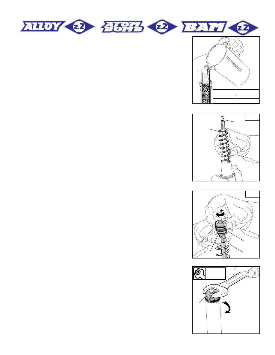
HOW TO FILL WITH OIL
FIG. 22
Pour the oil little by little when the stanchion tube is fully down and then
pump with the cartridge (11) rod so as to have a better filling. Cartridge
is full when no air is detected when pumping, in the completely closed
position. Check that oil level is at the recommended distance (H) from
the top of the stanchion tube.
SPRING AND CAP
FIG. 23
Fit the spring (9) into the stanchion tube.
Move the preload adjuster (7), in the cap, to the minimum preload
position.
Lubricate the O-ring (10) on the top of the preload knob support (right
slider only) and the O-ring (6) on the cap (5).
FIG. 24 (right leg only)
Screw the cap (5) complete with preload adjuster (7) and lower washer
(8) onto the cartridge (11) rod. Screw cap all the way in.
FIG. 25
Take the stanchion tube and fit the cap (5) by hand. Place the stanchion
tube in a vice making sure it is not damaged or dented in the process.
Tighten the cap at 12 Nm.
14
4
Nm
1,5
2
3
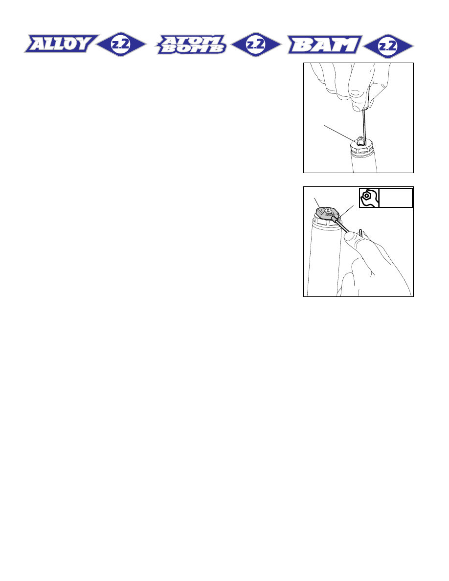
FIG. 27
FIG. 26
FIG. 26
Fit the stop ring (4) of the preload knob support and make sure it is
properly seated into place.
FIG. 27
Fit the preload knob (2) and secure it on the support by tightening the
Allen bolt (3) at 1.5 Nm.
At this point the brake arch can be assembled with the fork legs, which
should be fitted onto the crown as specified in section “INSTALLA-
TION”.
15
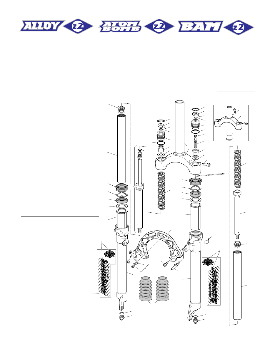
FORK EXPLODED VIEW
Ref.
Description
1
Safety ring
2
Preload knob
3
Allen bolt
4
Stop ring
5
Cap
6
O-ring
7
External preload adjuster
8
Lower washer
9
Spring
10
O-ring
11
Hydraulic cartridge
12
Rebound spring
13
Stanchion tube
14
Dust seal
15
Stop ring
16
Oil seal
17
Upper washer
18
Pilot bushing
19
R.H. slider
20
L.H. slider
21
O-ring
22
Foot nut
23
Cantilever boss
24
Arch
25
Screw
26
Brake cable support
27
Screw
28
Brake cable support kit
29
R.H. sticker
30
L.H. sticker
31
Crown with steer tube
32
Screw
33
Crown
34
Steer tube
35
Internal preload adjuster
36
Pumping rod
37
Stanchion protections
38
Sticker
32
33
34
32
12
13
6
14
15
16
17
18
19
22
21
22
21
1
2
7
8
9
9
36
12
13
14
15
16
17
18
20
25
23
37
24
26
28
27
3
4
4
5
1
2
7
35
10
32
38
31
3
5
6
8
11
10
30
29
Z2 ATOM BOMB
16
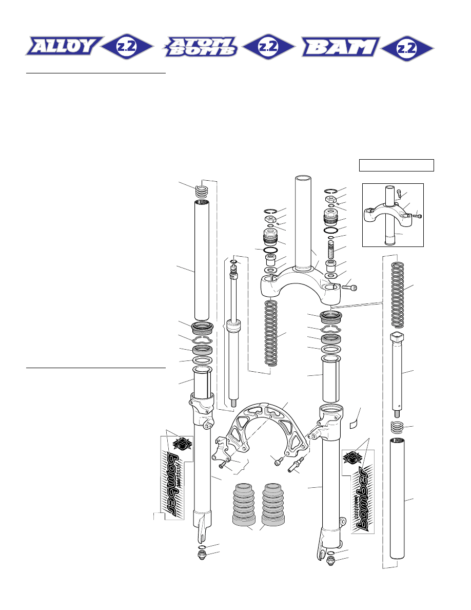
Ref.
Description
1
Safety ring
2
Preload knob
3
Allen bolt
4
Stop ring
5
Cap
6
O-ring
7
External preload adjuster
8
Lower washer
9
Spring
10
O-ring
11
Hydraulic cartridge
12
Rebound spring
13
Stanchion tube
14
Dust seal
15
Stop ring
16
Oil seal
17
Upper washer
18
Pilot bushing
19
R.H. slider
20
L.H. slider
21
O-ring
22
Foot nut
23
Cantilever boss
24
Arch
25
Screw
26
Brake cable support
27
Screw
28
Brake cable support kit
29
R.H. sticker
30
L.H. sticker
31
Crown with steer tube
32
Screw
33
Crown
34
Steer tube
35
Internal preload adjuster
36
Pumping element
37
Stanchion protections
38
Sticker
32
33
34
32
38
30
29
12
13
6
14
15
16
17
18
19
22
21
22
21
1
2
7
8
9
9
36
12
13
14
15
16
17
18
20
25
23
37
24
26
28
27
3
4
4
5
1
2
7
35
10
32
31
3
5
6
8
11
10
Z2 BAM Disc Brake
17
32
33
34
32
12
13
10
6
14
15
16
17
18
19
22
21
22
21
1
2
7
8
9
9
36
12
38
13
14
15
16
17
18
20
25
23
37
24
26
28
27
3
4
4
5
1
2
7
35
10
32
31
3
5
6
8
11
30
29
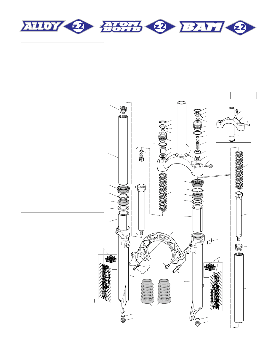
Z2 Alloy
Ref.
Description
1
Safety ring
2
Preload knob
3
Allen bolt
4
Stop ring
5
Cap
6
O-ring
7
External preload adjuster
8
Lower washer
9
Spring
10
O-ring
11
Hydraulic cartridge
12
Rebound spring
13
Stanchion tube
14
Dust seal
15
Stop ring
16
Oil seal
17
Upper washer
18
Pilot bushing
19
R.H. slider
20
L.H. slider
21
O-ring
22
Foot nut
23
Cantilever boss
24
Arch
25
Screw
26
Brake cable support
27
Screw
28
Brake cable support kit
29
R.H. sticker
30
L.H. sticker
31
Crown with steer tube
32
Screw
33
Crown
34
Steer tube
35
Internal preload adjuster
36
Pumping element
37
Stanchion protections
38
Sticker
Wyszukiwarka
Podobne podstrony:
1999 z2 bam parts list
1998 z2 bam
1999 z1 bam 100mm parts list
1999 z2 superfly
1999 z1 bam 130mm parts list
1999 z1 bam alloy
1999 z2 light parts list
1999 z2 super fly parts list
1999 z2 superfly
PiU P Z2
Ustawa z dnia 25 06 1999 r o świadcz pien z ubezp społ w razie choroby i macierz
brzuch 1999 2000
zegarmistrz 731[05] z2 02 u
chojnicki 1999 20 problemy GP
711[04] Z2 04 Wykonywanie konse Nieznany (2)
mechanik operator pojazdow i maszyn rolniczych 723[03] z2 04 n
fototechnik 313[01] z2 04 n
monter instalacji gazowych 713[07] z2 03 u
więcej podobnych podstron