6 6 • J A N U A R Y 2 0 0 5 • E L E C T R O N I C S F O R Y O U
W W W . E F Y M A G . C O M
C
M
Y
K
C
M
Y
K
CONSTRUCTION
I
n most applications, a
microcontroller can satisfy all the
system requirements with no ad-
ditional integrated circuits. Due to
their low cost and a high degree of
flexibility, microcontrollers are finding
way into many applications that were
previously accomplished by mechani-
cal means or combinational logic. One
such application is a real-time clock.
Here’s a real-time clock using
Atmel AT89S8252. The software for the
microcontroller is written in BASCOM-
51 (a powerful BASIC Compiler),
which is capable of creating a hex file.
The hex file code can be burnt into the
microcontroller using any commonly
available programmer or kit.
IC AT89S8252 is a low-power,
high-performance CMOS 8-bit
microcontroller. It is manufactured us-
ing Atmel’s high-density nonvolatile
memory technology and is compatible
with the industry-standard 80C51 in-
struction set and pin-out. The power-
ful AT89S8252 microcontroller pro-
vides a highly flexible and cost-effec-
tive solution to many embedded con-
trol applications. Its main features are:
1. Compatible with MCS-51 prod-
ucts
2. 8kB in-system reprogrammable
downloadable Flash memory with SPI
serial interface for program download-
ing and endurance of 1000 write/erase
cycles
3. 2kB EEPROM with endurance of
100,000 write/erase cycles
4. 4V–6V operating range
5. Fully static operation: 0 Hz to
24 MHz
6. Three-level program memory
lock
7. 256×8-bit internal RAM
8. 32 programmable I/O lines
9. Three 16-bit timer/counters
10. Nine interrupt sources
11. Programmable UART serial
channel
12. SPI serial interface
13. Low-power idle and
power-down modes
14. Interrupt recovery
from power-down
15. Programmable
watchdog timer
16. Dual data pointer
17. Power-off flag
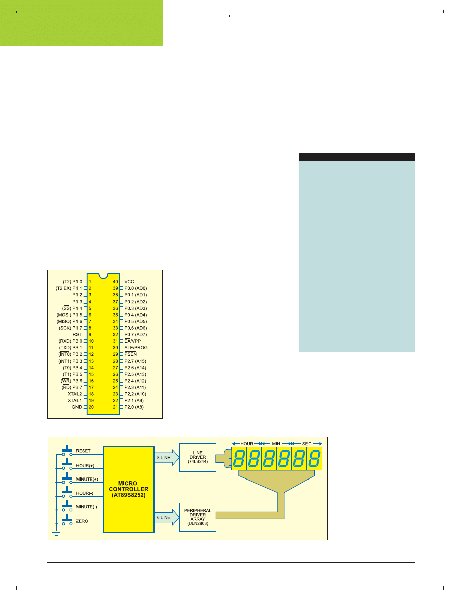
Fig. 1
shows the pin as-
signments of AT89S8252.
Fig. 2
shows the block
diagram of the real-time
clock using AT89S8252
microcontroller and a few
n
K.S. SANKER
MICROCONTROLLER-BASED
REAL TIME CLOCK
Semiconductors:
IC1
- 7805 5V regulator
IC2
- AT89S8252
microcontroller
IC3
- 74LS244 octal line
driver
IC4
- ULN2803 octal
transistor array
DIS1-DIS6
- LTS543 common-
cathode 7-segment
display
LED1
- Red LED
Resistors (all ¼-watt, ±5% carbon, unless men-
tioned otherwise):
R1
- 1-kilo-ohm
R2
- 10-kilo-ohm
R3-R11
- 100-ohm
Capacitors:
C1
- 100µF, 25V electrolytic
C2
- 0.1µF ceramic
C3, C4
- 22pF ceramic
C5
- 10µF, 10V electrolytic
Miscellaneous:
X
TAL
- 6MHz crystal
S1-S6
- Push-to-on switch
PARTS LIST
Fig. 1: Pin assignments of AT89S8252
Fig. 2: Block diagram of real-time clock using AT89S8252 microcontroller
6 8 • J A N U A R Y 2 0 0 5 • E L E C T R O N I C S F O R Y O U
W W W . E F Y M A G . C O M
C
M
Y
K
C
M
Y
K
CONSTRUCTION
external components to display the
time in HH.MM.SS format on six 7-
segment displays. Switches S2, S3, S4
and S5 are used for hour increment,
minute increment, hour decrement and
minute decrement, respectively, while
switch S6 is used for resetting the clock
display to all zeroes.
Out of the three ports of the
microcontroller, one port is used for
setting the time and the other two
ports are used for displaying the time.
Line driver and Darlington driver
array are used to drive the segment
data and enable the 7-segment display,
respectively.
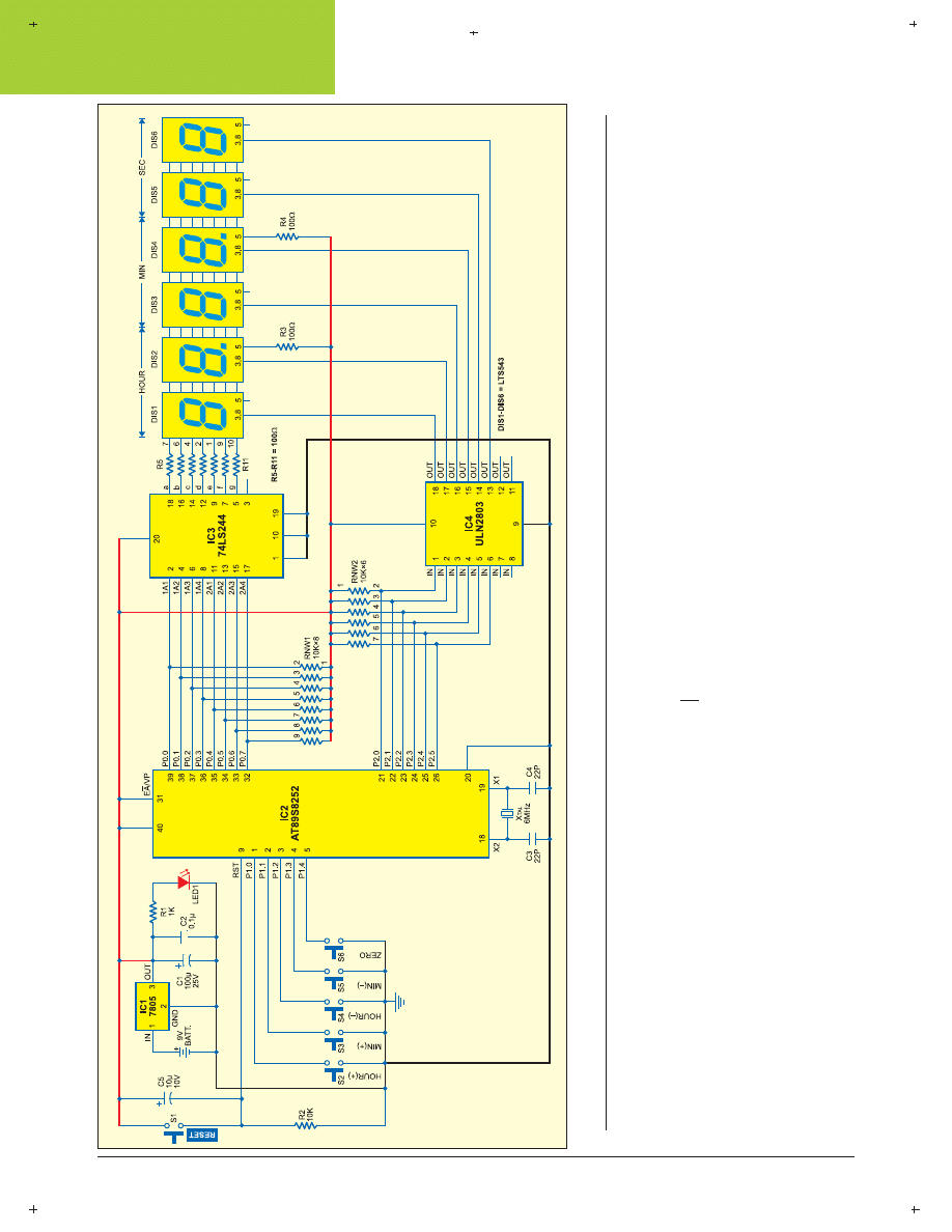
Circuit description
Fig. 3
shows the circuit of the real-time
clock built around AT89S8252
microcontroller (IC2). The power sup-
ply from the 9V battery is down con-
verted and regulated by IC 7805 (IC1)
to provide regulated 5V to the circuit.
Glowing of LED1 indicates that power
to the circuit is switched on. Resistor
R1 acts as the current limiter.
Switch S1 is used to manually re-
set the microcontroller, while the
power-on reset signal for the
microcontroller is derived from the
combination of capacitor C5 and re-
sistor R2. EA/Vpp pin (pin 31) of the
microcontroller is connected to Vcc to
enable internal program execution.
Pins 19 and 18 are input and output
pins respectively, of the built-in
inverting amplifier, which can be
configured for use as an on-chip oscil-
lator. A 6MHz crystal is used to gen-
erate the clock frequency for the
microcontroller.
IC AT89S8252 has four bidirectional
8-bit ports, of which only three ports (0
through 2) have been used in this cir-
cuit. Port 0 is an 8-bit open drain bidi-
rectional I/O port. As an output port,
each pin can sink eight TTL inputs.
Port 0 can also be configured as the
multiplexed low-order address/data
bus during accesses to the external pro-
gram and data memory. External pull-
ups are required during data outputs.
Port 0 is used to drive the segments
of all the 7-segment common-cathode
displays. Pin 1 of the RNW1 resistor
network is connected to Vcc and pins
Fig. 3: Circuit of the real-time clock built around AT89S8252 microcontroller
7 0 • J A N U A R Y 2 0 0 5 • E L E C T R O N I C S F O R Y O U
W W W . E F Y M A G . C O M
C
M
Y
K
C
M
Y
K
CONSTRUCTION
2 through 9 are connected to port-0
pins 39 down through 32 of IC1 as ex-
ternal pull-ups. Pins 39 down through
32 of port 0 are also connected to the
input pins of octal line driver IC
74LS244 (IC3).
Segments ‘a’ through ‘g’ of 7-seg-
ment displays DIS1 through DIS6 are
joined and connected to the output
pins of IC3 via resistors R5 through
R11, respectively. IC3 acts as an octal
buffer between the microcontroller and
the displays to increase the current
level. Resistors R5 through R11 limit
the current through the 7-segment dis-
plays. Each display comprises seven
light emitting diodes with their com-
mon cathodes connected together, and
hence termed as the common-cathode,
7-segment display.
Port 2 acts as the multiplexer to
select a particular 7-segment display
using octal Darlington transistor array
ULN2803 (IC4). Pins 21 through 26 of
port 2 are pulled up by the RNW-2
resistor network and also connected to
pins 1 through 6 of IC4. IC4 outputs a
low signal to light up the segments of
the 7-segment display selected by the
port-2 data.
Ports 0 and 2 provide the segment
data and enable signal simultaneously
for displaying a particular number on
the 7-segment display. Decimal point
pin 5 of displays DIS2 and DIS4 is en-
abled by Vcc through resistors R3 and
R4, respectively, to differentiate the
hour, minute and second.
Port 1 detects pressing of the
switches to increment/decrement
hours and minutes and reset the dis-
play to 00:00:00 by pulling the port
pins to ground. The software detects
pressing of the switches and sets the
time accordingly. Pull-up resistors on
port 1 have been avoided since the port
already has internal pull-ups.
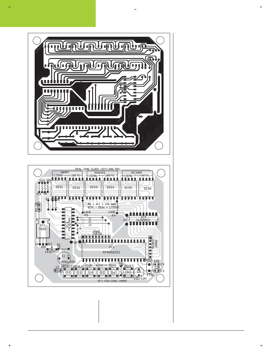
An actual-size, single-side PCB for
the real-time clock is shown in Fig. 4
and its component layout in Fig. 5.
Software
The software for the real-time clock is
written in Bascom51 version. Those
who have knowledge of Basic, Basic-
A, GW-Basic or QBasic language (used
to run on the good old 286 and 386
PCs with DOS 2.x to 6.2) will under-
stand the program easily. The demo
version of Bascom-8051 is available
on Website ‘www.mcselec.com/
download_8051.htm.’
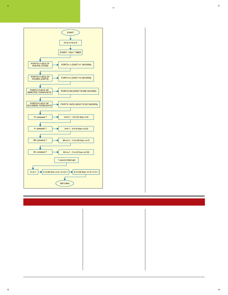
Fig. 6
shows the flow-chart of the
program. Step-wise explanation of
how the program works is given
below:
1. Define the port pins and where
Fig. 4: Actual-size, single-side PCB for the real-time clock
Fig. 5: Component layout for the PCB
7 2 • J A N U A R Y 2 0 0 5 • E L E C T R O N I C S F O R Y O U
W W W . E F Y M A G . C O M
C
M
Y
K
C
M
Y
K
CONSTRUCTION
they are connected.
2. Include the header
file for the
microcontroller.
3. Define the crystal
speed.
4. Declare the vari-
ables as bits, bytes and
words.
5. Initialise all ports
to 0, except port 1, which
is turned high to act as
an input port.
6. Run a diagnostic
subroutine to test the
segments of all the dig-
its.
7. Configure the in-
ternal timer as an inter-
rupt generator to get a
o n e - s e c o n d - a c t i v i t y
source.
8. Initialise hours,
minutes and seconds
variables to zero.
9. Get into a per-
petual Do loop to dis-
play the time in
HH:MM:SS format.
(Since there are no BCD-
to-7-segment converter
ICs and no latch ICs, it
is up to the software to
show the clock display
without being inter-
rupted.)
10. Set the input
switches to activate the
respective sub-routines
using the built-in command of
Bascom’s key debounce statement.
11. Check when seconds, minutes
and hours variables exceed their lim-
its and increment them accordingly.
12. Activate the digits one-by-one
through port 2 and show the corre-
sponding number on the display us-
ing port 0.
13. Declare subroutines for detec-
tion of the switches pressed to adjust
hours and minutes.
14. The
main display subroutine.
Since we have not used a 7-segment
converter IC, a quick table check us-
ing read and data concept in Basic is
performed to get the correct byte value
for the digit to be displayed.
15. The
internal timer interrupt
subroutine. This subroutine is called
2000 times in a second using a 6MHz
crystal and to generate an accurate
one-second variable, we set the flag
only once every 2000 times. This vari-
able is used to detect the seconds
change and increment the time in the
main Do loop routine. The accuracy
of the clock depends on the timer sub-
routine.
EFY note.
The source code and
other relevant files of this article have
been included in this month’s EFY-CD.
Other possible uses
The circuit and the software can be im-
proved to convert this real-time clock
into an alarm clock. With port 3 acti-
vated, it can be used as a multichan-
nel industrial timer.
Fig. 6: Flow-chart of the program
EFYCLK11.BAS
'--------------------------------------------------------------
' EFYclk.bas 18-10-04
' REAL TIME CLOCK DISPLAY ON six 7-SEG DIS-
PLAYS
' BY k.s.sankar www.mostek.biz for EFY
' written using BASCOM-51 from MSC electronics
Netherlands
'--------------------------------------------------------------
'Connect common cathode LED displays as follow-
ing :
' port-0 (red)
'a = P0.0
'b = P0.1
'c = P0.2
'd = P0.3
'e = P0.4
'f = P0.5
'g = P0.6
'dp= p0.7
'
'88 88 88
'hh mm ss port-2 (green) p2.0 /1 : 2/3 : 4/5
'12 34 56 digit number
' yellow port-1 set switches
'P1.0=H+ P1.1=H-
'P1.2=M+ P1.3=M-
'P1.4= 00 00 00 ( reset to 00 00 00)
'--------------------------------------------------------------
$regfile = "89s8252.dat"
$crystal = 6000000
'6 mhz crstal
Dim Once_a_sec As Bit
Dim Clock_word As Word
Dim Hours As Byte , Minutes As Byte , Seconds As
Byte
Dim Red As Byte , Green As Byte
Dim Count As Byte , X As Byte , Segment As Byte
Dim Number As Byte , Digit_select As Byte
Dim Del As Byte , Diagdelay As Byte
Dim Large As Word
Del = 1
' delay variable in milliseconds
' all ports 0
P0 = 0
'red
P1 = 255
'yellow all high for sw inputs
P2 = 0
'green
P3 = 0
'blue not used
Config Debounce = 30
' key debounce time in milli seconds
Config Timer0 = Timer , Gate = Internal , Mode = 2
'Timer0 use timer 0
'Gate = Internal no external interrupt
'Mode = 2 8 bit auto reload
Gosub Diag
' diagnostic routine
' set t0 internal interrupt
On Timer0 Timer_0_int
Load Timer0 , 250
Priority Set Timer0
Enable Interrupts
Enable Timer0
Start Timer0
Hours = 0
Minutes = 0

7 4 • J A N U A R Y 2 0 0 5 • E L E C T R O N I C S F O R Y O U
W W W . E F Y M A G . C O M
C
M
Y
K
C
M
Y
K
CONSTRUCTION
Seconds = 0
Clock_word = 0
Do
' yellow port-1 key inputs for setting
Debounce P1.0 , 0 , Hup , Sub
Debounce P1.1 , 0 , Hdown , Sub
Debounce P1.2 , 0 , Mup , Sub
Debounce P1.3 , 0 , Mdown , Sub
Debounce P1.4 , 0 , Zero , Sub
If Once_a_sec = 1 Then
' once_a_sec=calculation every second
Once_a_sec = 0
'update hh mm ss
inc seconds
If Seconds = 60 Then
Seconds = 0
inc minutes
If Minutes = 60 Then
Minutes = 0
inc hours
If Hours = 24 Then
Hours = 0
End If
End If
End If
End If
' display time constantly
' hours
Number = Hours / 10
P2 = 1
Gosub Disp
Waitms Del
P0 = 0
'-------
Number = Hours Mod 10
P2 = 2
Gosub Disp
Waitms Del
P0 = 0
'-------
'minutes
Number = Minutes / 10
P2 = 4
Gosub Disp
Waitms Del
P0 = 0
'-------
Number = Minutes Mod 10
P2 = 8
Gosub Disp
Waitms Del
P0 = 0
'-------
'SECONDS
Number = Seconds / 10
P2 = 16
Gosub Disp
Waitms Del
P0 = 0
'-------
Number = Seconds Mod 10
P2 = 32
Gosub Disp
Waitms Del
P0 = 0
'-------
Loop
' - - - - - - - - - - - - - - - - - -
' set keys below
Hup:
Incr Hours
If Hours >= 24 Then
Hours = 0
End If
Return
Hdown:
Decr Hours
If Hours = 255 Then
Hours = 23
End If
Return
Mup:
Incr Minutes
If Minutes >= 60 Then
Minutes = 0
End If
Return
Mdown:
Decr Minutes
If Minutes = 255 Then
Minutes = 59
End If
Return
Zero:
Hours = 0 : Minutes = 0 : Seconds = 0
Return
' - - - - - - - - -- - - - - - - -- - - - - -
Diag:
'diagnostics
'if zero button pressed then goto zero label and return
Diagdelay = 121
For Seconds = 1 To 5
Diagdelay = Diagdelay - 20
P2 = 1
For Green = 0 To 5
P0 = 1
For Red = 0 To 7
Debounce P1.4 , 0 , Zero
Waitms Diagdelay
Rotate P0 , Left
Next Red
Rotate P2 , Left
Next Green
Next Seconds
' next diag show 000000 to 999999 on all digits
' - - - - - - - -- - - - - -- - - - - - - -- - - -
For Number = 0 To 9
P2 = 1
For Large = 1 To 50
' approx 1 second time loop with 200 in large
For Green = 0 To 5
Debounce P1.4 , 0 , Zero
Gosub Disp
Waitms Del
Rotate P2 , Left
Next Green
Next Large
Next Number
Return
'Displaying routine
Disp:
Restore Tabela
' scan 7-seg table to get byte for the digit to display
For X = 0 To 9
Read Segment
If X = Number Then
'if X = value to display
P0 = Segment
'then set this value to Port0-red
Exit For
'and exit FOR loop
End If
Next
Return
' int subroutine -----------------
Timer_0_int:
Incr Clock_word
If Clock_word > 2000 Then
Clock_word = 0
Once_a_sec = 1
End If
Return
'---- data for 7-seg LED display ------
Tabela:
Data 63 , 6 , 91 , 79 , 102 , 109 , 125 , 7 , 127 , 111
' end of program
' -=-=-=-=-=-=-=-=-=-=-=-=-=-=-=-=-=
Advert
Wyszukiwarka
Podobne podstrony:
8051 clock article
efy fm proof article
8051 CLOCK SCH1
8051 CLOCK SCH2
ARTICLE SUSPENSION STRUT FRONT REPLACE INSTALL
Konfiguracja pamięci mikrokontrolera 8051 dla programów napisanych w języku C
articles ćw
8051 Tutorial uart
asembler 8051 opis rozkazow
Mikrokomputer edukacyjny z 8051 cz 2
Articles et prepositions ex
pa volume 1 issue 2 article 534
Homework Event Based State Machine Alarm Clock
article CoaltoLiquids Hydrocarb Nieznany
KasparovChess PDF Articles, Sergey Shipov The Stars of the Orient Are the Brightest Ones!
article
8051 wyswietlacz 7seg
ARTICLE MAINT INSPECTION ENGINE
klucz articles, 2008-2011 (Graduates), Gramatyka opisowa
więcej podobnych podstron