SPECIFIC VEHICLE ALARM FITTING INSTRUCTIONS REV. 00
www.cobra.it
Note: This information is not binding, therefore it must be considered only an example for installation purposes that must be executed
as per the instructions given on the product installation manual.
aua303gbdt.doc
MAKE
AUDI
MOD.
A3*
YEAR
03
→
→
PETROL
DIESEL
* Models with original equipment keyless entry system.
ALARM/SIREN
POSITION
CENTRAL UNIT
POSITION
Position the compact alarms and the sirens on the support near the locking of the
bonnet.
Position the modular sistems and the modules under the central tunnel or under the
passenger’s side seat.
POWER SUPPLY
+30: connect directly to the positive pole of the battery.
-31: connect directly to the ground terminal located behind the driver’s side sill cover.
IGNITION WIRE
+15/54: connect to the 2 mm
2
BLACK wire, in the wiring harness coming out of the
fuse box located on the left side of the dashboard.
DIRECTION INDICATORS
Ant. and post. direction indicators
Connect to the BLACK/WHITE wire at the position nr. 11 in the 21 way light brown
connector, marked “D”; BLACK/GREEN wire at the position nr.10 in the black
connector marked “B”; BLACK/WHITE wire at the position nr.8 and BLACK/GREEN
wire at the position nr.6, in the 12 way black connector, marked “A”.
To make the connection it is necessary to separate the lines by means of diodes.
ACTIVAT./DEACTIVATION
CONTROLS
Connections antitheft/vehicle
Refer to the fitting diagram nr.187.
IMMOBILISATION POINT
Gasoil pump
Cut the 1mm
2
BLUE/BLACK wire, at the position nr.27, behind the fuse box.
STARTER
+50: Cut the 0,35 mm
2
RED/BLACK wire, at the position nr.1, in the 12 way black
connector, marked “G”, in the central located under the driver’s side dashboard.
BONNET SWITCH
Connect to the BROWN/LIGHT BLUE wire, in the wiring harness coming out of the
bonnet lamp.
DOORS SWITCH
Connect to the BROWN/WHITE wire in the wiring harness behind the lateral
bulkhead, driver’s side.
BOOT SWITCH
Connect to the BLACK/RED wire, at the position nr.8, in the wiring harness coming
out of the 17 way light brown connector, in the central located in the rear covering of
the passenger’s side boot.
X
SPECIFIC VEHICLE ALARM FITTING INSTRUCTIONS REV. 00
www.cobra.it
Note: This information is not binding, therefore it must be considered only an example for installation purposes that must be executed
as per the instructions given on the product installation manual.
aua303gbdt.doc
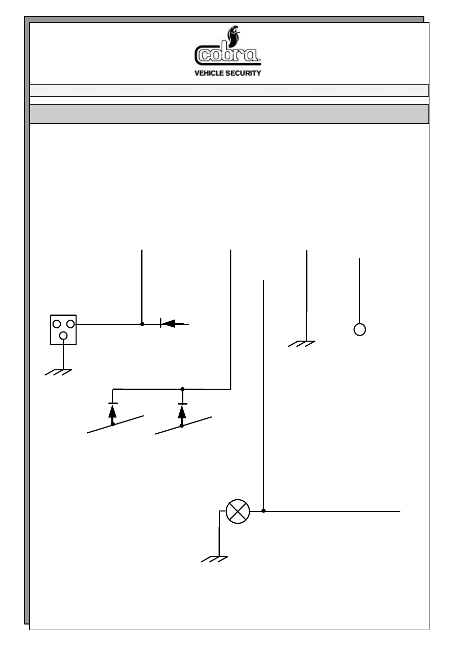
FITTING DIAGRAM NR. 187
Connection 3800 serie antitheft on
AUDI A3 year 2003
+30
ORANGE YELLOW/BLACK VIOLET/WHITE ORANGE/WHITE
VIOLET
switch inside driver’s side
door
BLUE/WHITE at position nr.13
in the 20 way connector inside
the driver’s side door
ground
1N5406 diodes
BROWN/BLUE GREY/GREEN
0,75 mm
2
0,75 mm
2
in the taped wiring harness coming out of
the motor, inside the driver’s side door
GREY/BLACK
direction indicator
BLACK/WHITE position nr.11 in
the connector marked “C” under
the driver’s side dashboard
ground
ground
1N4004 diode
Wyszukiwarka
Podobne podstrony:
A3 2003 diesel YES(1)
A4 2003 diesel YES(1)
A3 2003 diesel NO(1)
A3 1998 diesel YES
A4 2003 diesel YES
A3 1998 diesel YES
A3 2003 diesel NO
A4 2003 diesel NO(1)
A4 1998 diesel YES(1)
A4 2003 petrol YES(1)
A3 2002 petrol YES
156 2002 II sem diesel YES
A4 2003 petrol YES
A4 2003 diesel NO
A3 2002 petrol YES
A4 1998 diesel YES
A6 2003 petrol YES
Audi A3 ab 2003
więcej podobnych podstron