
1
Introduction to EMI filter Design
Presented by : Vuttipon Tarateeraseth
2
What’re EMI filters ?
EMI filter is specifically named of
“filter circuits” that used to reduce
the “EMI” generated by power
electronics equipments.
The EMI filter can’t be used to filter
out mains harmonics.

3
Why should be EMI filter ?
“EMI Filter” is an important
mitigation equipment for
suppressing undesired conducted
electromagnetic interference (EMI )
4
Where’re EMI filters ?
SMPS
5
EMI filter designers thinks in terms
of attenuation, insertion loss, voltage
drop and the number of filter sections
required to meet the insertion loss
True filter houses speak of poles,
zeros, group delay, predistortion,
attenuation and the order of the filter
Eyes of EMI filter designers
6
Basic concepts

7
Basic concepts
Insertion Loss
Lump Element Low Pass Filters
8
Insertion Loss
9
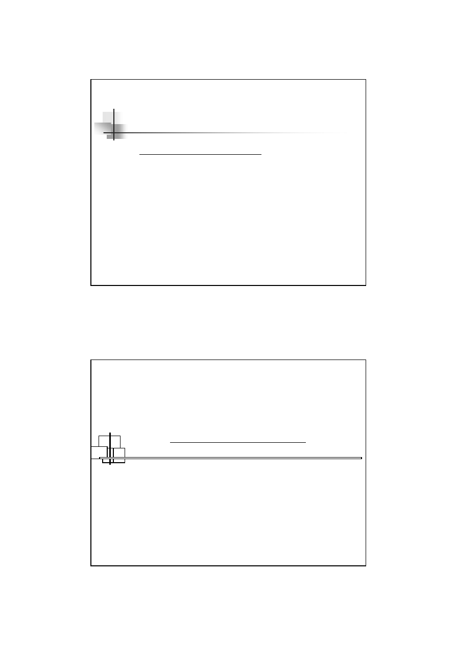
What’s Insertion Loss ?
The Insertion Loss ( IL
dB
) gives the
reduction in the load voltage
at the
frequency of interest
due to the
insertion of the filter
10
What’s Insertion Loss ?
( con’t )
=
w
L
wo
L
dB
V
V
IL
,
,
10
log
20
V
L,wo
= The output voltage of the signal source without
the filter being connected in the circuit
V
L,w
= The output voltage of the signal source at the output
terminals of the filter with the filter in the circuit
( not transfer function )
11
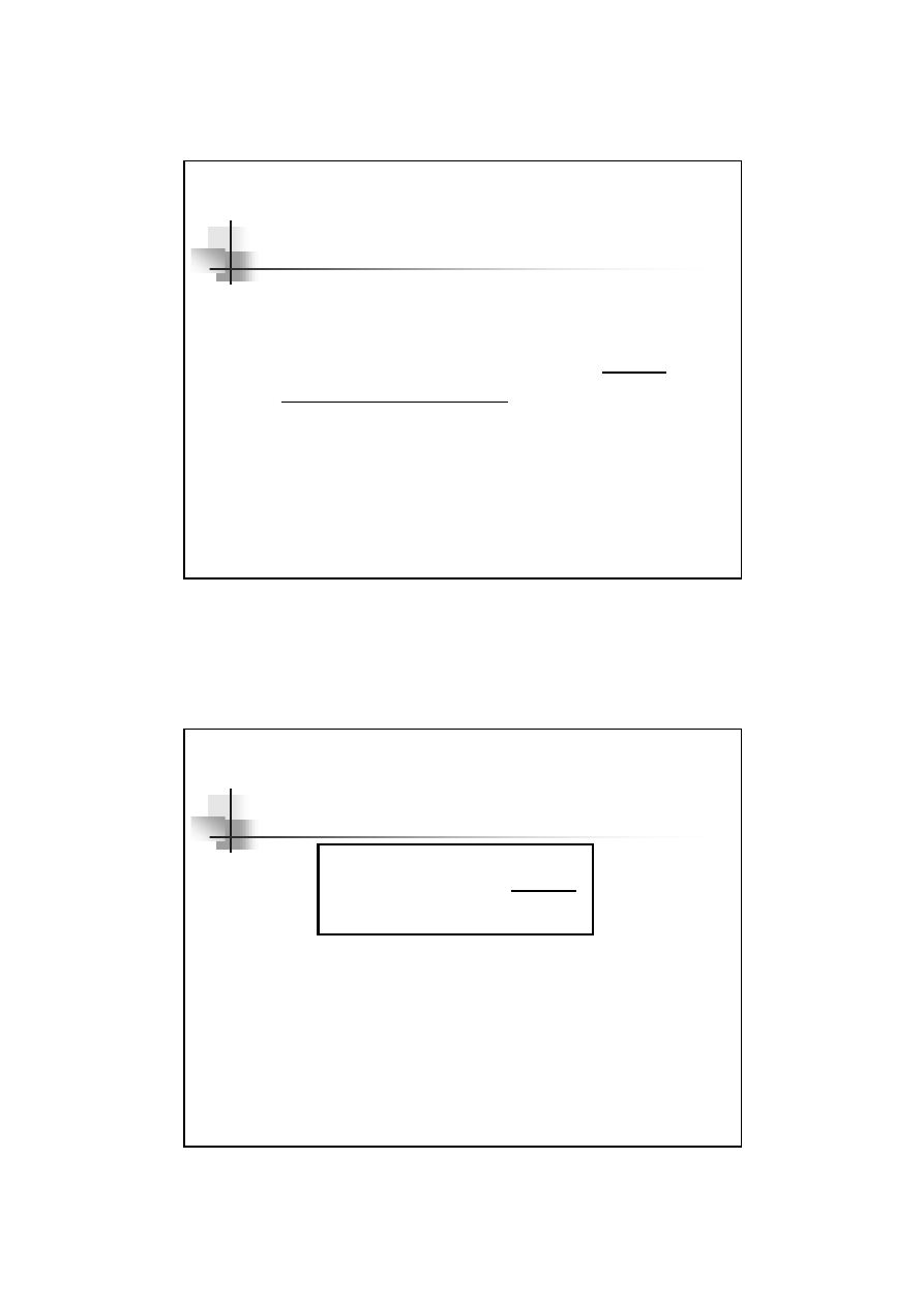
Insertion loss ( con’t )
12
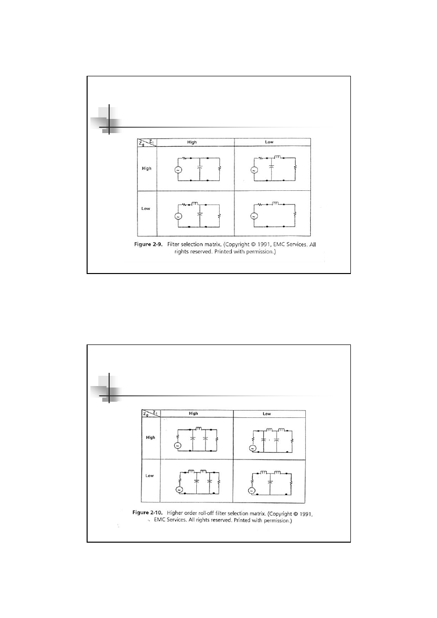
Lump element Low Pass filters
13
Lump Element Low-Pass Filters
Filtering concept
The simple capacitive filter
The simple Inductive filter
Cascade LC, T, ¶ and Why should
be cascaded ?
EMI filter
14
Filtering concepts
Filters are designed to attenuate at
certain frequencies while permitting
energy at other frequencies to pass
unchanged
The role of a filter in attenuating by
providing maximum mismatch impedance
at undesired frequencies while providing
maximum matching impedance at desired
frequencies to pass unchanged

15
Various signal filters
16
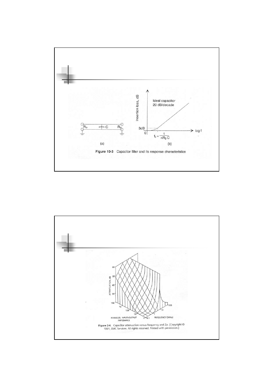
Simple capacitive filter
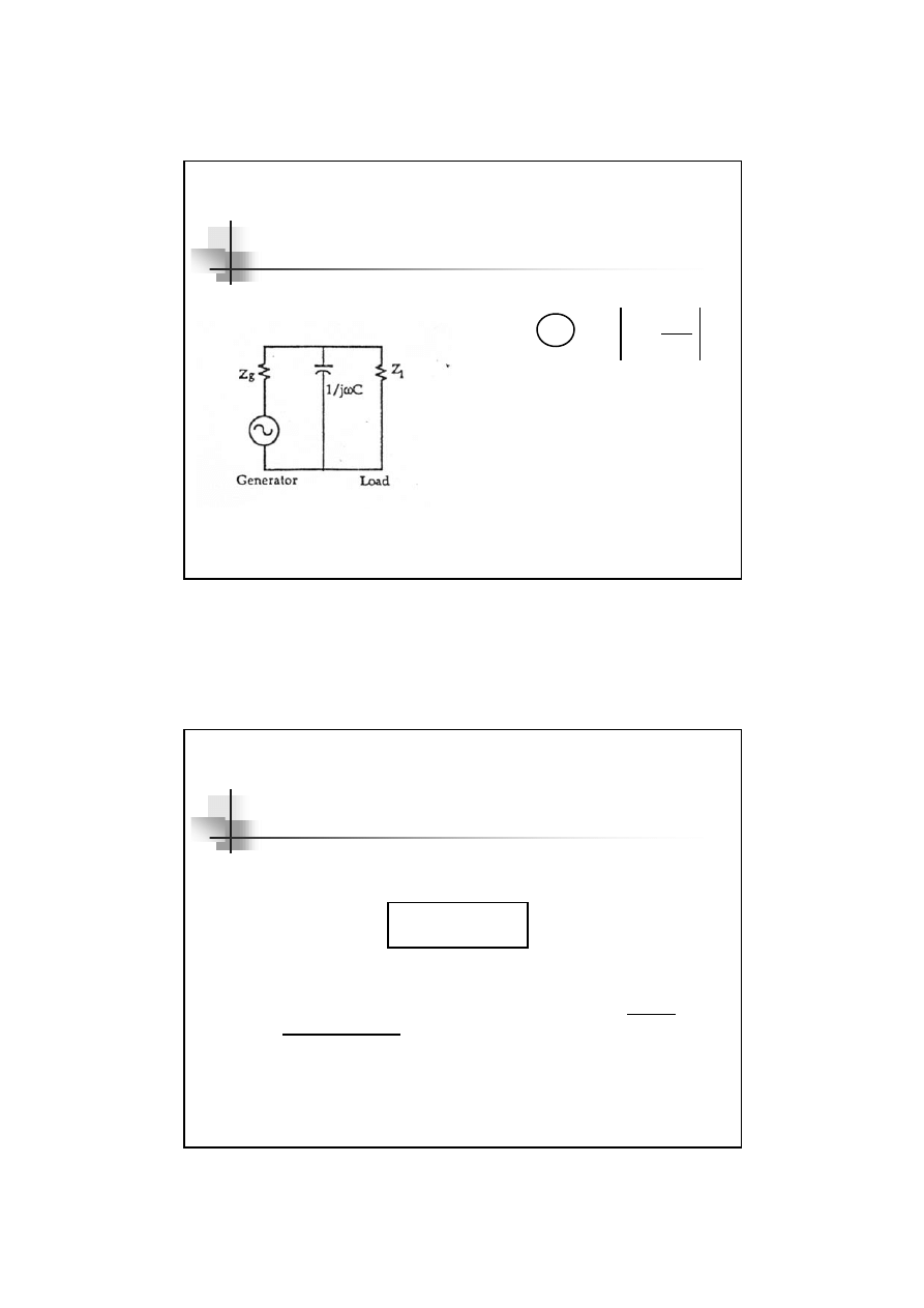
17
The simple capacitive filter
C
p
dB
Z
Z
IL
+
=
1
log
20
10
Z
p
= The Impedance of the
parallel combination of
Z
g
and Z
l
,
(Z
g
*Z
l
)/(Z
g
+Z
l
)
Z
c
= The impedance of the
filtering capacitor,
1/j
ωC
18
The simple capacitive filter ( con’t )
Capacitive is effective as a filter when
Therefore, Source and Load impedance
connected with capacitor should be high
impedance
Insertion level
= 20dB/decade
= 6 dB/octave
Z
c
<<
Z
p
19
The simple capacitive filter ( con’t )
20
The simple capacitive filter ( con’t )

21
Simple inductive filter
22
The simple inductive filter
sum
ind
dB
Z
Z
IL
+
=
1
log
20
10
Z
sum
=The Impedance of the
series combination of
Z
g
and Z
l
, ( Z
g
+Z
l
)
Z
ind
= The impedance of the
filtering inductor, j
ωL

23
The simple Inductive filter ( con’t )
Inductive is effective as a filter when
Therefore, Source and Load impedance
connected with inductor should be low
impedance
Insertion level
= 20dB/decade
= 6 dB/octave
Z
ind
>> Z
sum
24
The simple Inductive filter ( con’t )
C = parasitic capacitance
R = parasitic resistance
25
The simple Inductive filter ( con’t )
26
Cascade filter

27
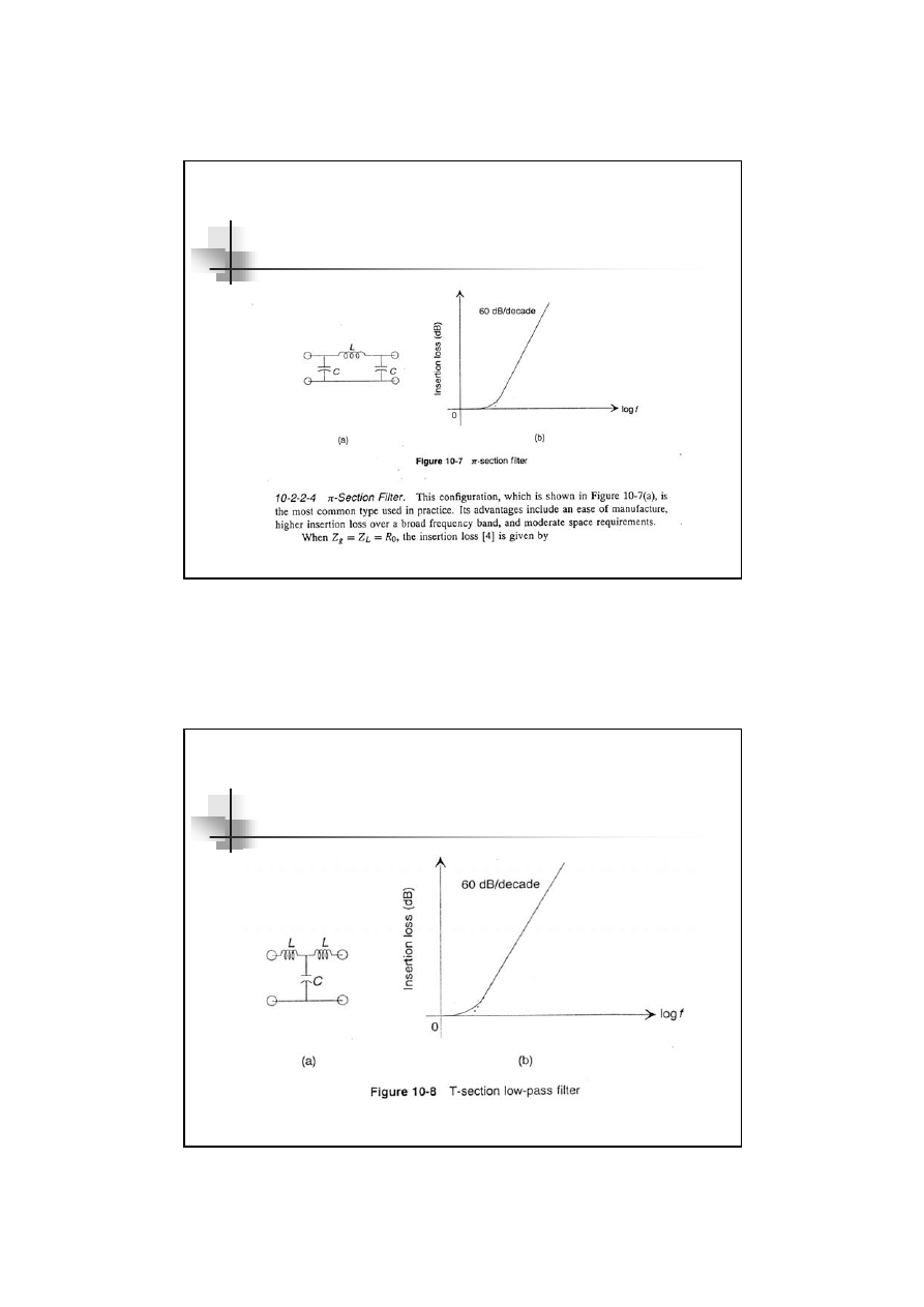
Cascade LC, T, ¶ and Why should be cascaded ?
How should you do ?
if Zin and Zout is
dissimilar ,for example : Zin = high , Zout =
low or vice versa, or when you want to
increase the Insertion Loss !!
Ans Cascade LC, T and
π
filters are mostly
useful when the source and load impedances
are very dissimilar or when you want to
increase the insertion loss!!!
28
LC filter
29
¶ - filter
30
T – filter
31
Conclusion for effective filtering
32
Conclusion for effective filtering ( con’t )
33
EMI FILTER
34
EMI filter

35
• Diagnosing conducted EMI noise mode
Two conducted noise modes :
Differential Mode (DM) and Common Mode (CM),
Dealt with separately in EMI filter design
• Methods:
⌦ Differential mode rejection network
⌦ Current probe
⌦Noise separator
Main Idea !!!
36
A basic of EMI filter diagram

37
Common mode choke
38
Effect of the filter elements on Common
and Differential mode currents

39
Separation of the conducted Emissions into
Common and Differential mode currents
40
Higher performance mains EMI filters
41
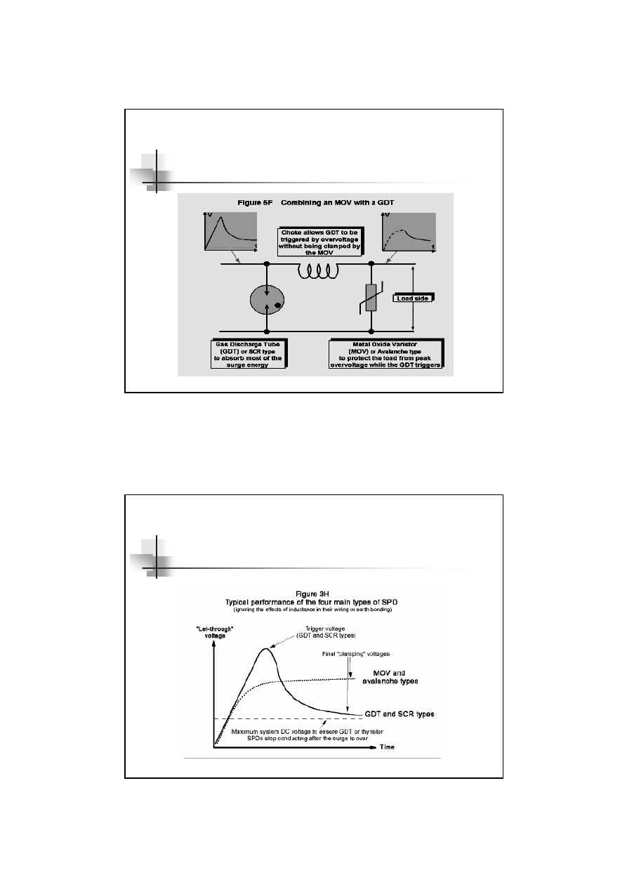
Metal Oxide Varistors ( MOVs )
42
Metal Oxide Varistors ( MOVs )
43
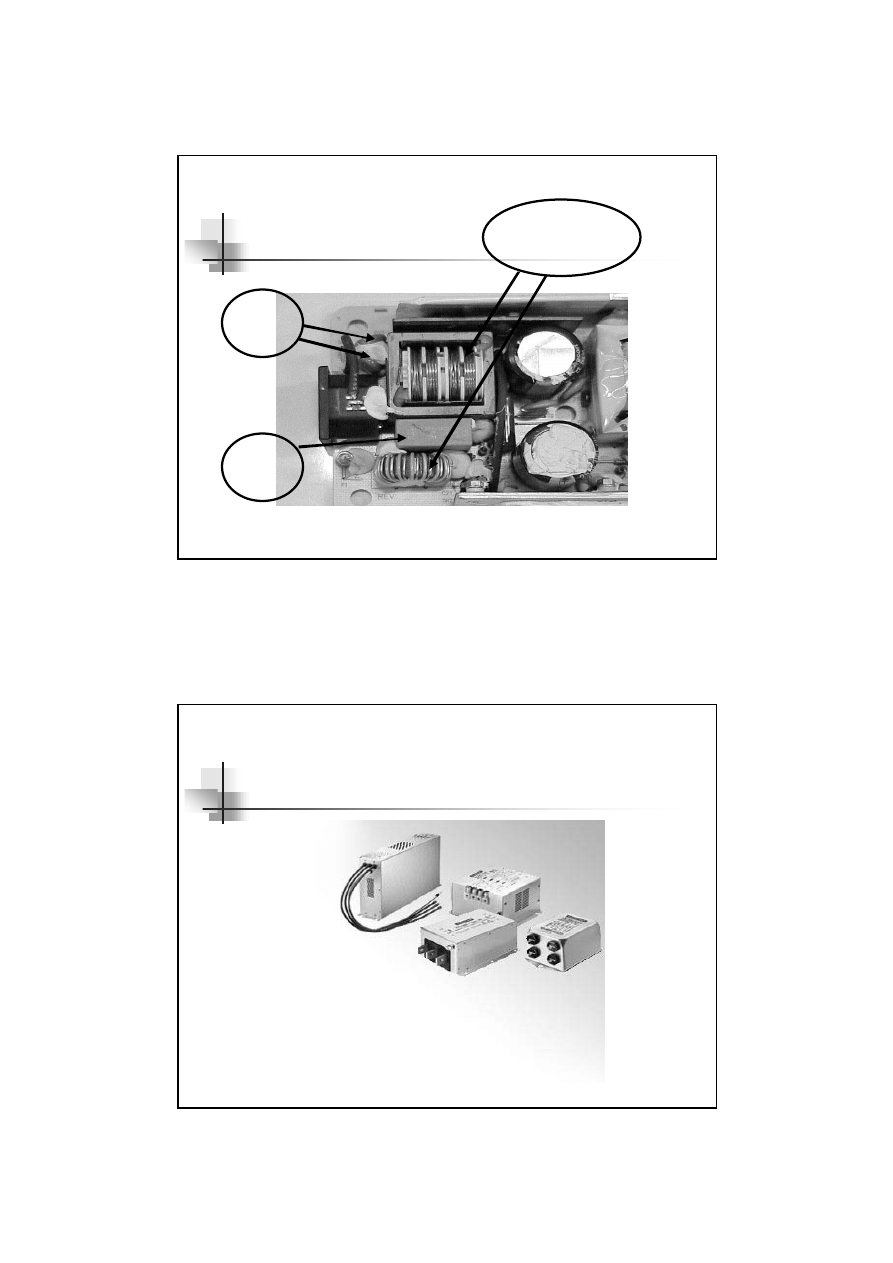
EMI filter in SMPS
C
X
Common
mode choke
C
y
44
Packaging of EMI filters
45
References
EMC for Product designers, Tim William
EMI Filter Design, Richard Lee Ozenbaugh
Engineering Electromagnetic Compatibility, V.Prasad
Kodali
Controlling conducted emissions by design, John C.
Fluke. Sr.
Power line filter design for switched-mode power
supplies, Mark J. Nave
Handbook of electromagnetic compatibility, edit by
Reinaldo Perez
Wyszukiwarka
Podobne podstrony:
Introduction to CPLD and FPGA Design
Introduction To Human Design
Non Intrinsic Differential Mode Noise of Switching Power Supplies and Its Implications to Filter Des
How to Design Programs An Introduction to Computing and Programming Matthias Felleisen
An introduction to the Kalman Filter G Welch, G Bishop
Baigent Nick An Introduction to Strategy Proof Mechanism Design
Addison Wesley An Introduction to Design Patterns
Introduction to VHDL
268257 Introduction to Computer Systems Worksheet 1 Answer sheet Unit 2
Introduction To Scholastic Ontology
Evans L C Introduction To Stochastic Differential Equations
Zizek, Slavoj Looking Awry An Introduction to Jacques Lacan through Popular Culture
Introduction to Lagrangian and Hamiltonian Mechanics BRIZARD, A J
Introduction to Lean for Poland
An Introduction to the Kabalah
Introduction to Apoptosis
Syzmanek, Introduction to Morphological Analysis
Brief Introduction to Hatha Yoga
więcej podobnych podstron