
Initial Print Date: 12/06
Table of Contents
Subject
Page
Rain Sensor . . . . . . . . . . . . . . . . . . . . . . . . . . . . . . . . . . . . . . . . . . . . . . . . . . . . . . . . . . . . . . . . . . . . . . . . . . . . . . . . . . . . . . . . . . . . . . .7
Driving Lights Sensor . . . . . . . . . . . . . . . . . . . . . . . . . . . . . . . . . . . . . . . . . . . . . . . . . . . . . . . . . . . . . . . . . . . . . . . . . . . . . . . . . . . . . . .8
Solar Sensor . . . . . . . . . . . . . . . . . . . . . . . . . . . . . . . . . . . . . . . . . . . . . . . . . . . . . . . . . . . . . . . . . . . . . . . . . . . . . . . . . . . . . . . . . . . . . . .8
RLSS Variants . . . . . . . . . . . . . . . . . . . . . . . . . . . . . . . . . . . . . . . . . . . . . . . . . . . . . . . . . . . . . . . . . . . . . . . . . . . . . . . . . . . . . . . . . . . . .9
Front Row Seating . . . . . . . . . . . . . . . . . . . . . . . . . . . . . . . . . . . . . . . . . . . . . . . . . . . . . . . . . . . . . . . . . . . . . . . . . . . . . . . . . . . . . . . .11
Second Row Seating . . . . . . . . . . . . . . . . . . . . . . . . . . . . . . . . . . . . . . . . . . . . . . . . . . . . . . . . . . . . . . . . . . . . . . . . . . . . . . . . . . . . . .11
Third Row Seating . . . . . . . . . . . . . . . . . . . . . . . . . . . . . . . . . . . . . . . . . . . . . . . . . . . . . . . . . . . . . . . . . . . . . . . . . . . . . . . . . . . . . . . .11
Rear Seat Heating without Automatic Rear-cabin Air Conditioning . . . . . . . . . . . . . . . . . . . . . . . . . . . . . . . . . . . . . . . . . . . . . .12
Rear Seat Heating with Automatic Rear-cabin Air Conditioning . . . . . . . . . . . . . . . . . . . . . . . . . . . . . . . . . . . . . . . . . . . . . . . . .13
Second Row Seat Locking . . . . . . . . . . . . . . . . . . . . . . . . . . . . . . . . . . . . . . . . . . . . . . . . . . . . . . . . . . . . . . . . . . . . . . . . . . . . . . . . .15
The Large Seat Section . . . . . . . . . . . . . . . . . . . . . . . . . . . . . . . . . . . . . . . . . . . . . . . . . . . . . . . . . . . . . . . . . . . . . . . . . . . . . . . . .15
The Small Seat Section . . . . . . . . . . . . . . . . . . . . . . . . . . . . . . . . . . . . . . . . . . . . . . . . . . . . . . . . . . . . . . . . . . . . . . . . . . . . . . . . .15
Junction-Box ECU . . . . . . . . . . . . . . . . . . . . . . . . . . . . . . . . . . . . . . . . . . . . . . . . . . . . . . . . . . . . . . . . . . . . . . . . . . . . . . . . . . . . . .17
E70 General Vehicle Electronics Workbook
Revision Date:

Table of Contents
Subject
Page
Park Distance Control . . . . . . . . . . . . . . . . . . . . . . . . . . . . . . . . . . . . . . . . . . . . . . . . . . . . . . . . . . . . . . . . . . . . . . . . . . . . . . . . . . . . . .22
Rear View Camera . . . . . . . . . . . . . . . . . . . . . . . . . . . . . . . . . . . . . . . . . . . . . . . . . . . . . . . . . . . . . . . . . . . . . . . . . . . . . . . . . . . . . . . . .22
Basic Functions of the Rear-view Camera System . . . . . . . . . . . . . . . . . . . . . . . . . . . . . . . . . . . . . . . . . . . . . . . . . . . . . . . . . . . . .24
Image Reproduction Functions . . . . . . . . . . . . . . . . . . . . . . . . . . . . . . . . . . . . . . . . . . . . . . . . . . . . . . . . . . . . . . . . . . . . . . . . . . . . .24
Lens Coverage Alignment . . . . . . . . . . . . . . . . . . . . . . . . . . . . . . . . . . . . . . . . . . . . . . . . . . . . . . . . . . . . . . . . . . . . . . . . . . . . . . . . . .25
Electronic Image Equalization . . . . . . . . . . . . . . . . . . . . . . . . . . . . . . . . . . . . . . . . . . . . . . . . . . . . . . . . . . . . . . . . . . . . . . . . . . . . . . .25
View of Image Section . . . . . . . . . . . . . . . . . . . . . . . . . . . . . . . . . . . . . . . . . . . . . . . . . . . . . . . . . . . . . . . . . . . . . . . . . . . . . . . . . . . . .25
Virtual Camera Pan . . . . . . . . . . . . . . . . . . . . . . . . . . . . . . . . . . . . . . . . . . . . . . . . . . . . . . . . . . . . . . . . . . . . . . . . . . . . . . . . . . . . . . . .25
Camera Pan as a Function of Speed . . . . . . . . . . . . . . . . . . . . . . . . . . . . . . . . . . . . . . . . . . . . . . . . . . . . . . . . . . . . . . . . . . . . . . . .26
Additional Functions of the Rear-view Camera System . . . . . . . . . . . . . . . . . . . . . . . . . . . . . . . . . . . . . . . . . . . . . . . . . . . . . . . .26
Assistance Graphics in Camera Image . . . . . . . . . . . . . . . . . . . . . . . . . . . . . . . . . . . . . . . . . . . . . . . . . . . . . . . . . . . . . . . . . . . .26
Lane Help Lines . . . . . . . . . . . . . . . . . . . . . . . . . . . . . . . . . . . . . . . . . . . . . . . . . . . . . . . . . . . . . . . . . . . . . . . . . . . . . . . . . . . . . . . .27
Turning Circle Lines . . . . . . . . . . . . . . . . . . . . . . . . . . . . . . . . . . . . . . . . . . . . . . . . . . . . . . . . . . . . . . . . . . . . . . . . . . . . . . . . . . . . .27
Obstacle Markings . . . . . . . . . . . . . . . . . . . . . . . . . . . . . . . . . . . . . . . . . . . . . . . . . . . . . . . . . . . . . . . . . . . . . . . . . . . . . . . . . . . . . .27

Table of Contents
Subject
Page
Rear-View Camera Design . . . . . . . . . . . . . . . . . . . . . . . . . . . . . . . . . . . . . . . . . . . . . . . . . . . . . . . . . . . . . . . . . . . . . . . . . . . . . . . . . .29
Location of Rear-view Camera . . . . . . . . . . . . . . . . . . . . . . . . . . . . . . . . . . . . . . . . . . . . . . . . . . . . . . . . . . . . . . . . . . . . . . . . . . . . . .30

4
E70 General Vehicle Electronics Workbook
General Vehicle Electronics
Model: E70
Production: From Start of Production
After completion of this module you will be able to:
• Identify the components and sub-systems that make up the vehicle electrical system
• Identify the different 2
nd
row seat heating options available
• Properly diagnose the 2
nd
row seat recognition microswitches
• Perform a rear view camera adjustment
E70 General Vehicle Electronics Workbook
5
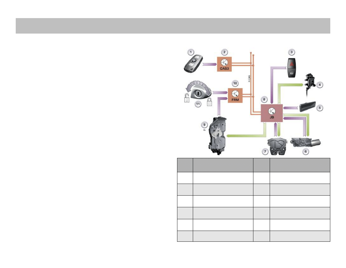
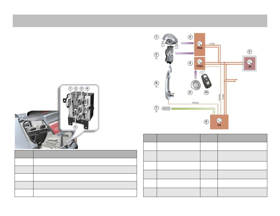
The central locking is the central vehicle access system. It is
responsible for unlocking and locking the vehicle. The central
locking controls all vehicle doors, the upper section of the two-
piece tailgate and the fuel filler flap.
The central locking can be operated via the following compo-
nents:
• Remote control
• Driver's door lock barrel (door lock)
• Center lock button
• Exterior tailgate button
• Identification transmitter and outer door handle electronic
module TAGE for Comfort Access.
A correspondingly adapted electrical system taken from the E90 is
used in the E70. For this reason, many components and functions
stem from the E90.
The Car Access System now features the third generation of con-
trol units. The electronic vehicle immobilizer 4 is also used in con-
nection with the Car Access System 3. The Car Access System 3
is backwards compatible with the Car Access System 2.
Therefore, the Car Access System 3 contains all the functions of
its predecessor.
It is possible to open and close the vehicle both actively or pas-
sively. Option SA 322 Comfort Access is required for the passive
opening and closing function.
Note: The lower section of the tailgate is fully mechanical
and can be opened as soon as the upper section has
been opened.
System Overview
Index
Explanation
Index
Explanation
1
Remote control
7
Central locking, tailgate
2
Car Access System 3 CAS 3
8
Junction box control unit JB
3
Center-lock button
9
Lock (4x) in vehicle doors
4
Central locking, fuel filler flap
10
Footwell module FRM
5
Exterior tailgate button
11
Driver's door lock barrel
6
Automatic soft-close drive unit,
tailgate
K-CAN
Bodyshell CAN
Central Locking
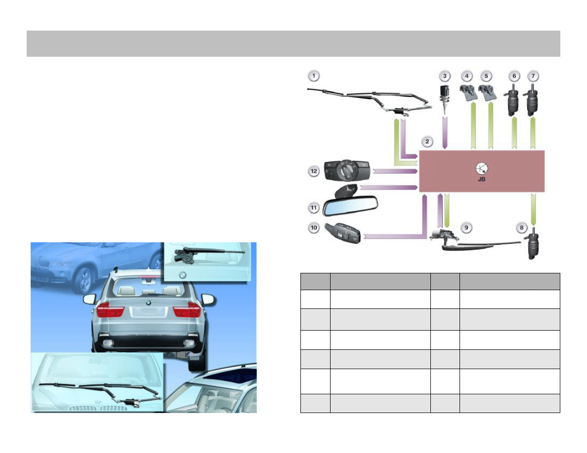
The E70 is equipped with two Windshield wipers and one rear
window wiper as standard.
The wiper function is possible in the following modes:
• Intermittent wipe
• Continuous wipe in Stage 1
• Continuous wipe in Stage 2
• Flick wipe
The E70 can be optionally equipped with headlight washer sys-
tem option 502. It is equipped with rain/driving lights/solar sensor
and heated nozzles as standard.
The wipe/wash system on the E70 is a conventional wipe/wash
system. This means that the wiper motors are equipped with a
reset contact.
6
E70 General Vehicle Electronics Workbook
Index
Explanation
Index
Explanation
1
Front wiper motor
7
Motor, headlight washer
2
Junction box control unit JB
8
Motor for washer fluid pump,
rear
3
Outside temperature
9
Wiper motor, rear
4
Heated water jet, driver's side
10
Steering column switch, wipers
5
Heated water jet,
front passenger's side
11
Rain/driving lights/solar sensor
6
Motor, washer fluid pump, front
12
Lights operating unit
Wipers
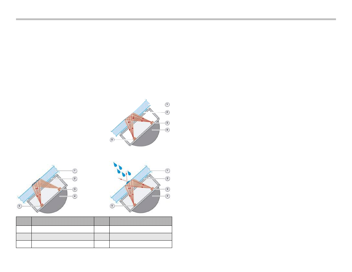
Rain Sensor
With the aid of three infrared transmit diodes and infrared receive
diodes, the rain sensor evaluates the moisture level on the
Windshield.
Three rain ranges are created by combining infrared transmit
diodes and infrared receive diodes in pairs. The rain ranges are
used to determine the rain intensity.
Rain detection is based on the reflection of the infrared light at
the boundary surface from the glass of the Windshield to air.
The reflection is dependent on the level of soiling and moisture
on the Windshield.
The infrared light is reflected in full when
the Windshield is clean and dry.
The reflection of the infrared light is reduced by dirt or rain water on
the Windshield.
The rain sensor signals the detected rain situation to the roof
functions center via the LIN-bus. In turn, the roof functions center
transfers the information on the K-CAN. In this way, the junction
box control unit receives the request to switch the windshield
wiper on or off.
The signals are:
• Sensor status
• Rain intensity
• Wiper speed
• Interval period
E70 General Vehicle Electronics Workbook
7
Index
Explanation
Index
Explanation
1
Windscreen
4
Rain/driving lights/solar sensor
2
Adhesive layer
5
Infrared transmit diode
3
Infrared receive diode
Driving Lights Sensor
The driving lights sensor registers the ambient light and the light
levels in front of the vehicle (front end). A sensor for each of these
areas is integrated in the rain/driving lights/solar sensor.
The rain/driving lights/solar sensor informs the roof functions center
of the driving lights situation via the LIN-bus, i.e. driving lights on/off
and reason for switching on.
The roof functions center packs the signals into the corresponding
K-CAN telegram and sends it. In this way, the footwell module
receives the request to switch the driving lights on or off (when the
automatic driving lights function is active).
The signals are:
• Status of driving lights sensor
• Status of driving lights
• Ambient brightness level
• Reason for switching on.
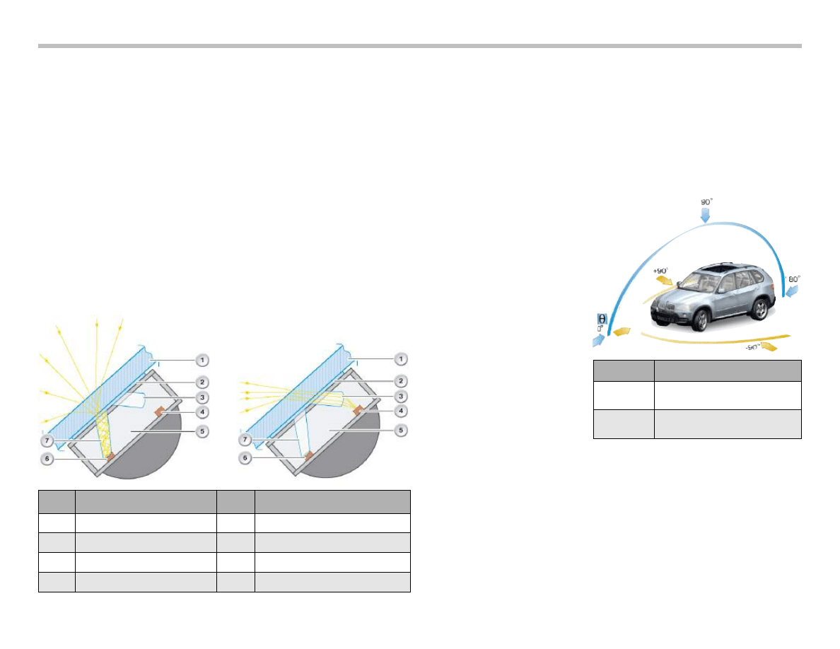
Solar Sensor
The solar sensor is assigned purely to the scope of functions of the
automatic heating and air conditioning system.
The solar sensor measures the angle of solar radiation (insolation)
on to the vehicle. The solar radiation is measured separately on the
driver's and front passenger's side.
At times the solar radiation comes from the front, from the side or
sometimes from the rear due to the changes
in direction while driving. The sensor
therefore registers the solar radiation at
all times.
Persons in the vehicle are sub-
jected to these changing lev-
els of solar radiation (insola-
tion). Consequently, more
heat is felt in the area of
solar radiation than in the
area with no solar radiation.
The solar sensor measures
the solar radiation on to the
vehicle depending on the
position of the car with
respect to the sun.
The values from the solar enable the integrated automatic heating
and air conditioning system (climate control) to respond according-
ly and create a pleasant climate in the vehicle. The roof functions
center receives the values from the solar sensor via the LIN-bus
and forwards the values on the K-CAN to the integrated automatic
heating and air conditioning system (climate control).
8
E70 General Vehicle Electronics Workbook
Index
Explanation
Index
Explanation
1
Windscreen
5
Rain/driving lights/solar sensor
2
Adhesive layer
6
Infrared transmit diode
3
Light optics, front end sensor
7
Receive diode, ambient light sensor
4
Receive diode, front end sensor
Index
Explanation
q
(Theta)
Angle of incidence of
solar radiation
j
(Phi)
Course of the sun from
sunrise to sunset

RLSS Variants
Two versions of the rain/driving lights/solar sensor are used in
the E70. The version depends on whether a head-up display is
installed in the vehicle or not. The optics in the front end light
sensor that are pervious to infrared light are replaced by clear
optics for the head-up display.
The front end light sensor is directed at the area of the road which
is also used for the head-up display. The brightness level of the
representation in the head-up display can thus be adapted to the
light situation.
This is necessary for example when driving through a tunnel with
the head-up display switched on.
Installation of the rain/driving lights/solar sensor in the E70 requires
the installation of the roof functions center with maximum equip-
ment configuration. Consequently, the maximum equipment con-
figuration of the interior lighting system is also installed.
Note: The rain/driving lights/solar sensor can best be
distinguished simply by looking at the Windshield.
If the rain/driving lights/solar sensor has two clear
lenses then it is for the head-up display.
The optical element and the electronics of the rain/driving
lights/solar sensor can be replaced separately.
Note: An exception is the rain/driving lights/solar sensor
for the head-up display. This rain/driving lights/solar
sensor can be replaced only as a complete unit. The
reason for this is that the optical element and the
electronics need to be matched (calibrated) in the
sensor for the head-up display. This is currently
possible only as part of the rain/driving lights/solar
sensor manufacturing process.
The occurrence of small bubbles on the silicon gel layer (adhesive
layer) is OK (permitted) when replacing the optical element. Please
remember to initialize the rain/driving lights/solar sensor.
E70 General Vehicle Electronics Workbook
9
Using Comfort Access the customer can unlock and open the
vehicle without active use of the ID transmitter. It is unimportant
how the customer wishes to access the vehicle. It is important that
the ID transmitter be located in the vehicle's immediate vicinity
(approximately 2m). It is sufficient to have the ID transmitter some-
where on your person.
The system is based on the Comfort Access on the E90/E91.
Inserting a hand into the handle recess of the outside door handle
unlocks and then opens the vehicle. The vehicle is locked by
touching the sensitive area of the outside door handle.
10
E70 General Vehicle Electronics Workbook
Index
Explanation
Index
Explanation
1
Driver's door lock cylinder
7
Interior antenna x 5
2
Lock with door contact x 4
8
Outside door handle
electronics module
3
Footwell module FRM
9
START-STOP button
4
Car Access System 3 CAS 3
10
ID transmitter
5
Junction box control unit JB
K-CAN
Body CAN
6
Comfort access CA
CAS-Bus
CAS-bus (K-bus protocol)
Index
Explanation
1
Comfort Access
2
Trailer module
3
Park Distance Control
4
Vertical Dynamic Management
5
Electronic ride-height control
Comfort Access
E70 General Vehicle Electronics Workbook
11
Front Row Seating
There are two different seats available:
• Sport seat
• Multifunction seat (comfort seat) option
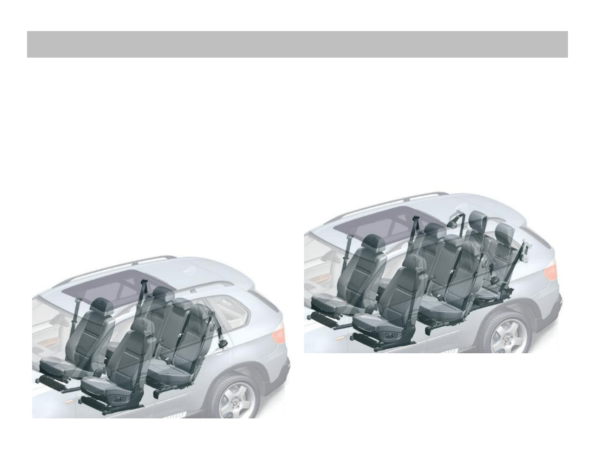
Second Row Seating
The E70 is a five-seater in its standard equipment specification,
two seats in the front (driver and Passenger) and three seats in the
row just behind the front seats. This is referred to as second row
seating (back seat). It offers the opportunity of folding down the
backrest completely, thereby increasing the luggage-compartment
volume.The backrest are divided into two parts, the ratio being
60/40.
Third Row Seating
The Passenger seating capacity can be extended to seven by
ordering the third row seating option.The additional two seats are
situated in the luggage compartment and can be folded down
completely.
This row of seats is referred to as third row seating or 5 + 2 seat
concept and are not equipped with seat heaters. However, an
independent heating unit option is available just for the third row
seats.
Third Row Seats
Front and Second Row Seating
Seats
The Seat heating option is also available for second row seats.
Seat heating is an option The seat heating option cannot be
ordered individually. This means that it can only be ordered in
conjunction with the Front Seat-heating option.
Seat heating for the second row is available in two equipment
specifications:
• Without automatic rear-cabin air conditioning
• With automatic rear-cabin air conditioning
Rear Seat Heating without Automatic Rear-cabin
Air Conditioning
The seat heating features two heating circuits each in the right and
left seat halves. Each of the heating circuits has a heating area for
the backrest and the seat cushion.
The seat heating is connected to the "Terminal 15" relay. The seat
heating can therefore only be activated from "Terminal 15 ON".
The seat heating can be switched on individually for the left or right
seat half with buttons.
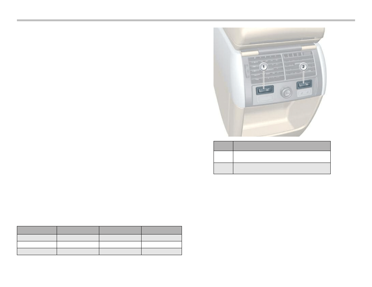
The seat-heating buttons are integrated under the air vents in the
rear center console.
The seat heating can be switched on in two heating stages. The
heating stages and their indications are set out in the following
table.The seat heating is controlled by means of an NTC resistor
in the heating mat of the seat surface. The buttons are
resistance-coded and make a different supply voltage available for
the seat heating.
12
E70 General Vehicle Electronics Workbook
Index
Explanation
1
Seat-heating button, driver's side, rear
2
Seat-heating button, front
passenger side, rear
Heating stage
Seat
Backrest
LED
2
Normal
Normal
2
1
Low
Low
1
0
OFF
OFF
OFF
Note: The Car Access System 3 actuates a relay in the front
distribution box. The front distribution box is thus
supplied with "Terminal 15 ON" (7). The Terminal 15
relay (5) among others is connected to this supply.
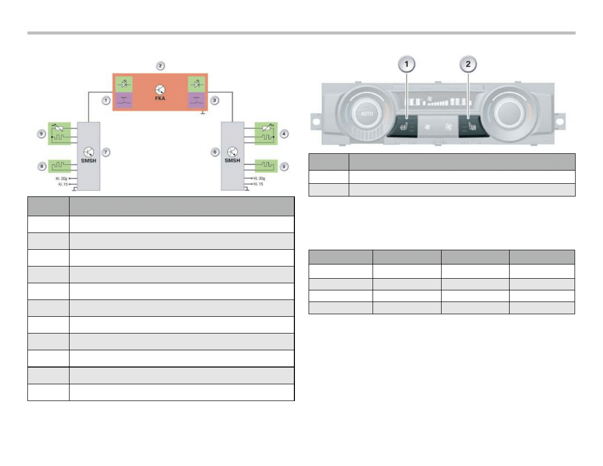
Rear Seat Heating with Automatic Rear-cabin
Air Conditioning
The seat heating has two heating circuits, as described above.
It does, however, have a seat-heating seat module.
The function of the seat heating is integrated completely in the
seat-heating seat module. The seat-heating seat module is con-
nected to terminal 30 for the load current.
The seat heating can be activated from the status "Terminal 15
ON". Automatic rear cabin air conditioning receives the status
"Terminal 15 ON" via the K-CAN.
The buttons for operating the seat heating are integrated in the
control panel for automatic rear-cabin air conditioning. The auto-
matic rear-cabin air conditioning ECU evaluates the buttons and
activates the seat heating depending on the selected heating
stage.
The seat-heating seat module is supplied with a pulse-width-mod-
ulated signal for this purpose. The pulse width corresponds to the
required heating stage.
The seat-heating seat module executes the request and monitors
the seat heating. The seat-heating seat module determines the set
temperature by means of an NTC resistor in the heating mat of the
seat surface.
E70 General Vehicle Electronics Workbook
13
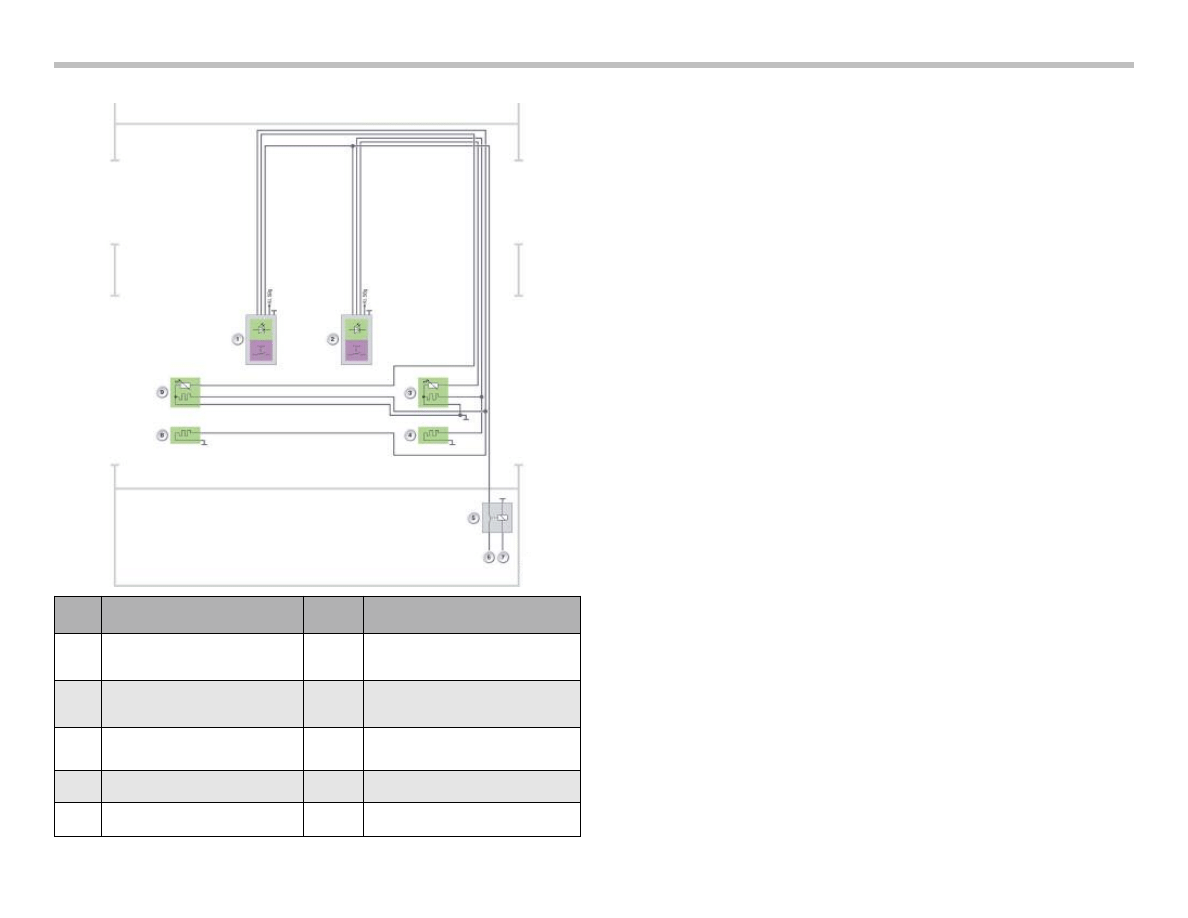
Rear Seat Heating without FKA Circuit Diagram
Index
Explanation
Index
Explanation
1
Seat-heating button, driver side,
with function indicator
6
Terminal 30 (distribution box, front)
2
Seat-heating button,
front passenger side,
with function indicator
7
Terminal 15 ON
(switched by CAS3)
3
Seat heating, seat surface,
front passenger side
8
Seat heating, backrest, driver side
4
Seat heating, backrest,
front passenger side
9
Seat heating, seat surface,
driver side
5
Relay, terminal 15
KL 58g
Terminal 58 switched
The seat heating can be switched on in three heating stages.
The heating stages and their indications are set out in the following
table.
14
E70 General Vehicle Electronics Workbook
Rear Seat Heating with FKA Circuit Diagram
Seat Heating Buttons with FKA
Heating stage
Seat
Backrest
LED
3
High
High
3
2
Normal
Normal
2
1
Low
Low
1
0
OFF
OFF
OFF
Index
Explanation
1
Seat-heating button, driver side, with function indicator, rear
2
Automatic rear-cabin air conditioning
3
Seat-heating button, front passenger side, with function indicator, rear
4
Seat heating, seat surface, front passenger side
5
Seat heating, backrest, front passenger side
6
Seat-heating seat module, front passenger side, rear
7
Seat-heating seat module, driver side, rear
8
Seat heating, backrest, driver side
9
Seat heating, seat surface, driver side
KL 30g
Terminal 30 switched
KL 15
Terminal 15 (distribution box, front)
Index
Explanation
1
Seat-heating button, driver side
2
Seat-heating button, front passenger side
Second Row Seat Locking
The locking function of the seat bench in the second seat row is
monitored. For example, a locked seat bench ensures that it cannot
come loose during driving and result in passenger injuries.
The second row seats are divided into a large and a small seat
sections. The ratio is 60-40. Therefore, the large seat portion has
four Micro-witches while the small seat portion has one Micro-
switch for monitoring the lock.
The junction-box ECU issues a signal as soon as the contact to the
ground connection is interrupted. The signal alerts the customer
that the second row is not locked correctly.
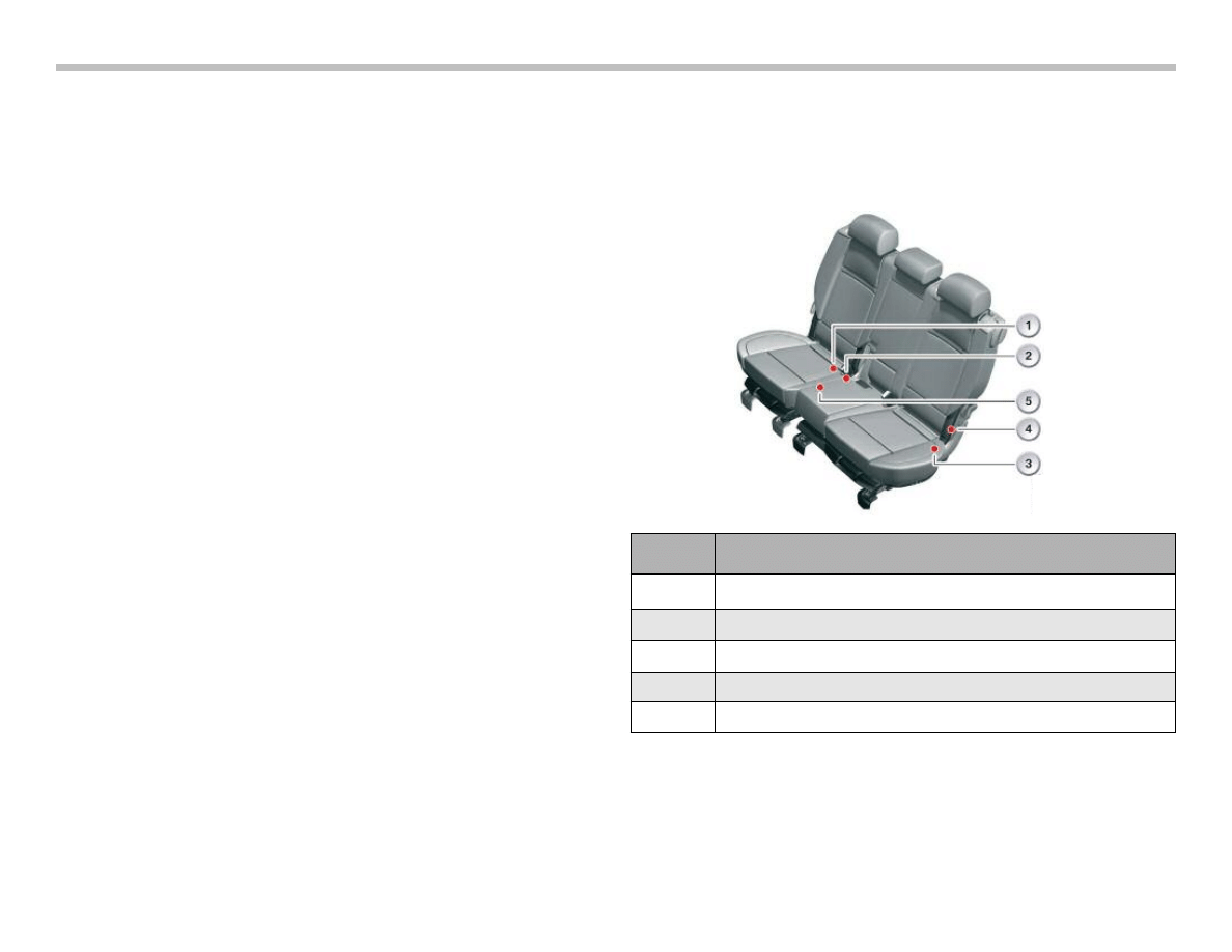
The Large Seat Section
Micro-witches are installed for the backrest and seat surface for
monitoring the large seat section. On the backrest there is only one
Micro-switch, on the outside.
There are two further Micro-witches in the seat bottom, on the
inside and outside of the locks. Another Micro-switch is located on
the seat-cushion arm in the seat bottom to detect when the back-
rest is in the fully set-down in position and locked.
All the switches are closed when the seat section is correctly
locked. One of the switches of a locked seat is always open or
closed. The following seat states are monitored:
• Large seat half, backrest, folded up and locked
• Large seat half, backrest, folded down
• Large seat half, seat surface tilted
• Large seat half, seat surface locked
The Small Seat Section
The small seat section is monitored by a Micro-switch, since there
is no belt integrated in the backrest. The Micro-switch is situated
on the mechanical lock on the inside of the seat bottom. The
switch is closed when this seat is correctly locked.
E70 General Vehicle Electronics Workbook
15
Index
Explanation
1
Micro-switch, seat (40 % seat, lock on seat bottom)
2
Micro-switch, large seat half (60% lock, seat, inner)
3
Micro-switch, large seat half (60% lock, outer)
4
Micro-switch, large seat half (60% backrest, outer)
5
Micro-switch, large seat half (60% seat-cushion arm, inner)
16
E70 General Vehicle Electronics Workbook
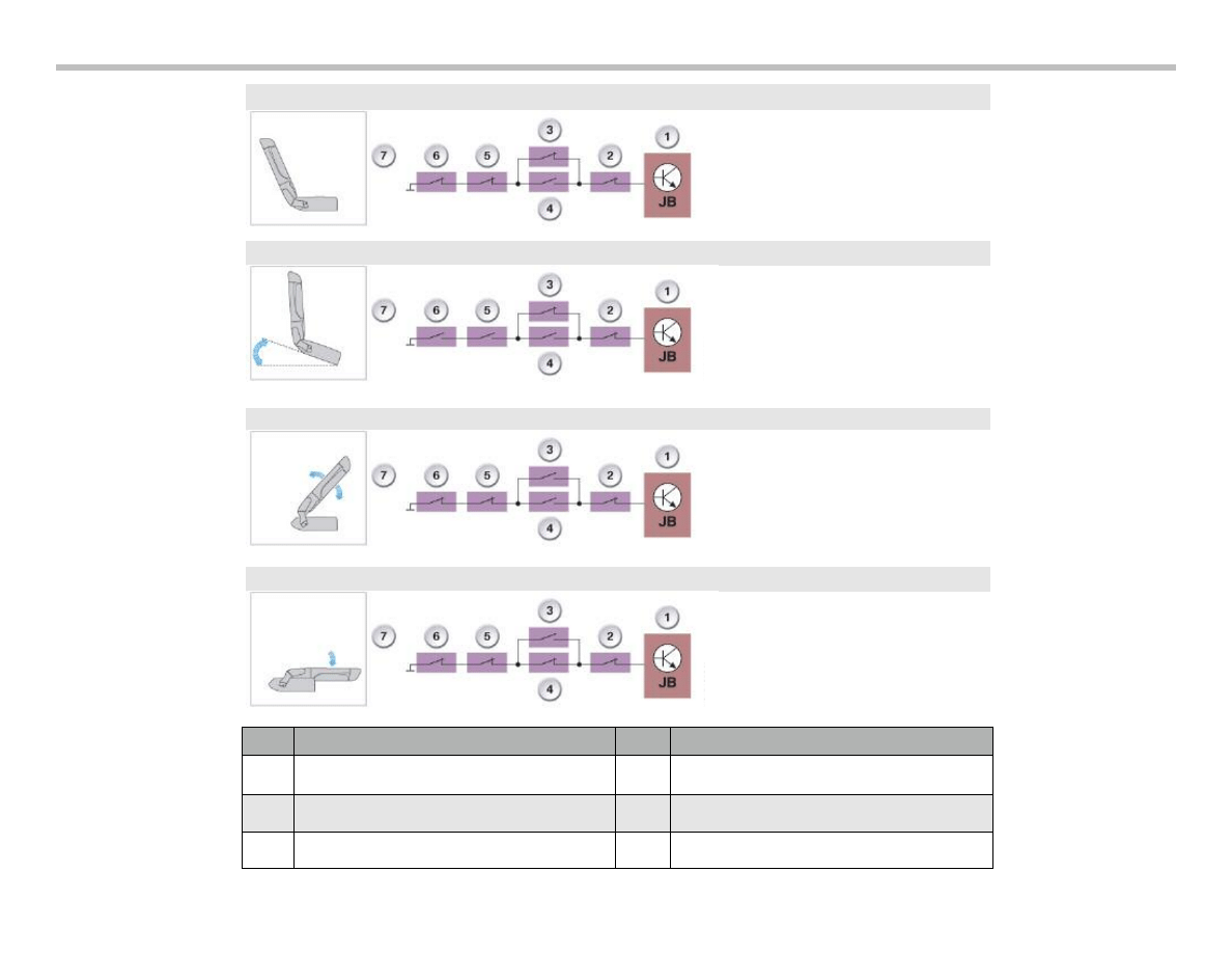
Seat position, second seat
row completely locked
Large seat half, seat bench
tilted (also called Easy
Entry)
Large seat half, backrest,
folded down, not locked
Large seat half, backrest,
folded down
Index
Explanation
Index
Explanation
1
Junction-box ECU (JB)
5
Micro-switch, large seat half (backrest, outer)
2
Micro-switch, small seat half (40%)
6
Micro-switch, large seat half (seat cushion arm)
3 & 4
Micro-switches, large seat half (seat, inner/outer)
7
Seat position/backrest position

E70 General Vehicle Electronics Workbook
17
Junction-Box ECU
The junction-box ECU is the monitoring electronic control unit. In
the event of an incorrectly locked seat, the junction-box ECU no
longer has ground contact with this pin.
The signal level therefore changes from Low to High. The junction-
box ECU issues a check control message and alerts the driver to
an unlocked seat.
Third Row Seat
The seat concept described above can be extended by the 5+2
seat concept. This is available as the 5+2 seat-extension option.
The additional two seats are situated in the luggage compartment
and can be folded down completely. This seat row is the third row
in the E70.
These seats are not equipped with seat heating. However, an
independent heating option is available for the third row. More
information can be found in the Product Information "E70
Heating / Air Conditioning".
Seat-position Recognition, US Version
The US version of the driver seat has seat position recognition.
Seat-position recognition indicates where longitudinally the seat is
situated (distance to the steering wheel). In this way, the distance
between the driver and the steering wheel can be detected.
The ACSM requires this information so that it can fire the airbag
under defined conditions. A more detailed description can be
found in the Product Information "E70 Advanced Crash Safety
Management".
Seat-position recognition is calibrated at the factory. The positions
in the front and rear longitudinal seat direction are known to the
seat module. A maximum distance is available for longitudinal seat
adjustment.
This stretches from the mechanical front stop to the mechanical
rear stop. The motor for adjustment in the longitudinal direction
generates Hall pulses over this distance. The seat modules uses
these Hall pulses to identify the current (absolute) seat position.
An area for example in which a person of short stature would sit is
defined in the longitudinal direction. The absolute seat position can
be lost due to specific causes. The seat must therefore be calibrat-
ed. Please refer to the Service Information.

18
E70 General Vehicle Electronics Workbook
1) Locate and display the Second Row Seat Locking Detection
system schematic.
Draw the Micro-switch schematic in the box below.
2) How many switches are used in the system?
Circle the best possible answer.
3) What type of circuit are the Micro-switches wired in?
Circle the best possible answer.
4) Unlock and operate the seat (Easy entry function) and note
what happens
5) Unlock the large seat backrest, pull forward and note what
happens.
6) Which air bag triggering logic is affected directly by this monitor-
ing system?
Circle the best possible answer.
Workshop Exercise - Second Row Seat Locking Detection
Using an instructor assigned E70 vehicle, the Seat Position Micro-switches poster and diagnostic equipment, answer the follow-
ing questions.
Two
Four
Five
Parallel
Series
Series Parallel
Driver and Passenger
Side Air Bags
None
Curtain Air Bags
E70 General Vehicle Electronics Workbook
19
A steering column switch cluster SZL is used on the E70 that can
detect the steering angle and the settings of the steering column
switches for wiper, direction indicator light and cruise control by
means of optical sensors.
In addition to the optical sensors, buttons based on switching-mat
technology are used for the buttons on the multifunction steering
wheel and various buttons on the steering column stalks. The
voltage signals are read by the steering column switch cluster.
The information from the switches and steering angle sensor are
in part processed in the steering column switch cluster and trans-
ferred to other systems via the F-CAN. A part of the information is
forwarded directly to other control units.
Note: In terms of design and function, the steering
column switch cluster essentially corresponds
to the steering column switch cluster on the E90.
A new feature is the electronic steering wheel
module that is responsible for controlling the
steering wheel heating.
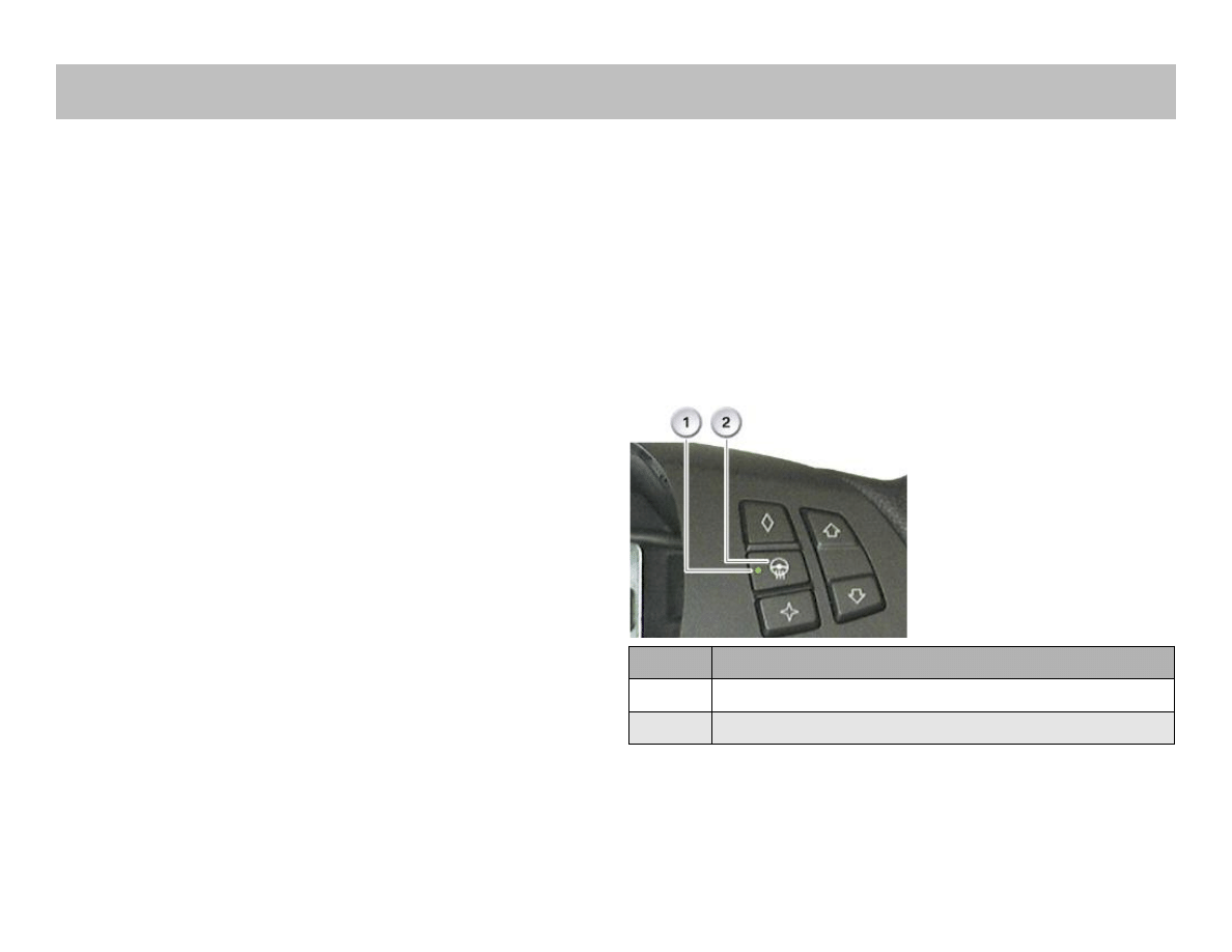
Steering Wheel Heating
The steering wheel heating is controlled by the electronic steering
wheel module. The electronic steering wheel module is accom-
modated in the steering wheel.
The steering wheel heating is activated by means of a switch on
the steering wheel. The switch is connected directly to the elec-
tronic steering wheel module. The power is supplied via two dedi-
cated connections.
To prevent overloading the electrical system, the function can be
deactivated by the IHKA by means of a power-down connection.
Index
Explanation
1
Steering Wheel Heating Indicator Light
2
Steering Wheel Heating Button
Steering Column Switch Electronics
20
E70 General Vehicle Electronics Workbook
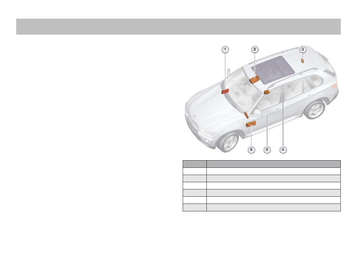
The interior lighting in the E70 is based on the interior lighting
system implemented in the E90. The interior lighting comprises
the roof area, luggage compartment, footwell and inner door
lighting.
The lighting in outer area of the doors is provided by the
courtesy lighting (outer door handles) and the exit lights. The inte-
rior lighting in the roof area on the rear driver and passenger sides
consists of two separate lamps. A new feature is the split glove
compartment.
The complete glove compartment lighting is powered and
controlled by an electronic module in the unlocking/release
drive unit.
The following diagram shows where the control units responsible
for the interior lighting are located in the E70.
Index
Explanation
1
Junction box control unit
2
Advanced crash safety management
3
Roof function center
4
Car access system 3
5
Comfort Access
6
Footwell module
Interior Lighting
E70 General Vehicle Electronics Workbook
21
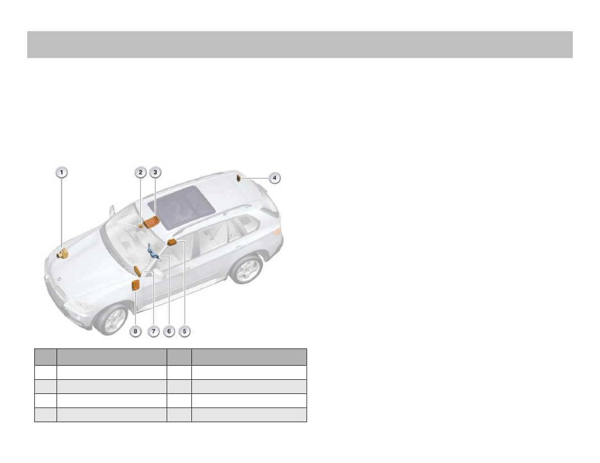
The exterior lighting in the E70 is based on the exterior lighting
system implemented in the E90. The E70 features the welcome
light, making the vehicle even more customer-friendly.
The exterior lighting system is switched on for approximately 20
seconds when the vehicle is unlocked. This has the advantage of
locating the vehicle more easily under unfavorable light conditions.
A further feature is the daytime driving light that can be activated
or deactivated via the Personal Profile.
Welcome Light
The light switch must not be in position "0" or "1" in order to
activate the welcome light. Furthermore, the parking lights or side
lights must also not be activated.The welcome light is switched
on as soon as the vehicle is unlocked. For this purpose, the Car
Access System 3 makes available the status of the central locking
system via the K-CAN.
The footwell module receives the "Unlock vehicle" status and
switches on the exterior lighting for approximately 20 seconds.
The ON time can be set to up to 60 seconds via the personal
profile. While switched on, the welcome light can be deactivated
with the "Terminal R ON" status.
The following light units are activated:
• Tail lights
• Corona rings
• Side markers
• Interior lighting
• Courtesy lighting
Index
Explanation
Index
Explanation
1
Dynamic stability control
5
Advanced crash safety management
2
Rain/driving lights/solar sensor*
6
Steering column switch cluster
3
Roof functions center
7
Car Access System 3
4
Vertical dynamics management *
8
Footwell module
Exterior Lighting

Park Distance Control
The Park Distance Control (PDC) is a distance warning system
that provides both visual and audible information on the distance
to the nearest obstacle when parking and driving out of spaces.
The park distance control is optionally available in the E70.
The distance to the next obstacle is measured by means of four
ultrasonic sensors in the rear bumper and four ultrasonic sensors
in the front bumper. The distance is signalled audibly via the
speakers in the rear and front area of the vehicle. The frequency of
the signal increases as the distance to the obstacle decreases.
A continuous signal is output in very close proximity to obstacles
(about 30 cm).
The distance signalling is shown in graphic form on the central
information display CID.
The park distance control can be switched on and off by means of
a button in the center console switch cluster SZM.
The following changes/new features have been implemented
compared to the predecessor models:
• New converter and new control unit
• Visual representation of distance to obstacle
- via display generated by the CCC
- via display generated by the Rear View Camera
• Audible signalling through audio system speakers
Rear View Camera
The Rear-view camera system (RFK) serves to assist the driver
when driving into/out of parking spaces and maneuvering.
As well as showing a high-quality wide-angle image of the area
behind the vehicle, the system contains a series of additional
customer functions.
The system is located in the tailgate. The Rear-view camera is
located offset to the right of vehicle center in the tailgate strip
handle.
The Rear-view camera is activated automatically together with the
park distance control by engaging reverse gear or manually by
pressing the parking button. A wide angle color image of the area
behind the vehicle is shown on the central screen. The electronic
equalizer ensures natural perspectives in the image. Driver assis-
tance graphics in the image show the calculated space require-
ment for parking into spaces and maneuvering referred to the
current steering wheel position thus assisting the driver when
parking into spaces. The shaded obstacle markings in the real
camera image that are based on the ultrasonic sensor system
help the driver (in addition to the PDC warning tone) to pay partic-
ular attention to obstacles and confined areas when parking into
spaces and maneuvering.
Selection menus on the central information display allow for inter-
active changes to the system settings. Automatic activation of the
system can also be disabled in these menus. Following activation
after opening the vehicle, the rear-view camera is not available
before the navigation display is operational.
22
E70 General Vehicle Electronics Workbook
Park Distance Control / Rear View Camera
E70 General Vehicle Electronics Workbook
23
In/Out
Signal
Source
Function
In
PDC signals
PDC sensors
PDC control unit
Information for super-
imposing distance
graphics
In
PDC button
PDC button in center
console
- IHKA
Activation and deacti-
vation of the Rear-view
camera system
In
Road speed
Wheel speed sensors
- DSC control unit
Deactivation of Rear-
view camera system
from a speed of 20
km/h in forward driving
Differentiation, forward
driving/reversing
In
Configuration
Controller
- Head unit (Champ/CCC)
Configuration of
displays and functions
of Rear-view camera
system
In
Steering wheel
angle
Steering angle sensor
- SZL
Adaptation of lane help
lines to the steer angle
In
Vehicle inclina-
tion
Ride-height sensor
- Footwell module/VDM
Adaptation of lane help
lines to vehicle inclina-
tion
In
Outside temper-
ature
Outside temp. sensor
- Instrument Cluster
Defrosting of rear-view
camera lens
In
Distance travelled
Wheel-speed sensors
- DSC control unit
Rear-view camera
system switches off
display after a distance
of 50 m in forward
direction
In
Tailgate
Contact, tailgate
- CAS control unit
No lane help lines are
superimposed when
the tailgate is open
Out
CC messages
Head unit (Champ/CCC)
> CID control unit
CC messages are for-
warded to the existing
head unit
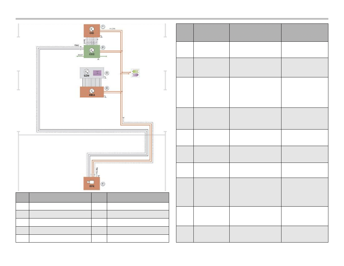
Index
Explanation
Index
Explanation
1
Central information display
6
Video module
2
Car communication computer
K-CAN
Body CAN
3
Center console switch cluster
LVDS
LVDS data line
4
Automatic climate control
FBAS
CVBS line
5
Rear-view camera
MOST
Media Oriented System Transport
Basic Functions of the Rear-view Camera System
The basic function of the rear-view camera system is to record
optically a wide-angle view (about 120°) of the area behind the
vehicle. The image is recorded via the lens in the rear-view camera
system and then transmitted in electronically conditioned form to
the car communication computer (CCC).
The video picture is transmitted via a video interface (CVBS, RGB).
Communication for controlling the system in the entire vehicle and
connection to the overall-bus system are effected via a K-CAN
interface.
In addition, the rear-view camera system serves to show further
assorted assistance information in the form of superimposed over-
lays (graphics and text) in the output signal (superimposed with the
real camera picture).
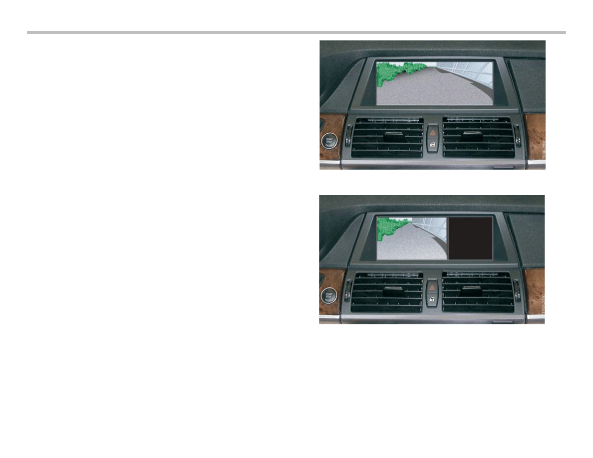
Image Reproduction Functions
The rear-view camera system shows the view of the area behind
the vehicle with a horizontal aperture angle of 120° on the central
information display. The view can be shown on the navigation dis-
play in two modes:
24
E70 General Vehicle Electronics Workbook
Full image view 620x240 pixels
Main window view 400x240 pixels
E70 General Vehicle Electronics Workbook
25
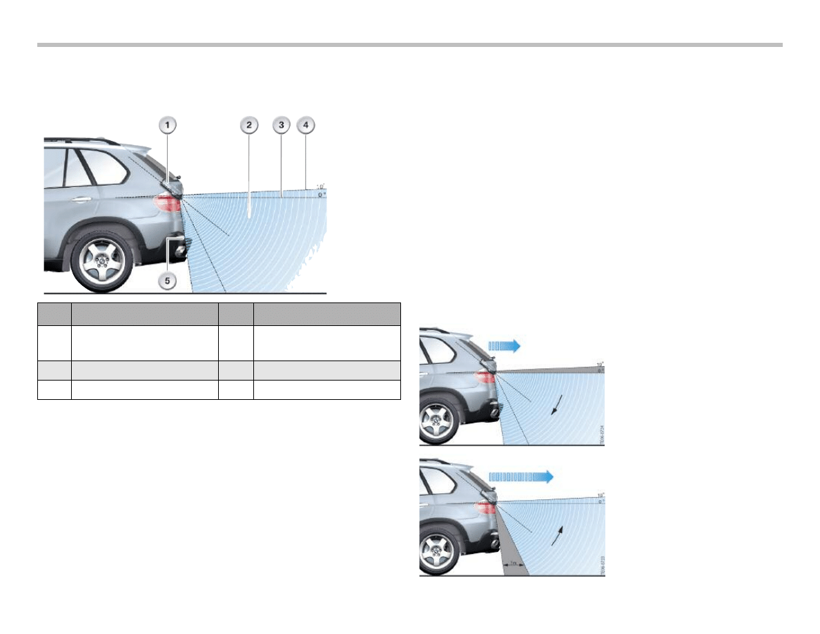
Lens Coverage Alignment
The entire coverage area of the rear-view camera system ranges
from the bumper at the bottom up to an angle of 10° from the hori-
zontal at the top.
Electronic Image Equalization
The rear-view camera features an electronic image equalizer that
corrects the distortions in vertical and horizontal correction caused
by the principle of the wide-angle lens. The equalization algorithm
must be such that the secondary effects such as information loss
in the form of blurred edges as well as distortion that occurs as part
of the equalization process are minimized.
The aim is to achieve the most realistic representation of the view
of the area behind the vehicle that can be unmistakably interpreted
by the driver.
View of Image Section
The Rear-view camera system always provides a view of a certain
section of the overall image. This makes it possible to adapt to the
external conditions of the vehicle. If the vehicle is parked on uneven
ground so that it is not straight, the Rear-view camera system can
adapt the video image corresponding to the incoming information.
This function is required for realizing the functions described in
the following:
• Virtual camera pan
• Image adaptation to vehicle inclination
• Software-based system calibration
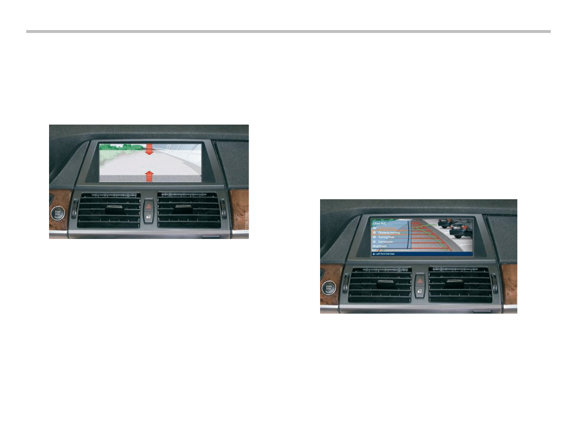
Virtual Camera Pan
Different areas are shown on the screen in vertical direction
depending on the driving speed.
The bottom area of the image
(from the bumper up to the
horizontal) is shown when
rear-view at slow speed
(up to about 3 mph).
Increasingly only the upper
area of the image (from about
1m distance from the vehicle
up to a minimum angle of 10°
above the horizontal) is shown
on the screen when rear-view
at faster speed (more than
3 mph).
Index
Explanation
Index
Explanation
1
Rear-view camera system
4
Maximum possible upward cover-
age range (10° upward from the
horizontal)
2
Coverage range
5
Rear bumper
3
Horizontal
26
E70 General Vehicle Electronics Workbook
Camera Pan as a Function of Speed
The camera pans virtually without the camera moving mechanically.
This function gives the driver a view of the area behind the vehicle
adapted to the current speed. When driving at slow speed, the area
very close to the rear of the vehicle is shown so that every detail
can be recognized. At speeds above 3 mph, the upper section of
the image is shown to provide an extended view.
Additional Functions of the Rear-view
Camera System
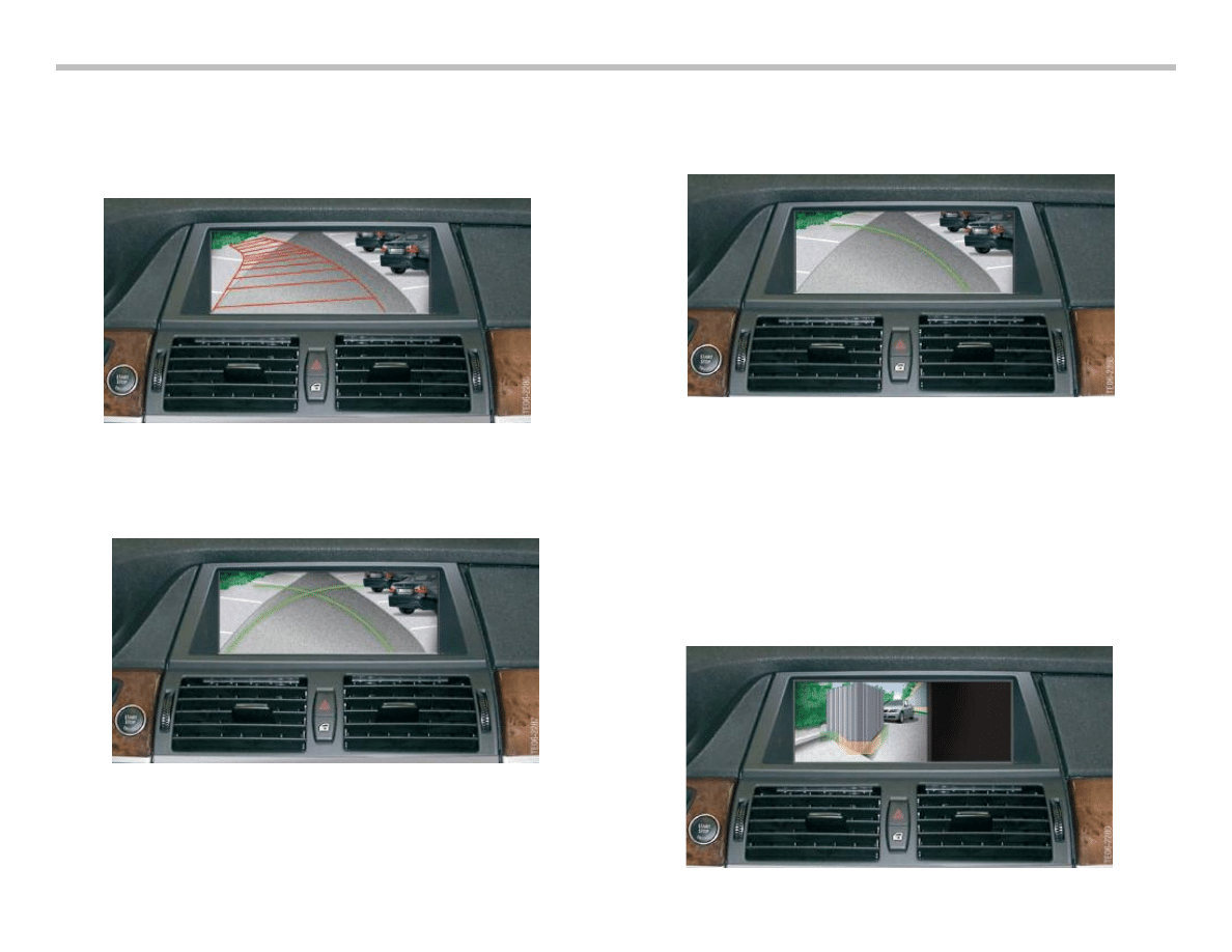
Assistance Graphics in Camera Image
Assistance graphics are superimposed on the camera image to
help the driver to park into spaces and maneuver.
The following assistance graphics can be superimposed:
• Lane help lines
• Turning circle lines
• Obstacle markings
• Zoom of towing hitch
Note: The brightness can be adjusted or the image
completely switched off
E70 General Vehicle Electronics Workbook
27
Lane Help Lines
The lane help lines are used to show the predicted path of the
vehicle and therefore the required maneuvering space depending
on the current position of the steering wheel. The lane help lines
are deactivated automatically when driving in forward direction.
Turning Circle Lines
The turning circle lines mark the minimum possible vehicle turning
circle. These marks remain superimposed on the image also when
driving in forward direction.
Only the relevant turning circle line is shown as soon as the driver
turns the steering wheel. The opposite turning circle line is blanked
out depending on the steering lock and is no longer shown at full
lock.
Obstacle Markings
Obstacle markings shown in the real camera image are partly trans-
parent overlays true to scale of the obstacle detected by the PDC.
The obstacle distribution in the area behind the vehicle is shown as
a 3D graphic. Its form, position and color depend on the distance to
each of the four PDC sensors in the bumper. Through correspon-
ding visualization with form and color, the way the obstacle mark-
ings are represented gives the driver a spatial perspective of the
obstacle distribution about the area behind the vehicle. The view
corresponds to the virtual PDC view.

Personal Profile
The settings last made by each user are stored in the Rear-view
camera system and retrieved after corresponding identification.
The following setting options can be stored in the rear-view cam-
era depending on the vehicle key.
• Display format (full image, main window as well as
permanently switch on/off camera image)
• Lane help lines (ON/OFF)
• Turning circle lines (ON/OFF)
• Obstacle markings (ON/OFF)
• Camera pan (ON/OFF)
• Image brightness (brightness value)
System Activation
System activation by driver The Rear-view camera system can be
activated by the driver by pressing the parking aid button (PDC
button) as from terminal 15. The system can no longer be activat-
ed at a speed higher than 12 mph
Automatic System Activation
Initially, the Rear-view camera system is ready to send data after
engaging reverse gear (identification by CAN messages) and then
sends an enquiry to the CCC. In response, the CCC gives the
authorization to output the video signal. The rear-view camera
video signal is output only after receiving this authorization.
A corresponding error message is sent in the form of a CC mes-
sage in the event of the Rear-view camera system not being avail-
able.
System Deactivation
Automatic or Indirect System Activation.
The rear-view camera is deactivated automatically in response
to the following conditions:
• After exceeding a certain preset speed Vmax - forward
(about 12mph) as well as
• A preset distance (about 50m) when driving in forward
direction.
Deactivation by Vehicle User
Deactivation by vehicle user (while image from the rear-view
camera is shown on the CID) by:
• Operating iDrive (pop-up menu)
• Pressing the PDC button
The rear-view camera is activated again when reverse gear is
engaged.
Permanent System Deactivation
The rear-view camera can be permanently deactivated in the
settings menu.
28
E70 General Vehicle Electronics Workbook
E70 General Vehicle Electronics Workbook
29
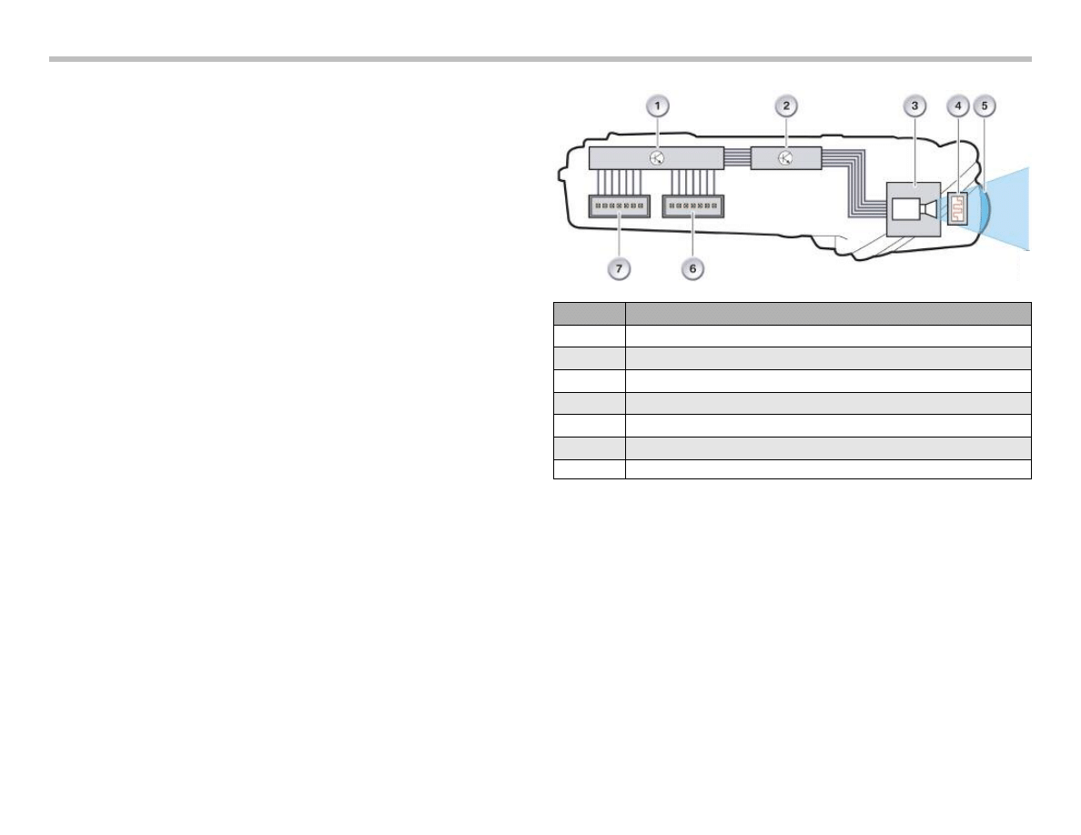
Rear-View Camera Design
The rear-view camera is based on a CMOS sensor
(Complementary Metal Oxide Semiconductor sensor) adapted for
use in the vehicle with an integrated image processing unit for full-
digital processing of the raw sensor data (up to 110 Mbits/s). The
electronic circuitry is designed as a two-processor system. The
image processing takes place in the electronic module. The follow-
ing processing steps are executed:
• Histogram control - brightness and color adaptation to various
exposure scenarios
• Image equalization - compensation of lens effects
• Superimposition of driver assistance line and camera pan
• Calibration functions
The tasks of bus communication, flash and boot routines and other
standard applications are implemented in a separate microproces-
sor.
The lens with the 2.0 shutter is made up of 6 glass lenses.
It contains an automatically controlled heating element to de-ice
the lens in winter. The heating element is largely controlled infinite-
ly variable with a PWM control.
Index
Explanation
1
Processor for bus communication, flash and boot routines
2
Processor for all image conditioning functions
3
CMOS image sensor
4
Heater
5
Lens
6
Power supply and bus link connector
7
Signal output connector
30
E70 General Vehicle Electronics Workbook
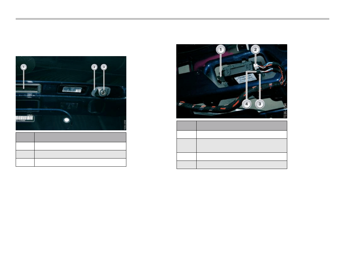
Location of Rear-view Camera
The Rear-view camera system is installed on the right in the tailgate
next to the tailgate lock. Tailgate seal A rubber seal seals off the
housing of the rear-view camera from the tailgate.
Mounting in the Tailgate
The rear-view camera is installed from the rear of the tailgate
and secured to the housing by means of two screws.
Temperature-controlled Lens Thawing
In freezing conditions, the camera lens is heated and thawed
automatically to keep it free of snow and ice.
Calibration of the Rear-view Camera
In order to maintain the accuracy of the rear-view camera, a calibra-
tion procedure must followed as per the latest BMW Service infor-
mation found in TIS or on the GT-1.
Index
Explanation
1
Mounting screw
2
Connector, white (power supply
and bus connection)
3
Mounting screw
4
Connector, black (video signal)
Index
Explanation
1
Tailgate handle
2
Rear-view camera seal
3
Rear-view camera lens

E70 General Vehicle Electronics Workbook
31
1) What is the special tool part number used for the rear view
camera adjustment?
2) Write the path used to locate the service function for adjusting
the rear view camera.
3) When is the rear view camera adjustment required?
4) When is the rear view camera adjustment required?
Workshop Exercise - Rear View Camera Adjustment
Using an instructor assigned E70 vehicle, adjust the rear view camera through the test plan outlined in the diagnostic equipment.
32
E70 General Vehicle Electronics Workbook
The anti-theft alarm system (DWA) is available as standard equip-
ment. The task of the anti-theft alarm system is to indicate unau-
thorized access to the vehicle by emitting an alarm. The alarm can
be triggered both audibly and visually. To do this, however, the
alarm system must be armed. When activated, the alarm monitors
the entire vehicle interior.
In addition, the alarm system monitors the engine compartment
and the vehicle's rest position. In order that nothing can be stolen
from the luggage compartment, the alarm system monitors the
tailgate.
The alarm also indicates if the vehicle has been tampered with like
cutting the feed line to the emergency siren.
The anti-theft alarm system is based on the E90. However, the
alarm system's ultrasonic passenger-compartment sensor is
located fully in the roof function center.
The ultrasonic signal passes into the inside of vehicle through
openings in the grill of the roof function center. The emergency
power siren with tilt alarm sensor is located near the front wheel
arch.
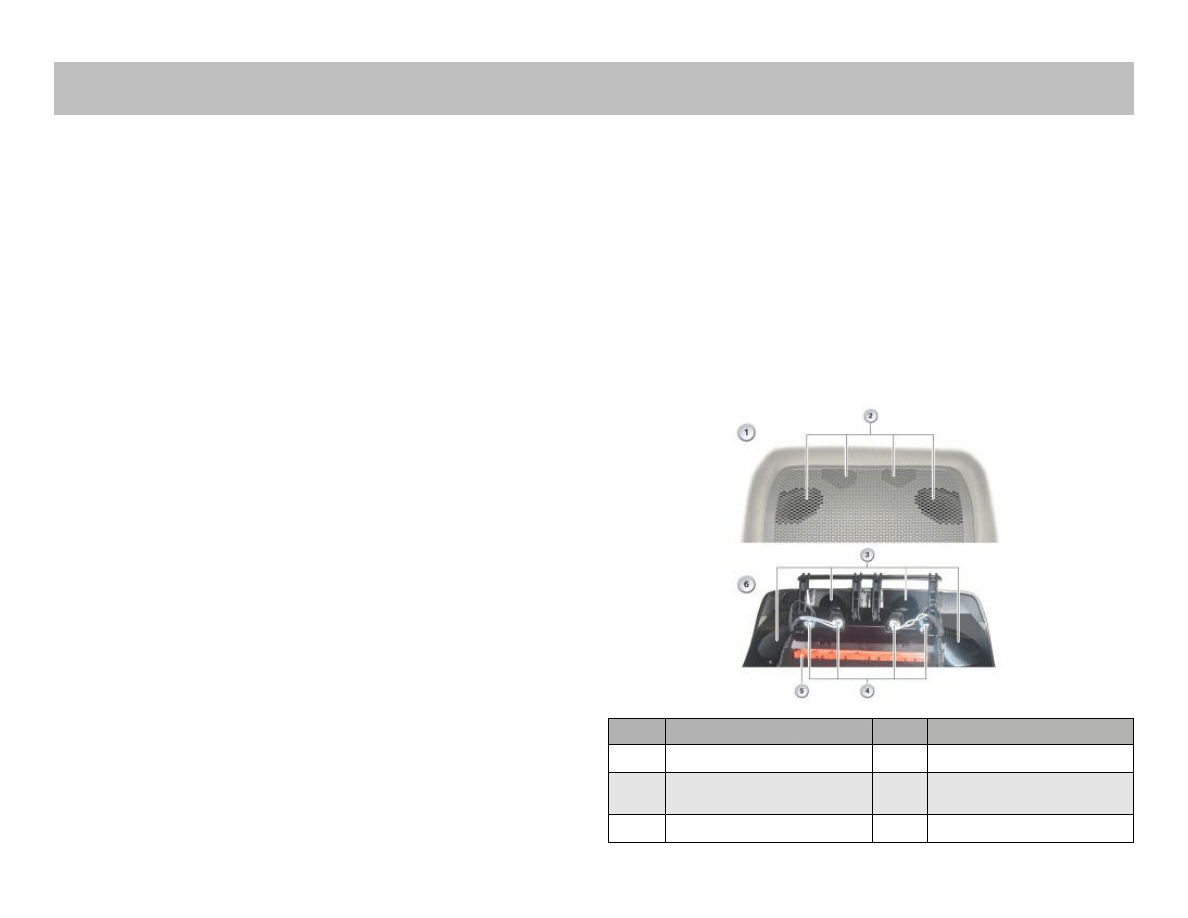
Ultrasonic Passenger Compartment Protection
The ultrasonic passenger-compartment sensor captures and eval-
uates movements in the vehicle interior. Initialization of the ultra-
sonic passenger-compartment sensor is started 3 s after closing
the engine bonnet, tailgate and the last door.
The ultrasonic passenger-compartment sensor is operational 20 s
after the start of initialization and is included in the vehicle moni-
toring system. The ultrasonic passenger compartment sensor has
been integrated into the roof function center. The roof function
center is connected to the K-CAN and DWA bus.
Ultrasonic Passenger Compartment Protection
Index
Explanation
Index
Explanation
1
Front of roof function center
4
Ultrasonic sensor
2
Exit openings of
ultrasonic sensors
5
Roof function center connector
3
Funnel for ultrasonic sensors
6
Rear of roof function center
Anti-Theft Alarm System
Document Outline
- Main Menu
- E70 Introduction
- E70 Powertrain
- E70 Voltage Supply and Bus Systems
- E70 Chassis Dynamics
- E70 General Vehicle Electronics
- E70 Head-Up Display
- E70 Audio Systems
- E70 Climate Control
- E70 Passive Safety
Wyszukiwarka
Podobne podstrony:
40 0610 013 05 01 7 General arrangement
05 Integrated High Voltage Electronics to drive Microactuators
40 0610 013 05 01 7 General arrangement
Bearden EXPLANATION OF THE MOTIONLESS ELECTROMAGNETIC GENERATOR WITH 0(3) ELECTRODYNAMICS
2002 05 Szerokopasmowy generator KF
2008 05 Automatyczna generacja ciągów
British Patent 2,812 Improvements in Methods of and Apparatus for the Generation of Electric Current
James White SG 05 Sector General
06 E70 Head Up Display WB
Biomass Fired Superheater for more Efficient Electr Generation From WasteIncinerationPlants025bm 422
General Electric
Kolokwium 05 Wb 10.11, PWR, Inżynieria Środowiska, semestr 3, Chemia Wody
Pod Basrą zastrzelono generała policji (09 05 2009)
General Electric Plastics Guide Polycarbonate
Elektor Electronics 2007 05
EV (Electric Vehicle) and Hybrid Drive Systems
więcej podobnych podstron