Installation instructions
Residual engine heat utilization
83.4
Model 124 left-hand steering
(not for vehicles with stationary heater)
Procedure
All vehicles
1
Disconnect ground cable from battery.
Note:
Find out code for coded radio.
2
Remove both front foot mats.
3
Remove foot support in right front footwell.
4
Remove cover at bottom of right A-pillar.
5
Remove right bottom section of cover below
instrument panel.
6
Remove cover below instrument panel on
left (68-150).
7
Remove side paneling on left and right of
center console.
8
Remove instrument cluster.
9
Remove left side nozzle and left air hose.
a
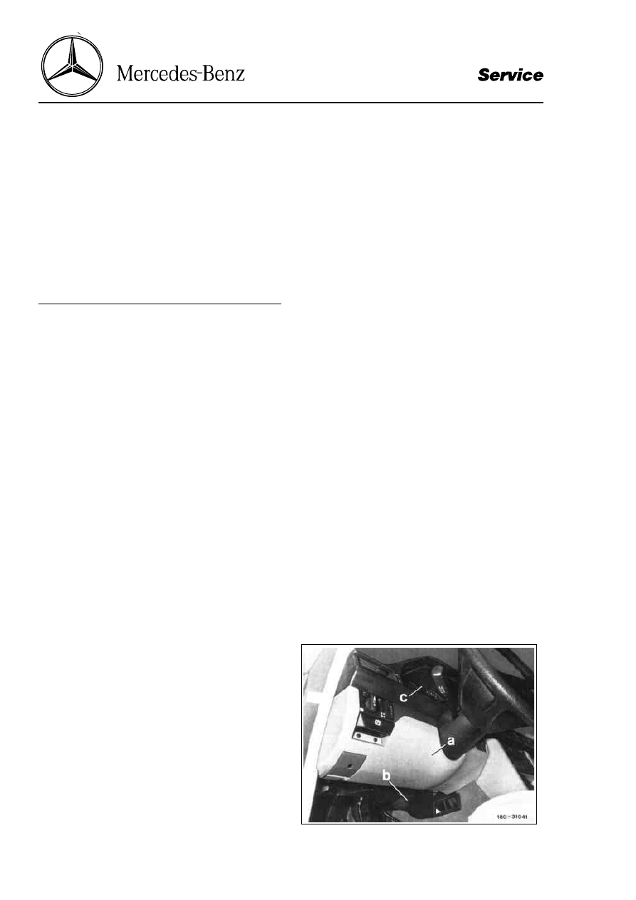
Cover, top section
b
Cover, bottom section
c
Instrument cluster
Strona 1/11
© Daimler AG, 12.07.12, G/03/09 / ea8304pb3es00x / 83.04 - Installation instructions: Residual engine heat utilization system Model 124.1/3, LHD (except for vehicles with stationary heater)
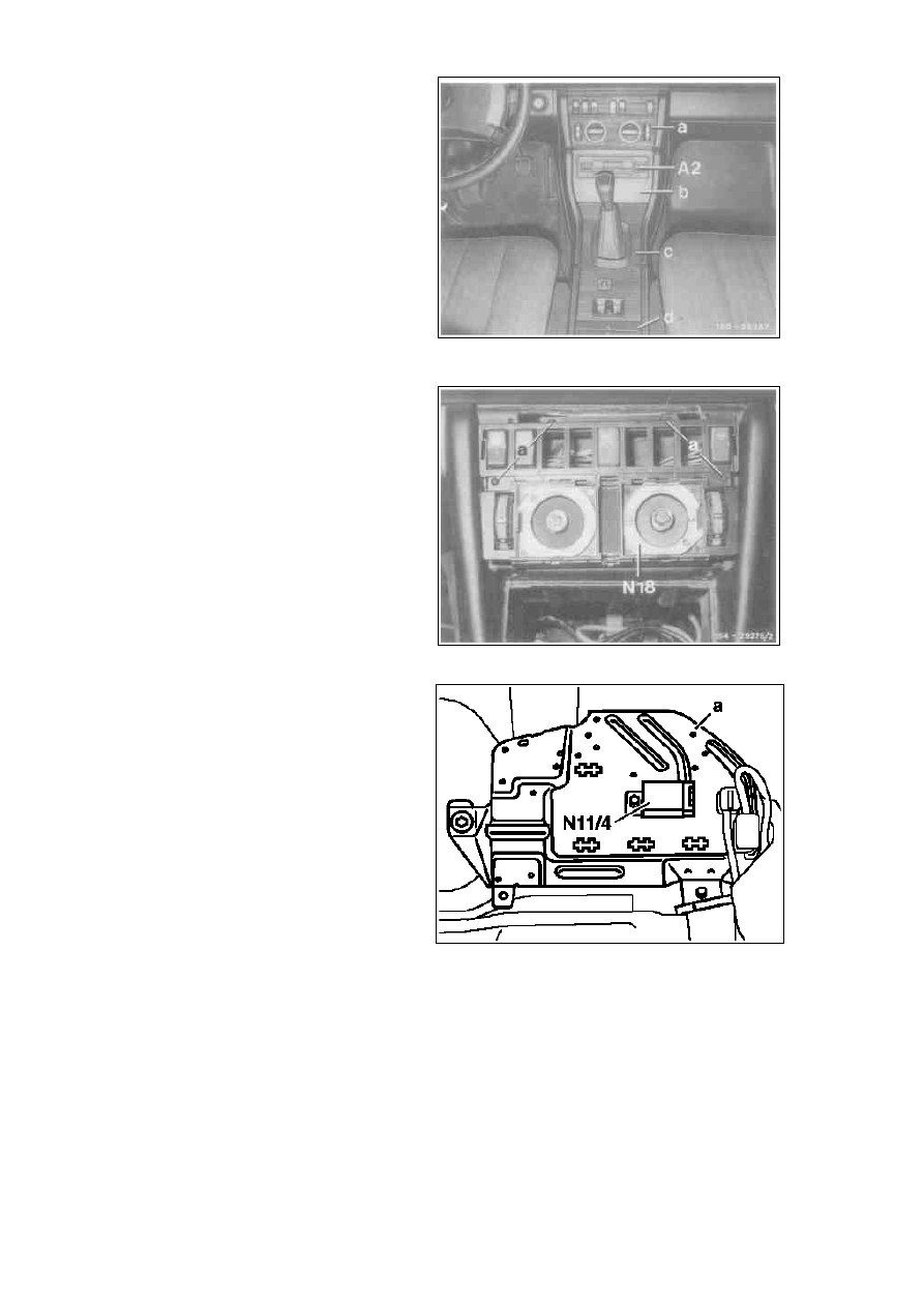
10 Remove cover on radio or two-way radio,
remove radio and cover on heater control.
A2
Radio
a
Cover on heater control
b
Cover on two-way radio
11 Loosen pushbutton control module
(N18, N19/1 or N22) and put down at side.
N18
Heater pushbutton control module
a
Screw
12 Screw REST time-limit relay module (N11/4)
to hole present in support plate with sheet
metal screw.
a
Support plate
N11/4
REST time-limit relay module
P83.75-0203-13
Strona 2/11
© Daimler AG, 12.07.12, G/03/09 / ea8304pb3es00x / 83.04 - Installation instructions: Residual engine heat utilization system Model 124.1/3, LHD (except for vehicles with stationary heater)
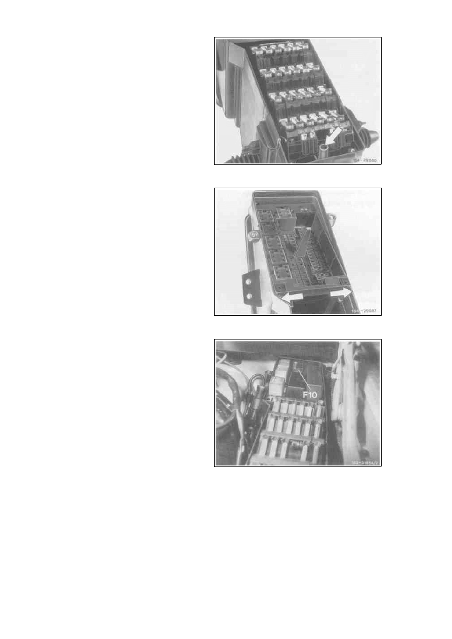
13 Remove cover from fuse and relay box
(6 screws), loosen fuse carrier (arrow) and put
down at side.
14 Loosen relay holder and put down at side.
For this purpose press fuse and relay box
apart (arrows).
15 Clip connector for wiring harness auxiliary
fuse holder (engine residual heat utilization
system) into relay box section F.
16 Attach auxiliary fuse holder to connector in
section F and insert 16 A fuse into circuit 4.
Location of auxiliary fuse holder (F10)
16
Amperes (circuit 4)
Strona 3/11
© Daimler AG, 12.07.12, G/03/09 / ea8304pb3es00x / 83.04 - Installation instructions: Residual engine heat utilization system Model 124.1/3, LHD (except for vehicles with stationary heater)
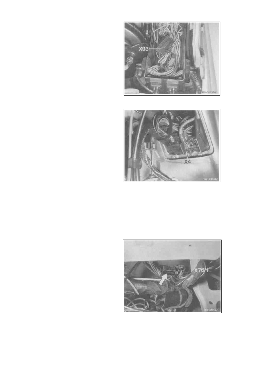
17 Disconnect black/pink wire or wires (with
sliding roof) from fuse 7 (output) and connect
black/red wire from auxiliary wiring harness
in their place. Connect previously
disconnected black/pink wire from auxiliary
wiring harness to 1-pin connector (X93).
X93
Tempmatic A/C terminal block
(REST)
18 Connect red wire from auxiliary wiring
harness to terminal block (X4) circuit 30.
19 Install fuse carrier and cover for fuse and
relay box.
X4 Terminal block, circuit 30, relay/fuse box
On vehicles with automatic air conditioning
items 20-23 are eliminated.
20 Disconnect connector for blower motor
preresistor group (R14, arrow) and open.
21 Remove green/blue wire from connector pin 1
and replace with plug sleeve for green wire
from auxiliary wiring harness.
22 Close connector and plug back into
preresistor group.
X76/ 1
Air volume switch connector (REST) (1-pin)
Strona 4/11
© Daimler AG, 12.07.12, G/03/09 / ea8304pb3es00x / 83.04 - Installation instructions: Residual engine heat utilization system Model 124.1/3, LHD (except for vehicles with stationary heater)
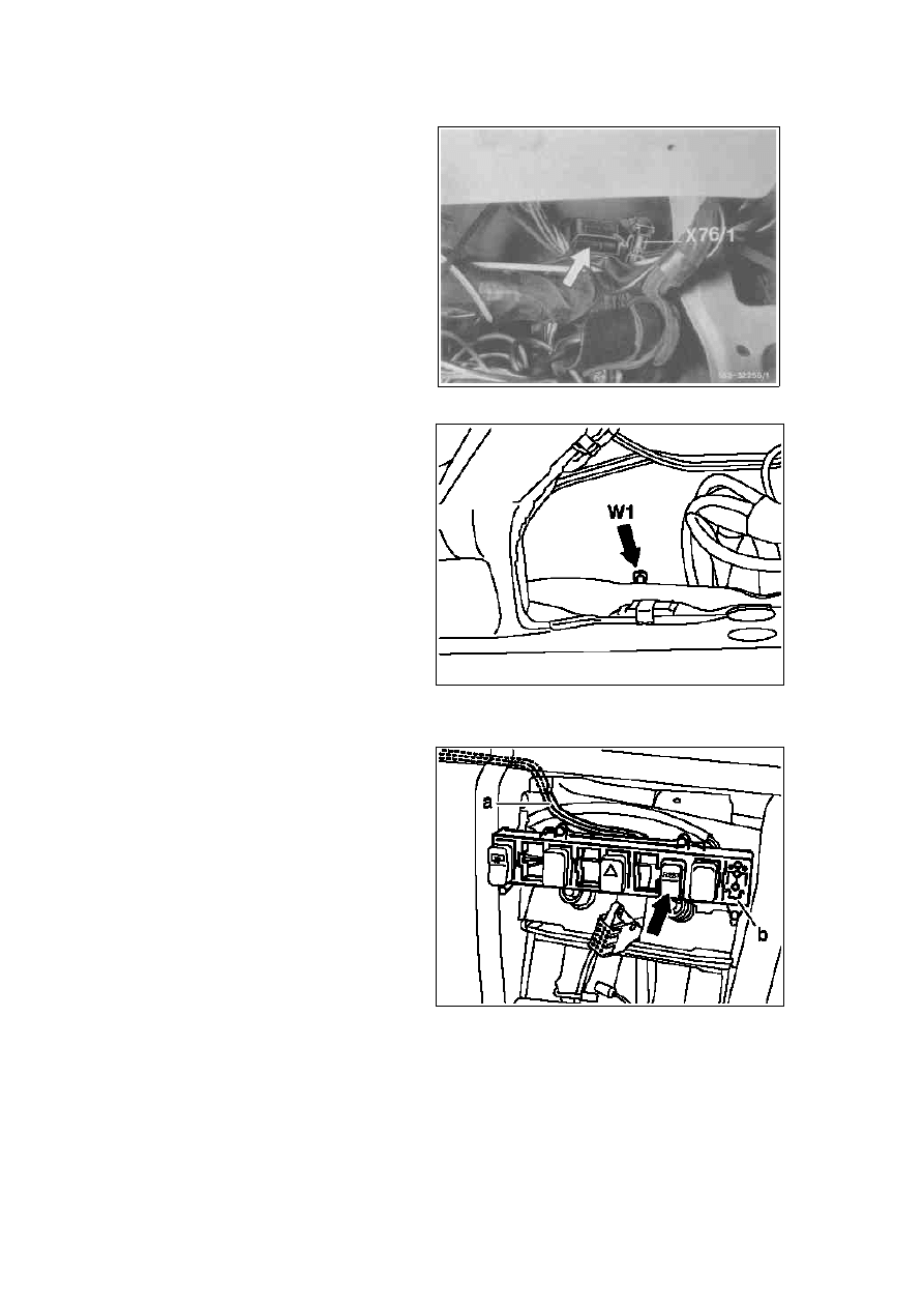
23 Install connector housing on green/blue wire
removed and connect with round plug on
green/blue wire from auxiliary wiring harness
(connector X76/1).
X76/ 1
Air volume switch connector
(REST) (1-pin)
24 Connect brown wire from auxiliary wiring
harness to main ground point (W1).
W1
Main ground
(behind instrument cluster)
P83.75-0204-13
25 Route auxiliary wiring harness to center
console so that it cannot chafe. Tie down as
required.
26
Unclip switch mount grate. Clip in 6-pin
connector (arrow) for auxiliary wiring
harness. Attach switch (S46/3) and
reinstall switch mounting grate.
a
Auxiliary wiring harness
b
Switch mounting grate
P83.75-0200-13
Strona 5/11
© Daimler AG, 12.07.12, G/03/09 / ea8304pb3es00x / 83.04 - Installation instructions: Residual engine heat utilization system Model 124.1/3, LHD (except for vehicles with stationary heater)
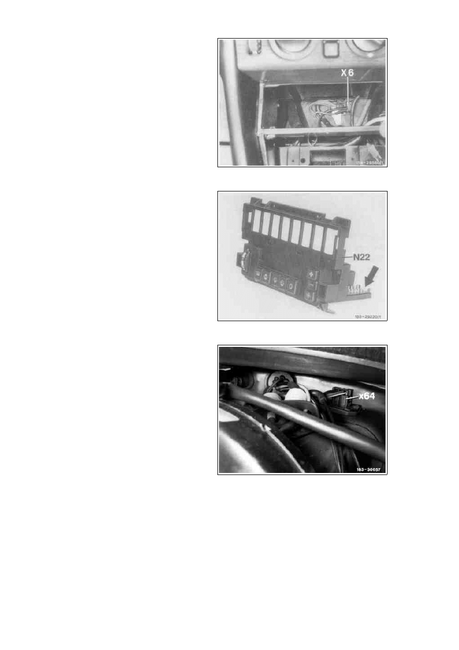
27 Connect grey/blue wire from auxiliary wiring
harness to terminal block (X6).
X6
Terminal block, circuit 58d
Only with automatic A/C
28 Disconnect right connector (arrow) from
pushbutton control module and insert green
wire from auxiliary wiring harness into vacant
chamber 13 on connector. Then reinstall
connector.
N22 A/C pushbutton control module
(automatic A/C)
29 Route tie-out from wiring harness with 3-pin
intermediate connector to blower regulator/
interior harness connector (X64).
X64 Blower regulator/interior harness
connector
Strona 6/11
© Daimler AG, 12.07.12, G/03/09 / ea8304pb3es00x / 83.04 - Installation instructions: Residual engine heat utilization system Model 124.1/3, LHD (except for vehicles with stationary heater)
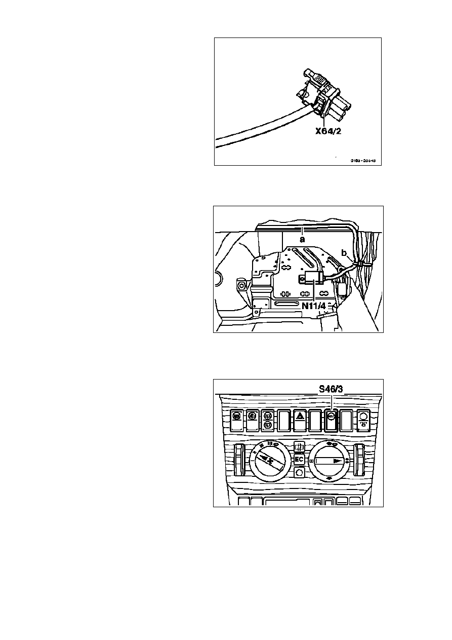
30 Disconnect connector from blower regulator/
interior harness connector (X64). Connect
intermediate connector from auxiliary wiring
harness and connector to intermediate
connector.
X64/2
REST blower regulator
intermediate connector
All vehicles
31 Lay auxiliary wiring harness to front right
footwell, connect to time-limit relay module
and fasten with present cable strap.
32 Install foot support.
a
Auxiliary wiring harness
b
Cable strap
N11/ 4
REST time-limit relay module
P83.75-0202-13
33 Cut out hole for switch in cover or use new
cover with switch cutout.
S46/3
REST pushbutton switch
P83.75-0201-13
34 Install instrument cluster
35 Install air nozzle and air hose.
36 Install pushbutton control module
(N18, N19/1 or N22).
37 Install all panels and covers removed.
38 Reconnect ground lead to battery.
39 Check for proper function.
Strona 7/11
© Daimler AG, 12.07.12, G/03/09 / ea8304pb3es00x / 83.04 - Installation instructions: Residual engine heat utilization system Model 124.1/3, LHD (except for vehicles with stationary heater)
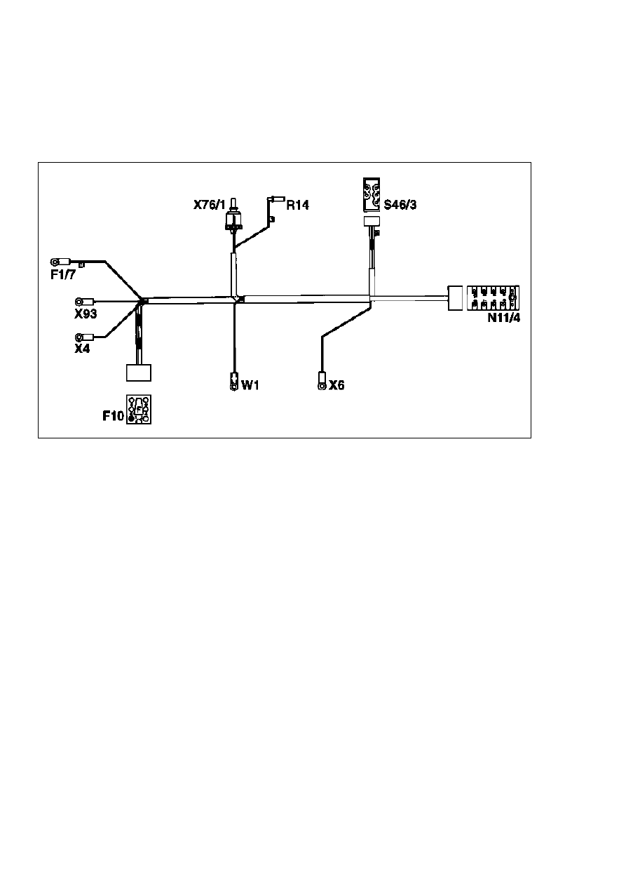
P83.75-0206-55
Wiring harness for residual engine heat utilization system with automatic heater (HEAT) and air
conditioning (Tempmatic)
Fuse and relay box
Terminal block (circuit 30, fuse and relay box)
F1/ 7
X4
Fuse 7 (black/red wire)
(red wire)
Auxiliary fuse holder (HEAT)
F10
X6
Terminal block (circuit 58d) (2-pin)
(grey/blue wire)
REST time-limit relay module
N11/ 4
X76/ 1
Air volume switch connector (REST) (1-pin)
Blower motor preresistor group
R14
(green wire)
X93
Tempmatic A/C terminal block (REST) (black/
REST pushbutton switch
S46/ 3
pink wire)
W1
Main ground (behind instrument cluster)
(brown wire)
Strona 8/11
© Daimler AG, 12.07.12, G/03/09 / ea8304pb3es00x / 83.04 - Installation instructions: Residual engine heat utilization system Model 124.1/3, LHD (except for vehicles with stationary heater)
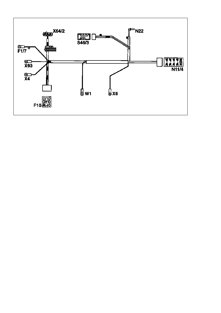
P83.75-0207-55
Wiring harness for residual engine heat utilization system with air conditioning (automatic)
Fuse and relay box
Terminal block (circuit 30, fuse and relay box)
F1/ 7
X4
Fuse 7 (black/red wire)
(red wire)
Auxiliary fuse holder (HEAT)
F10
X6
Terminal block (circuit 58d) (2-pin)
(grey/blue wire)
REST time-limit relay module
N11/ 4
X64/ 2
REST blower regulator intermediate connector
A/C pushbutton control module (automatic (AC)
N22
(yellow wire)
X93
Tempmatic A/C terminal block (REST) (black/
REST pushbutton switch
S46/ 3
pink wire)
W1
Main ground (behind instrument cluster)
(brown wire)
Strona 9/11
© Daimler AG, 12.07.12, G/03/09 / ea8304pb3es00x / 83.04 - Installation instructions: Residual engine heat utilization system Model 124.1/3, LHD (except for vehicles with stationary heater)
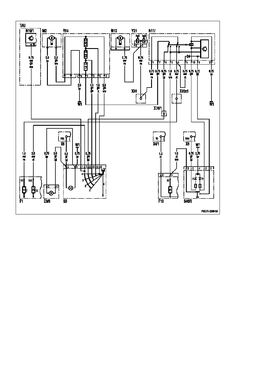
P83.75-0208-59
Wiring diagram, residual engine heat utilization system with automatic heater (HEAT) and air
conditioning (Tempmatic)
Air volume switch illumination
E9/6
S46/3
REST pushbutton switch
Fuse and relay box
F1
W1
Main ground (behind instrument cluster)
Fuse 7, circuit 15
F1-7
X4/1
Terminal block (circuit 30, interior)
Fuse 12, circuit 15X
F1-12
X6
Terminal block (circuit 58d) (2-pin)
Auxiliary fuse holder (HEAT)
F10
X76/1
Air volume switch connector (REST) (1-pin)
Blower motor
M2
X93
Tempmatic A/C terminal block (REST), 1-pin
Coolant circulation pump
M13
X93x1
Tempmatic A/C terminal block connector (REST)
REST time-limit relay module
N11/4
Y21
Duovalve
A/C pushbutton control module (Tempmatic A/C)
N19/1
Blower motor preresistor group
R14
Blower switch
S3
Strona 10/11
© Daimler AG, 12.07.12, G/03/09 / ea8304pb3es00x / 83.04 - Installation instructions: Residual engine heat utilization system Model 124.1/3, LHD (except for vehicles with stationary heater)
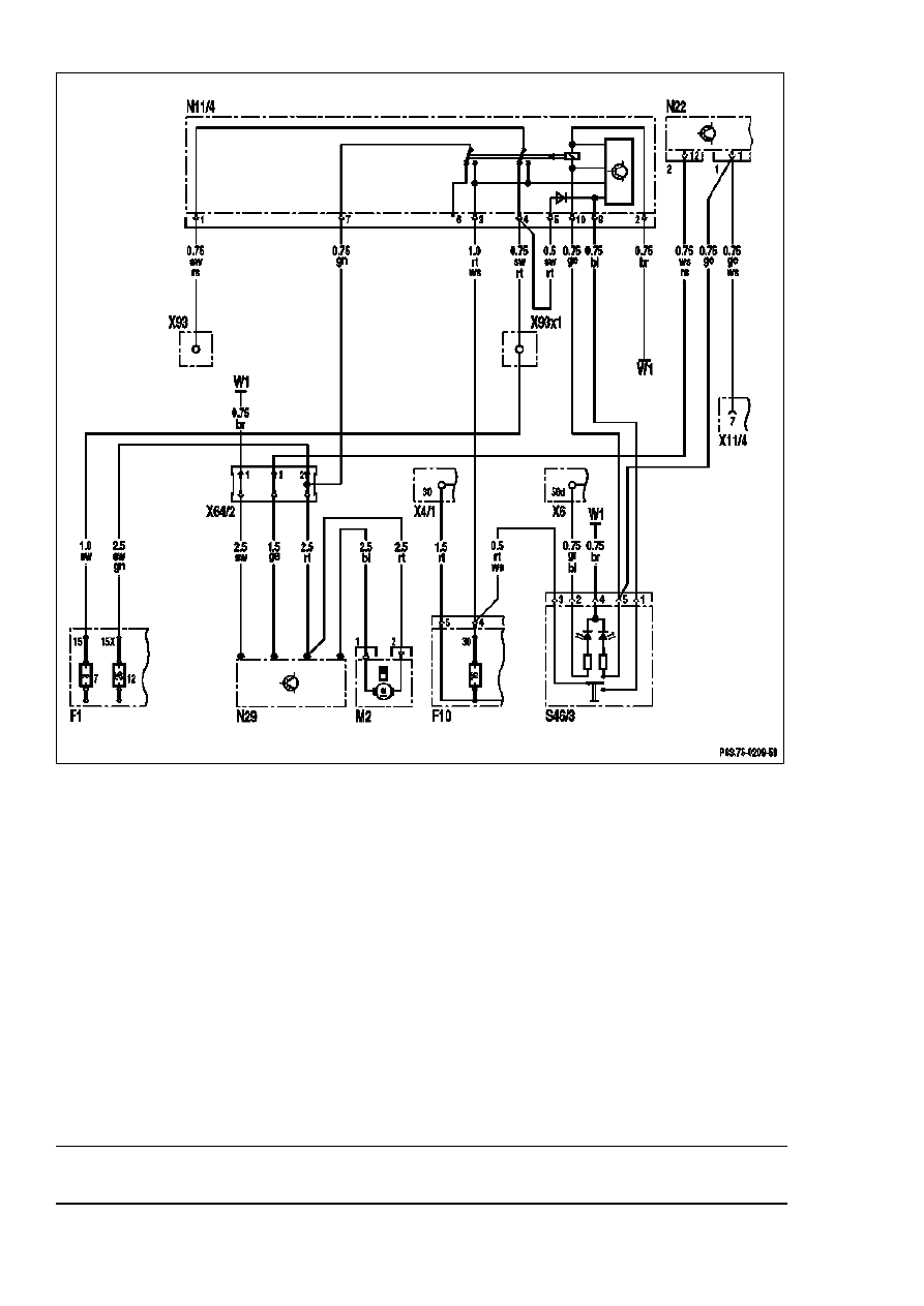
P83.75-0209-59
Wiring diagram, residual engine heat utilization system with air conditioning (automatic)
Fuse and relay box
F1
W1
Main ground (behind instrument cluster)
Fuse 7, circuit 15
Terminal block (circuit 30, interior)
F1-7
X4/1
Fuse 12, circuit 15X
Terminal block (circuit 58d) (2-pin)
F1-12
X6
Auxiliary fuse holder (HEAT)
F10
X11/4
Data link connector
Blower motor
M2
X64/2
REST blower regulator intermediate connector
REST time-limit relay module
N11/4
X93
Tempmatic A/C connector (REST), 1-pin
A/C pushbutton control module (automatic A/C)
N22
X93x1
Tempmatic A/C terminal block connector (REST)
Electric blower regulator
N29
S46/3
REST pushbutton switch
Parts ordering note
The parts required for installation are given in the following parts documents:
Kit
SA 56.547
Strona 11/11
© Daimler AG, 12.07.12, G/03/09 / ea8304pb3es00x / 83.04 - Installation instructions: Residual engine heat utilization system Model 124.1/3, LHD (except for vehicles with stationary heater)
Wyszukiwarka
Podobne podstrony:
Instruktaż obsługa instalacji i urządzeń elektroenergetycznych
01-WZÓR-Instr. eksploatacji instalacji i urządzeń elektroen~2, Instrukcje BHP, XXXV - INSTR. ENERGET
Instruktaż obsługa instalacji i urządzeń elektroenergetycznych
Instrukcja instalacji esf
instrukcja instalacji i obsługi interfejsu
Honda EPC instrukcja instalacji
Instrukcja instalacji siateczki (bubble breaker)
33 Schemat elektryczny FM445 id Nieznany (2)
Instrukcja instalacji spolszczenia INPA
instalacje i oświetlenie elektryczne opracowanie pytań na egzamin
opracowania ochr oddzial ciepln instal el, Elektryka w budownictwie
Instrukcja instalacji rejestracji EPLAN PL
Instrukcja Instalacyjna NVB A PL (2)
instrukcja instalacji
Instrukcja instalacji sterownika LAN
CA 6 instrukcja instalatora
opracowania wym zabezp instal el, ELEKTRYK
więcej podobnych podstron