
Building a Home
Building a Home
-
-
Scale
Scale
Vertical Axis Wind Turbine
Vertical Axis Wind Turbine
John Dellaport
John Dellaport
University of Colorado
University of Colorado
–
–
Denver
Denver
April 11, 2005
April 11, 2005

OBJECTIVES
OBJECTIVES
Build a vertical axis wind turbine (VAWT) to
Build a vertical axis wind turbine (VAWT) to
provide power for lighting a small home
provide power for lighting a small home
Experiment with different materials and
Experiment with different materials and
designs to maximize power production and
designs to maximize power production and
minimize generator cut
minimize generator cut
-
-
in speeds
in speeds
Select commonplace materials, tools and
Select commonplace materials, tools and
methods so that VAWT can be constructed
methods so that VAWT can be constructed
by those with limited resources and
by those with limited resources and
experience
experience
Two Design Types
Two Design Types
3
3
-
-
Level
Level
Savonius
Savonius
Rotor
Rotor
(S
(S
-
-
Rotor)
Rotor)
Universal Axis Helical
Universal Axis Helical
Turbine (UAHT)
Turbine (UAHT)
(covered
(covered
separately)
separately)
Two S
Two S
-
-
Rotor Designs
Rotor Designs
1)
1)
Plastic/Steel
Plastic/Steel
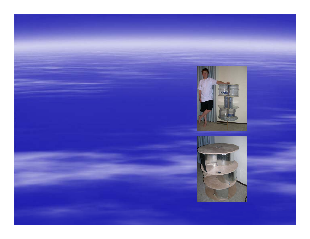
2)
2)
Steel/Wood
Steel/Wood

Materials
Materials
-
-
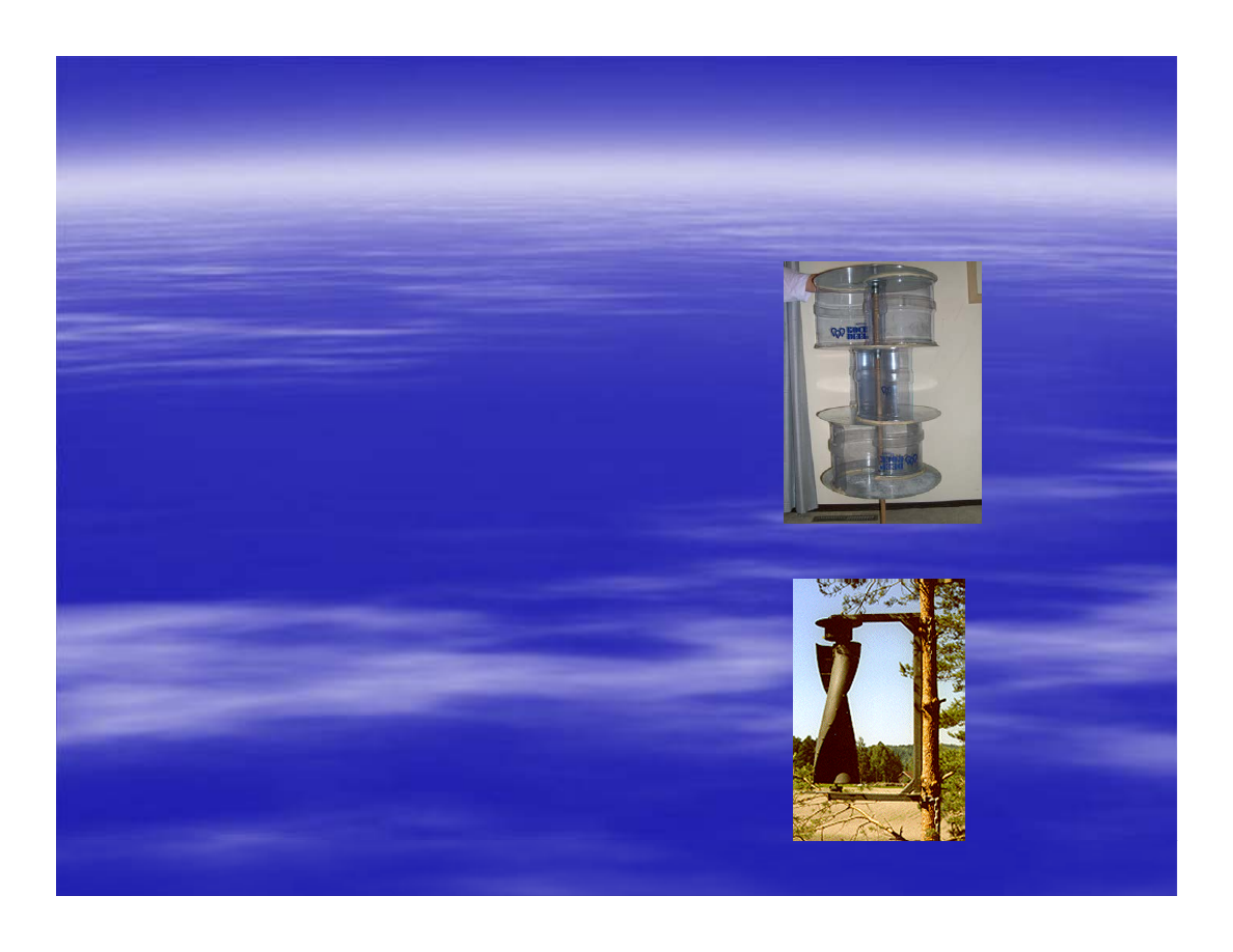
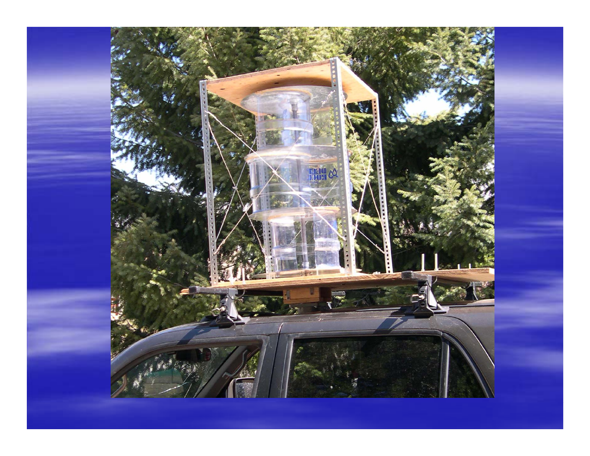
Plastic/Steel Rotor
Plastic/Steel Rotor
Rotor
Rotor
–
–
One 16
One 16
-
-
ga.
ga.
galv
galv
. sheet metal (4’x4’) (end caps)
. sheet metal (4’x4’) (end caps)
–
–
Three 5
Three 5
-
-
gallon plastic water bottles (vanes)
gallon plastic water bottles (vanes)
–
–
Two ¾” floor flanges
Two ¾” floor flanges
–
–
One 3” long ¾” nipple
One 3” long ¾” nipple
–
–
Two ¼” set screws
Two ¼” set screws
–
–
One ¾”
One ¾”
diam
diam
. X 3’ long steel keyed shaft and key
. X 3’ long steel keyed shaft and key
–
–
Two ¾” flanged, sealed bearings
Two ¾” flanged, sealed bearings
–
–
Adhesive (“Liquid Nails”)
Adhesive (“Liquid Nails”)
–
–
Screws, nuts and washers (flanges and bearings)
Screws, nuts and washers (flanges and bearings)

Materials
Materials
-
-
Plastic/Steel Rotor (cont.)
Plastic/Steel Rotor (cont.)
Framework
Framework
–
–
One 2’x4’ sheet 3/4” pressure
One 2’x4’ sheet 3/4” pressure
-
-
treated plywood
treated plywood
–
–
25’ of stranded
25’ of stranded
galv
galv
. steel wire
. steel wire
–
–
12’ of slot angle steel
12’ of slot angle steel
–
–
1 1/2”
1 1/2”
galv
galv
. lag screws (slot angle)
. lag screws (slot angle)
–
–
1” hose clamp
1” hose clamp
–
–
Shaft key
Shaft key

Tools Needed
Tools Needed
Required
Required
–
–
Wood and metal saws
Wood and metal saws
–
–
Drill and sharp metal bits (3/4” hole
Drill and sharp metal bits (3/4” hole
-
-
saw metal bit)
saw metal bit)
–
–
Hammer, pliers, wire cutters
Hammer, pliers, wire cutters
–
–
Wrench for lag screws
Wrench for lag screws
–
–
Phillips
Phillips
-
-
head screwdriver and Allen key wrench for set screws
head screwdriver and Allen key wrench for set screws
–
–
Tap (for threading nipple for set screws)
Tap (for threading nipple for set screws)
–
–
Measuring tape, 3’ length of string, nail, pencil or pen
Measuring tape, 3’ length of string, nail, pencil or pen
–
–
Utility knife and electrical tape
Utility knife and electrical tape
–
–
Safety equipment (safety glasses, ear plugs, leather gloves)
Safety equipment (safety glasses, ear plugs, leather gloves)
–
–
Carpenter’s square
Carpenter’s square
Optional
Optional
–
–
Caulking gun
Caulking gun
–
–
3’ long bar clamps
3’ long bar clamps
–
–
Thread cutting oil
Thread cutting oil
–
–
Pop rivet gun
Pop rivet gun

Needed Skills and Tips
Needed Skills and Tips
Skills
Skills
General construction experience
General construction experience
Specific experience with cutting, drilling and
Specific experience with cutting, drilling and
sanding wood and sheet metal
sanding wood and sheet metal
Tips to Ensure a Smooth
Tips to Ensure a Smooth
-
-
Rotating Turbine
Rotating Turbine
Measure and cut the rotor vanes precisely
Measure and cut the rotor vanes precisely
End caps must be parallel to each other and
End caps must be parallel to each other and
perpendicular to shaft, check the following…
perpendicular to shaft, check the following…
–
–
Vane heights are the same
Vane heights are the same
–
–
End caps are perpendicular to shaft
End caps are perpendicular to shaft
–
–
End caps are parallel to each other
End caps are parallel to each other
Rotor Instructions: Plastic/Steel
Rotor Instructions: Plastic/Steel
-
-
Rotor
Rotor
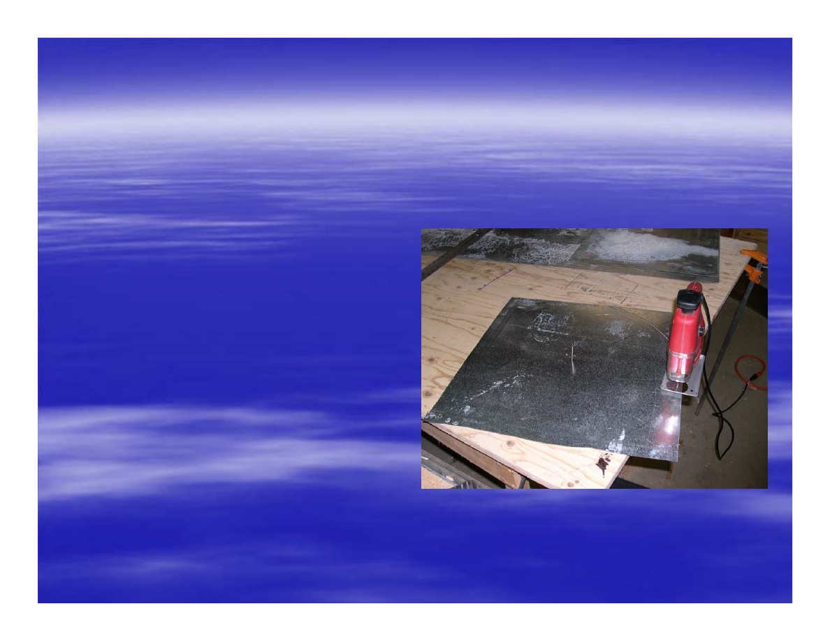
1) End Caps
1) End Caps
-
-
Cut four 18”
Cut four 18”
diam
diam
. discs from
. discs from
galv
galv
.
.
sheet using string and pen
sheet using string and pen
to scribe circles. Drill a ¾”
to scribe circles. Drill a ¾”
hole in center of each disc.
hole in center of each disc.
Drill holes and attach 2
Drill holes and attach 2
floor flanges over ¾” holes
floor flanges over ¾” holes
in centers of 2 discs. Cut
in centers of 2 discs. Cut
¾” nipple in half and tap
¾” nipple in half and tap
holes for set screws in
holes for set screws in
each nipple. Thread
each nipple. Thread
nipples into flanges and
nipples into flanges and
install set screws.
install set screws.

Rotor Instructions (cont.)
Rotor Instructions (cont.)
2) Vanes
2) Vanes
–
–
Wearing gloves, use utility knife to
Wearing gloves, use utility knife to
cut tops and bottoms off water bottles,
cut tops and bottoms off water bottles,
leaving 10” long straight sections in middle
leaving 10” long straight sections in middle
of bottles. Cut each straight section in half
of bottles. Cut each straight section in half
so that two U
so that two U
-
-
shaped sections are
shaped sections are
produced. There should be 6 vanes when
produced. There should be 6 vanes when
cutting is complete.
cutting is complete.
Rotor Instructions (cont.)
Rotor Instructions (cont.)
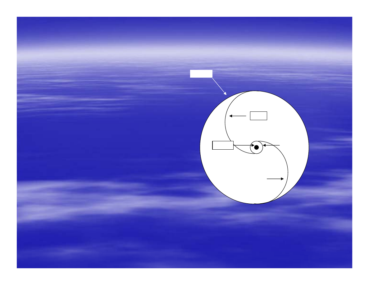
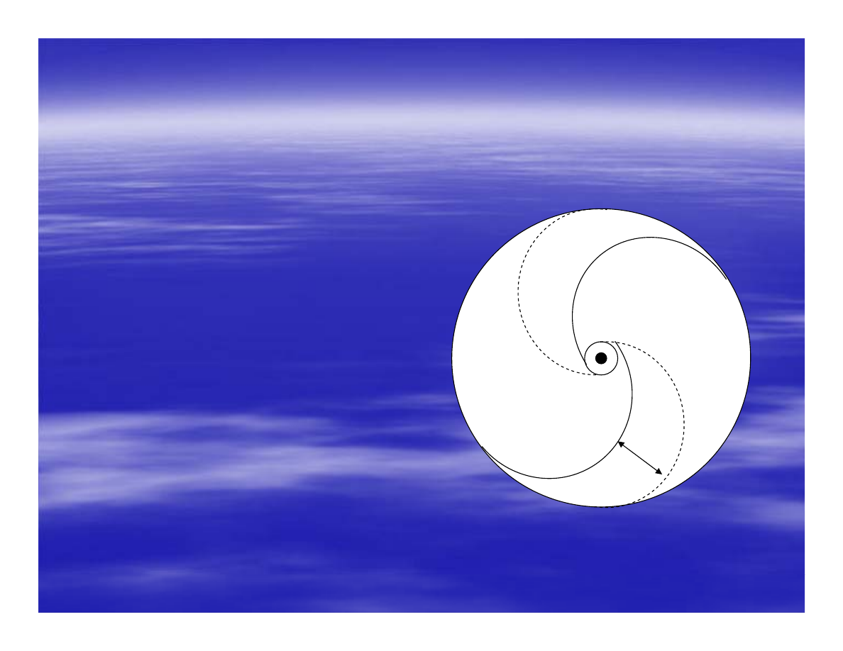
3) Assembly
3) Assembly
-
-
Slide the four
Slide the four
end caps onto ¾” steel
end caps onto ¾” steel
shaft making sure that the
shaft making sure that the
two flanged
two flanged
-
-
end caps are
end caps are
on either end of the shaft
on either end of the shaft
(flanges facing in). Leave a
(flanges facing in). Leave a
9” or 10” space between
9” or 10” space between
end caps. Tighten set
end caps. Tighten set
screws. Starting on 1
screws. Starting on 1
st
st
level, slide 2 vanes in
level, slide 2 vanes in
between two end caps so
between two end caps so
they form an S
they form an S
-
-
shape, as
shape, as
viewed from above (see
viewed from above (see
picture).
End Cap
Flange
Vane
¾” hole
Vane
picture).
Building Instructions (cont.)
Building Instructions (cont.)
3) Assembly (cont.)
3) Assembly (cont.)
–
–
Apply a ¼”
Apply a ¼”
seam of adhesive along both
seam of adhesive along both
inside and outside edges of
inside and outside edges of
vanes where they meet the end
vanes where they meet the end
caps and let dry. Repeat
caps and let dry. Repeat
process 2
process 2
nd
nd
level, except install
level, except install
2
2
nd
nd
level vanes rotated 60
level vanes rotated 60
°
°
from
from
1
1
st
st
level vanes (see picture).
level vanes (see picture).
Repeat process for 3
Repeat process for 3
rd
rd
level,
level,
rotating another 60
rotating another 60
°
°
. Clamping
. Clamping
between levels assures a good
between levels assures a good
glued joint. Rotor is done.
60°
glued joint. Rotor is done.

Frame Building Guidelines
Frame Building Guidelines
Goal
Goal
–
–
Build a frame that will do the following:
Build a frame that will do the following:
–
–
Securely hold rotor and bearing assembly
Securely hold rotor and bearing assembly
–
–
Hold generator assembly
Hold generator assembly
–
–
Handle high speed rotor rotations
Handle high speed rotor rotations
–
–
Not prevent wind from entering rotor
Not prevent wind from entering rotor
–
–
Be not too heavy
Be not too heavy

Frame Guidelines
Frame Guidelines
Top and bottom are ¾” plywood, 24” square
Top and bottom are ¾” plywood, 24” square
Drill 2” holes through plywood centers
Drill 2” holes through plywood centers
Attach bearings to plywood with bolts
Attach bearings to plywood with bolts
Corner rails are slot angle (36” lengths)
Corner rails are slot angle (36” lengths)
Attach rails to plywood with lag screws
Attach rails to plywood with lag screws
Construct small box to attach generator
Construct small box to attach generator
Align generator shaft and rotor shaft
Align generator shaft and rotor shaft
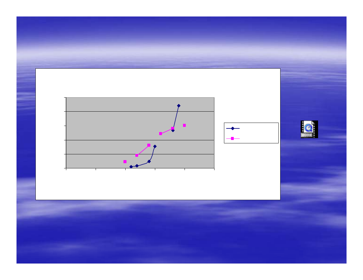
Performance Curves & Video
Performance Curves & Video
Power Curves - 2 S-Rotors
0
2
4
6
8
10
0
5
10
15
20
25
Vehicle Speed (mph)
Wa
tt
s
Plastic/Steel
Steel/Wood
Best.mov

Conclusions and Costs
Conclusions and Costs
Material costs for either Plastic/Steel or
Material costs for either Plastic/Steel or
Steel/Wood Rotor range from $150 to $250
Steel/Wood Rotor range from $150 to $250
U.S. Dollars
U.S. Dollars
Materials and tools are readily available
Materials and tools are readily available
Power ranges from 1 to 10 watts depending
Power ranges from 1 to 10 watts depending
on wind speed
on wind speed
Wind speeds between 10 to 20 mph needed
Wind speeds between 10 to 20 mph needed
Document Outline
- Building a Home-ScaleVertical Axis Wind Turbine
- OBJECTIVES
- Two Design Types
- Two S-Rotor Designs
- Materials-Plastic/Steel Rotor
- Materials-Plastic/Steel Rotor (cont.)
- Tools Needed
- Needed Skills and Tips
- Rotor Instructions: Plastic/Steel-Rotor
- Rotor Instructions (cont.)
- Rotor Instructions (cont.)
- Building Instructions (cont.)
- Frame Building Guidelines
- Frame Guidelines
- Performance Curves & Video
- Conclusions and Costs
Wyszukiwarka
Podobne podstrony:
1801 Design Analysis of Fixed Pitch Straight Bladed Vertical Axis Wind Turbines
(Wind) Novel Verticle Axis Wind Turbine {Paul Cooper & Oliver Kennedy}9
Separation Control Of High Angle Of Attack Airfoil For Vertical Axis Wind Turbines
Cranenbroeck Advanced Surveying Control Services for Building the Vertical Cities
Building A Wind Machine
[US 2005] 6864611 Synchronous generator for service in wind power plants, as well as a wind power
My Homemade wind generator
[2006] Application of Magnetic Energy Recovery Switch (MERS) to Improve Output Power of Wind Turbine
Innovative Solutions In Power Electronics For Variable Speed Wind Turbines
Home Power Magazine Betting the Farm Wind Electricity Pays Off
(WinD Power) Dynamic Modeling of Ge 1 5 And 3 6 Wind Turbine Generator {}[2003}
Foresight analysis of wind power in Turkey
(eolica) II PRINCIPLES OF A WIND POWER TURBINE?HAVIOUR(1)
[EP 2003] 1381775 WIND TURBINE POWER MODULE MOUNTED ON THE TOWER FOUNDATION
[PhD 2003] Wind Power Modelling and Impact on Power System Dynamics
Building A Wind Machine
więcej podobnych podstron