
Copyright 1999–2003 – Ohm Force
Page 1/45
The Ohm Force Experience User Manual
V 1.0
Date
2003.06.12
Ref -
The Ohm Force
Experience
Creative plug-in pack
User manual version 1.0 – 2003.06.12
This manual is copyright © Ohm Force 1999–2003. All rights reserved. No part may be
reproduced without written permission. VST technology by Steinberg Media Technologies AG.
All trademarks acknowledged.

Copyright 1999–2003 – Ohm Force
Page 2/45
The Ohm Force Experience User Manual
V 1.0
Date
2003.06.12
Ref -
– T
ABLE
O
F
C
ONTENT
–
1.
GETTING STARTED .............................................................................................................................................. 4
1.1
F
EATURES AND REQUIREMENTS
........................................................................................................................... 4
1.2
I
NSTALLING
......................................................................................................................................................... 5
1.2.1
Experience Pack CD-ROM ......................................................................................................................... 5
1.2.2
On-line download........................................................................................................................................ 5
1.3
F
IRST CONTACT
................................................................................................................................................... 5
1.4
R
EGISTRATION
..................................................................................................................................................... 6
2.
COMMON FEATURES........................................................................................................................................... 7
2.1
P
RESET PANEL
..................................................................................................................................................... 7
2.1.1
Presets / Memorize...................................................................................................................................... 7
2.1.2
Transition time ............................................................................................................................................ 7
2.1.3
Load / Save Bank ........................................................................................................................................ 7
2.2
U
SING KNOBS AND FADERS
.................................................................................................................................. 7
2.2.1
Direct action ............................................................................................................................................... 8
2.2.2
Side-clicks ................................................................................................................................................... 8
2.2.3
Linked buttons............................................................................................................................................. 8
2.3
P
ARAMETER INFORMATION AND MODULATION
.................................................................................................... 9
2.3.1
Parameters .................................................................................................................................................. 9
2.3.2
Tempo control ............................................................................................................................................. 9
2.3.3
LFO ............................................................................................................................................................. 9
2.3.4
Automation................................................................................................................................................ 10
2.3.4.1
Support.................................................................................................................................................. 10
2.3.4.2
VST limitations ..................................................................................................................................... 11
2.4
MIDI
SUPPORT
.................................................................................................................................................. 11
2.4.1
Selecting MIDI ports................................................................................................................................. 12
2.4.2
Binding parameters to MIDI controls....................................................................................................... 12
2.4.3
Saving and restoring the MIDI configuration........................................................................................... 12
2.4.4
About Control Change messages .............................................................................................................. 13
2.4.5
Other MIDI features.................................................................................................................................. 13
2.5
S
TAND
-
ALONE VERSIONS
................................................................................................................................... 13
2.5.1
Setup.......................................................................................................................................................... 13
2.5.2
Loading sound files ................................................................................................................................... 14
2.5.3
Playback toolbar....................................................................................................................................... 14
2.5.4
Volume control.......................................................................................................................................... 15
3.
OHMBOYZ ............................................................................................................................................................. 16
3.1
F
UNCTIONALITY
................................................................................................................................................ 16
3.1.1
Predelays................................................................................................................................................... 17
3.1.2
Delay lines ................................................................................................................................................ 18
3.2
U
SER INTERFACE
............................................................................................................................................... 19
3.2.1
Predelays................................................................................................................................................... 19
3.2.1.1
Tap description...................................................................................................................................... 19
3.2.1.2
Other controls........................................................................................................................................ 20
3.2.2
Delay lines ................................................................................................................................................ 20
3.2.2.1
Delay and mix ....................................................................................................................................... 20
3.2.2.2
Resonant filter ....................................................................................................................................... 21
RF .........................................................................................................................................................................21
3.2.2.3
Distortion .............................................................................................................................................. 22
3.2.2.4
High-shelf filter..................................................................................................................................... 22
3.2.2.5
Miscellaneous........................................................................................................................................ 22
3.3
MIDI
FACTORY SETTINGS
.................................................................................................................................. 23
3.3.1
Generic parameters................................................................................................................................... 23
3.3.2
Predelays................................................................................................................................................... 23
3.3.3
Delay lines ................................................................................................................................................ 24
Copyright 1999–2003 – Ohm Force
Page 3/45
The Ohm Force Experience User Manual
V 1.0
Date
2003.06.12
Ref -
3.3.4
LFO phases ............................................................................................................................................... 25
4.
PREDATOHM ........................................................................................................................................................ 26
4.1
F
UNCTIONALITY
................................................................................................................................................ 26
4.2
B
ANDS
............................................................................................................................................................... 26
4.2.1
Splitting ..................................................................................................................................................... 26
4.2.2
Band processing........................................................................................................................................ 27
4.2.2.1
Dynamics .............................................................................................................................................. 27
4.2.2.2
Distortion .............................................................................................................................................. 28
4.2.2.3
Mix........................................................................................................................................................ 28
4.3
E
ND OF THE CHAIN
............................................................................................................................................. 28
4.3.1
Tone .......................................................................................................................................................... 28
4.3.2
Feedback ................................................................................................................................................... 29
4.3.3
Stereo ........................................................................................................................................................ 29
4.3.4
Master section ........................................................................................................................................... 30
4.4
MIDI
FACTORY SETTINGS
.................................................................................................................................. 30
4.4.1
Generic parameters................................................................................................................................... 30
4.4.2
Band parameters ....................................................................................................................................... 30
5.
HEMATOHM ......................................................................................................................................................... 31
5.1
F
UNCTIONALITY
................................................................................................................................................ 31
5.1.1
Architecture............................................................................................................................................... 31
5.1.2
A frequency shifter? .................................................................................................................................. 31
5.1.3
Frequency shifter typical usage ................................................................................................................ 33
5.2
E
FFECT
.............................................................................................................................................................. 33
5.3
M
ODULATION
.................................................................................................................................................... 33
5.3.1
LFO ........................................................................................................................................................... 33
5.3.2
Envelope follower ..................................................................................................................................... 34
5.4
D
ELAY
............................................................................................................................................................... 34
5.5
MIDI
FACTORY SETTINGS
.................................................................................................................................. 34
6.
MOBILOHM........................................................................................................................................................... 36
6.1
F
UNCTIONALITY
................................................................................................................................................ 36
6.1.1
What is a phaser ?..................................................................................................................................... 36
6.1.2
Architecture............................................................................................................................................... 36
6.1.3
Cell description ......................................................................................................................................... 37
6.2
U
SING
M
OBILOHM
............................................................................................................................................. 38
6.2.1
Master volume........................................................................................................................................... 38
6.2.2
Tone .......................................................................................................................................................... 38
6.2.3
Cells .......................................................................................................................................................... 38
6.2.3.1
Oscillator............................................................................................................................................... 38
6.2.3.2
Feedback ............................................................................................................................................... 39
6.2.3.3
Filter...................................................................................................................................................... 39
6.2.3.4
Mix........................................................................................................................................................ 40
6.3
MIDI
FACTORY SETTINGS
.................................................................................................................................. 40
6.3.1
Generic parameters................................................................................................................................... 40
6.3.2
Cell parameters......................................................................................................................................... 40
6.3.3
LFO phases ............................................................................................................................................... 41
7.
FROHMAGE .......................................................................................................................................................... 42
7.1
F
UNCTIONALITY
................................................................................................................................................ 42
7.2
C
ONTROLS
......................................................................................................................................................... 42
7.2.1
Band control.............................................................................................................................................. 42
7.2.2
Central panel ............................................................................................................................................ 43
7.2.3
Distortion .................................................................................................................................................. 43
7.3
MIDI
FACTORY SETTINGS
.................................................................................................................................. 44
8.
CREDITS AND THANKS ..................................................................................................................................... 45

Copyright 1999–2003 – Ohm Force
Page 4/45
The Ohm Force Experience User Manual
V 1.0
Date
2003.06.12
Ref -
1. Getting started
Thank you for purchasing The Ohm Force Experience plug-in pack. This manual is divided
into three sections:
Getting Started: explains how to install the Experience plug-ins and get them working;
Common features: rounds up the common features you will see on every effects in the
pack;
Using the effects: shows you how to operate each plug-in.
1.1 Features and requirements
The Ohm Force Experience is a pack of five high-quality audio effects, including:
•
OhmBoyz, a multi-tap delay
•
Predatohm, the award-winning multi-band compression and distortion
•
Hematohm, a frequency shifter
•
Mobliohm, a multi-phaser
•
Frohmage, a low-pass filter.
All of them are available in two interfaces, the “Classic Skin” and the “Funky Skin”.
They work as stand-alone programs, or as plug-ins for various platforms. The requirements
given below may vary depending on the latest program versions. See the latest release notes
in the file readme.txt on the CD–ROM.
You will need at least 64 MB of RAM, 25 MB on your hard-drive, a Pentium II-compatible PC
or a G4-compatible CPU on Apple Macintosh.
•
MacOS Classic
Requires OS 9.x and CarbonLib 1.5 or higher. Find out how to update on the Apple website:
http://www.apple.com/support/
. The plug-ins are available for the VST, MAS and RTAS
platforms.
•
MacOS X
Requires OS 10.1 or higher. The plug-ins are available for the VST and AudioUnits
platforms.
•
Windows
Requires Windows 98, 98 SE, ME, 2000 or XP. The plug-ins are available for the VST,
DirectX and Winamp 2 platforms.
Copyright 1999–2003 – Ohm Force
Page 5/45
The Ohm Force Experience User Manual
V 1.0
Date
2003.06.12
Ref -
1.2 Installing
Depending on how you got the product(s) (Experience Pack CD-ROM or web download),
there are several ways to install the plug-ins.
1.2.1 Experience Pack CD-ROM
Insert the CD-ROM into your computer. If the installer does not pop up automatically, open
the CD folder and double-click on the installer icon. Then follow the instructions.
1.2.2 On-line download
Each version of each plugin has its own installation file. This, inevitably, means that there
are a large number of files to choose. To make finding the one relevant to you as easy as
possible, we have labeled them in the following way:
PluginNameVersion_Platform_license
For example, OhmBoyz134_vst2win_pro.exe is the installer for the “OhmBoyz v1.34 for VST
on the Windows platform, RTAS ProPack license”.
Only run the installers for the plug-in and version you need. There is no obligation to install
all of them. Follow the instructions given by the installers as they may vary from platform to
platform. Each plug-in has a unique serial number needed for the installation. Check the label
on your manual cover, there should be four groupings of User Id / Serial Number. When
prompted by the installer, enter these details exactly as they appear on the label.
Warning: Serial numbers are checked only when the plug-in is actually used. If you
mistyped the codes, a dialog box will warn you when you try to run the plug-in or during the
host program startup, not during the install process. To correct the serial number, you have to
quit the host application and reinstall the plug-in to the same location as previously. If you
decide to change the installation location, uninstall the plug-in first. It is prudent to
systematically uninstall plug-ins in the event of a registration code error.
Note: The stand-alone versions do not require a registration code to install.
1.3 First contact
Open a plug-in from the pack and feed it some sound. The MacOS Classic users should
ensure that there is enough memory reserved for the application.
A good way to start a feel for the units is to try the factory presets. On each plug-in you will
find a frame with eight numbered buttons in it. Click on these buttons to activate the eight
factory presets.
Copyright 1999–2003 – Ohm Force
Page 6/45
The Ohm Force Experience User Manual
V 1.0
Date
2003.06.12
Ref -
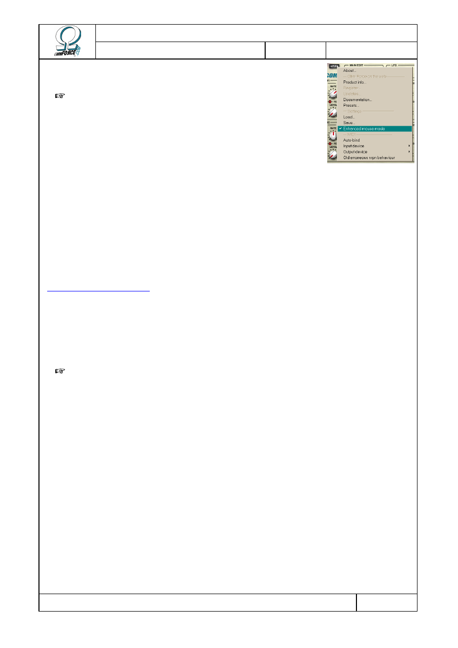
Turn the knobs by clicking on them and dragging the mouse
vertically.
Note: If your mouse suddenly goes mad, stay calm and locate
the S
ETUP
button. Click on it to open the menu and unselect
E
NHANCED
M
OUSE
M
ODE
. This may happen with some mice, graphic
tablets or trackball devices.
1.4 Registration
In order to get the latest updates and support directly from the Ohm Force website, you can
register your plug-ins on-line. Experience Pack users: as you probably noticed during the
installation, the “User name” field is rather impersonal and identifies you with a number
displayed on the plug-in panel. If you register your plug-in, another code will be sent to you
that will label the plug-in to your own name.
To register, click on the S
ETUP
menu and select R
EGISTER
. Your computer should be
connected to the Internet. The Register option will open a browser on the Ohm Force web site
(
http://www.ohmforce.com
). You will also need to have an account on this web site; if you still
do not have one, you will be given the opportunity to create one. Follow the instructions on the
web page.
If the computer on which the plug-ins are installed is not connected to the Internet, you can
still register using another computer that is. Log in using your Ohm Force account. Click on
H
OME
then M
Y
O
HM
F
ORCE
P
RODUCTS
and follow the instructions in the Registration
Management section.
Important: If you choose to get a personalized code, you will have to reinstall the plug-
ins, as the old registration code will become obsolete.
Copyright 1999–2003 – Ohm Force
Page 7/45
The Ohm Force Experience User Manual
V 1.0
Date
2003.06.12
Ref -
2. Common features
Ohm Force's plug-ins all share a lot of important features. They might not look alike,
because of variations in the graphic design, but they have the same basic functionalities. Let's
review them.
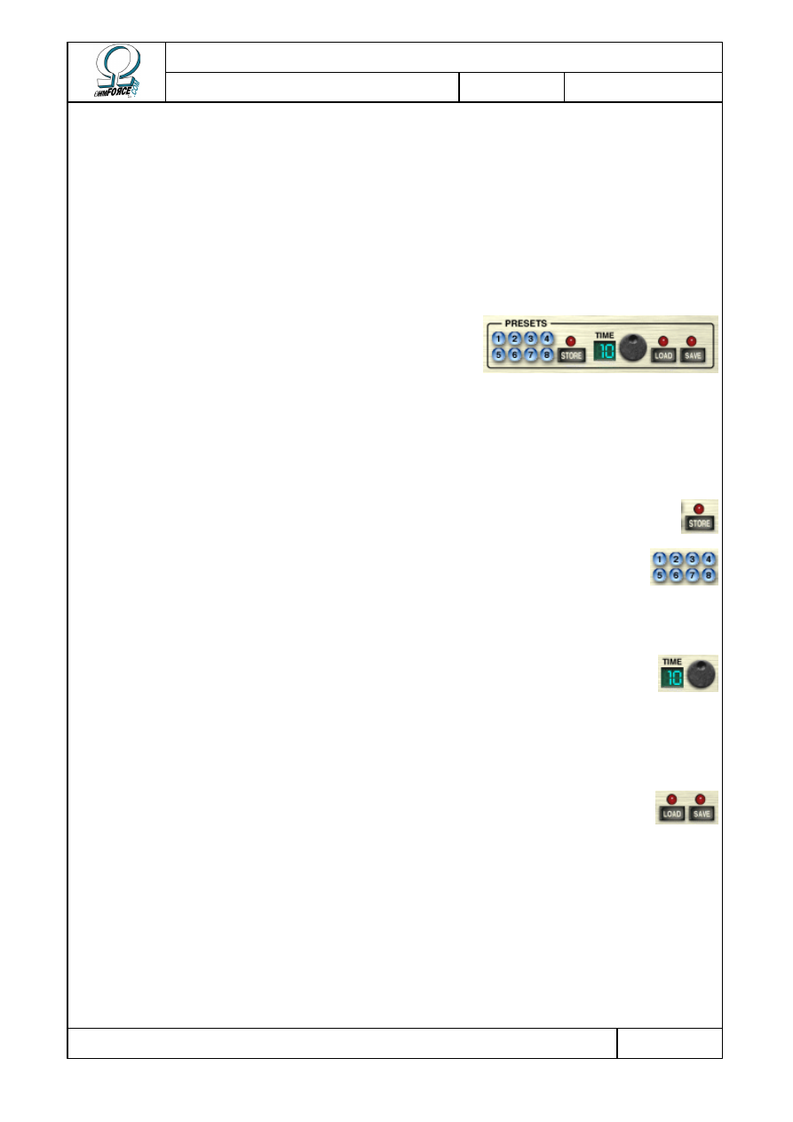
2.1 Preset panel
This bank of eight buttons enables you to memorize
your settings. Banks can then be saved onto your hard
disk. They are multi-platform, so you can load your
presets in any sequencer, or even on another computer.
You can also adjust the speed at which the knobs and sliders move from the current setting
to the new one.
2.1.1 Presets / Memorize
To memorize the current settings, click once on the M (or S
TORE
) button; it
will light up. Then click the preset button in which you wish to store the settings.
To apply a preset, make sure the M light is off. To turn it off, click the M
button once. Then click on the preset button you want to activate.
2.1.2 Transition time
This potentiometer enables you to vary the time the plug-in will take to morph
between two presets. The time, measured in seconds, is displayed beside it. By
default, the duration is set to one second. Set it to 0 if you want the preset
applied instantaneously.
2.1.3 Load / Save Bank
Use these two buttons to save and load your preset banks to and from the
hard disk. A bank contains the eight settings stored in the preset buttons.
Loading a bank will not modify the current settings until you select a number.
There are many presets bundled with your plug-ins. If you're trying to achieve a
particular sound, you can start with the preset closest to the idea you have in
mind and then tweak the settings to get the desired result.
2.2 Using knobs and faders
All knobs and faders work the same way. There are two modes: direct action and slide-
clicks.
Copyright 1999–2003 – Ohm Force
Page 8/45
The Ohm Force Experience User Manual
V 1.0
Date
2003.06.12
Ref -
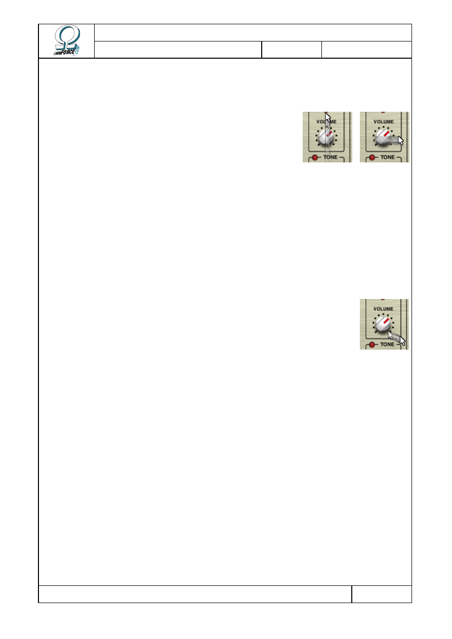
2.2.1 Direct action
You can move a knob by clicking on it (click on the slider part of a fader) and then keeping
the button pressed while moving the mouse up or down.
Actually, each button has a preferred direction for the mouse
movement: vertical for knobs and according to orientation for
the faders. If you move the mouse in the preferred direction, the
knob will turn quickly. However, if you move your mouse in the
perpendicular direction – i.e. horizontally for knobs, the
movement will be slow and very accurate.
Some potentiometers have notches which lock to certain values. It is possible, however, to
set the potentiometer position between two notches by moving the mouse in the perpendicular
direction, as mentioned above.
2.2.2 Side-clicks
The button is divided into two zones on which you can click to turn the button to the right or
to the left. For faders, the two zones are on either side of the slider. For knobs, they are
positioned at 4:30 and 7:30 on dial. The buttons will move slowly if you click and hold on these
zones without moving the mouse. This enables you to make very small adjustments to settings
with ease.
Flying knobs. If you click on this zone then move the mouse without
releasing it, the button will move automatically, and keep moving even after
you have released it. The further you move the mouse, the faster the button
will move. To stop the movement, just click on the button again. This is
especially useful during live sessions, as you can have many parameters
shifting at the same time without having to use the preset morphing feature.
2.2.3 Linked buttons
On most of the plug-ins (all except the Hematohm and the Frohmage), some knobs can be
linked, as they control similar parameters. For instance the parameters of the two OhmBoyz’
delay lines can be linked. This means that you can alter a parameter in both Line 1 and Line 2
at the same time – with a single click.
To do so, you have to click on the parameter with the right mouse button (click while
holding the [C
ONTROL
] key on Macintosh systems). The knobs in both channels will now move
in unison.
If you hold the [S
HIFT
] key and click on the right mouse button, both knobs move at the
same time but keep their own original gap. For instance, if the original value of the first knob
is 10 % and the original value of the second knob is 50 %, when you increase the value of the
first knob to 30 %, you will increase the value of the second button up to 70 % at the same
time.
You can undo the movement of the slave knobs by performing a right mouse click while
holding the [C
ONTROL
] key (the [C
OMMAND
] key on Macintosh).
Copyright 1999–2003 – Ohm Force
Page 9/45
The Ohm Force Experience User Manual
V 1.0
Date
2003.06.12
Ref -
2.3 Parameter information and modulation
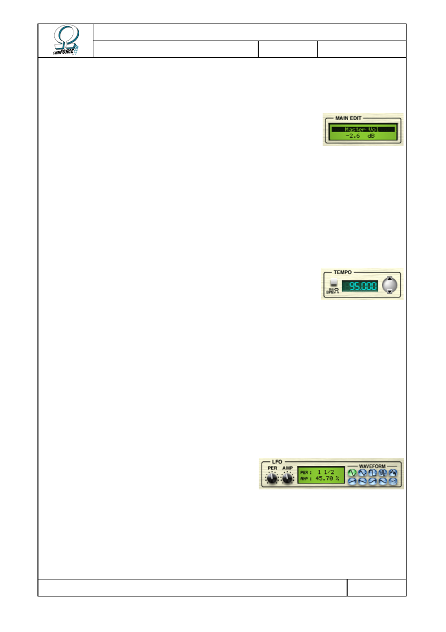
2.3.1 Parameters
This contextual display shows details of the selected parameter, the
one outlined in color. It would be horrifically complex if all the numeric
parameter values were displayed on the interface at once.
•
N
AME
Name of the selected parameter.
•
V
ALUE
This is the parameter value expressed in the selected unit (BPM or Hz). You can edit this
value by clicking on it. Press [R
ETURN
] to validate your change or [E
SCAPE
] to cancel it.
2.3.2 Tempo control
Because many plug-in applications are related to music and,
therefore, to rhythm, it is necessary to be able to synchronize with the
tempo of a piece.
Some host programs can automatically synchronize the plug-in’s internal tempo with their
own tempo. Alternatively, you can change the tempo by clicking on the buttons to the right of
the numeric display. You can also type into the numeric display itself.
The tempo feature is available on every plug-in except the Frohmage and Predatohm, since
these have no time-sensitive parameters.
2.3.3 LFO
Most of the Ohm Force plugins come with a modulation unit: the LFO, standing for Low
Frequency Oscillator. This is an oscillator producing a signal usually below the audio frequency
range. This signal additively modulates the parameter with which it is associated, causing it to
oscillate around a central value. This is useful for creating vibratos, tremolos or panoramic
rotations, along with more unusual effects.
Like the Parameter display, the LFO display is
activated when a parameter that has an associated
LFO is selected.
•
P
ERIOD
This is the time taken for one LFO oscillation (the length of the wave). LFOs are
synchronized to the tempo value to keep them in time with the music.
•
A
MPLITUDE
Copyright 1999–2003 – Ohm Force
Page 10/45
The Ohm Force Experience User Manual
V 1.0
Date
2003.06.12
Ref -
This is the amplitude of the oscillations (the height of the wave). A 0% setting means that
the LFO will not affect the sound.
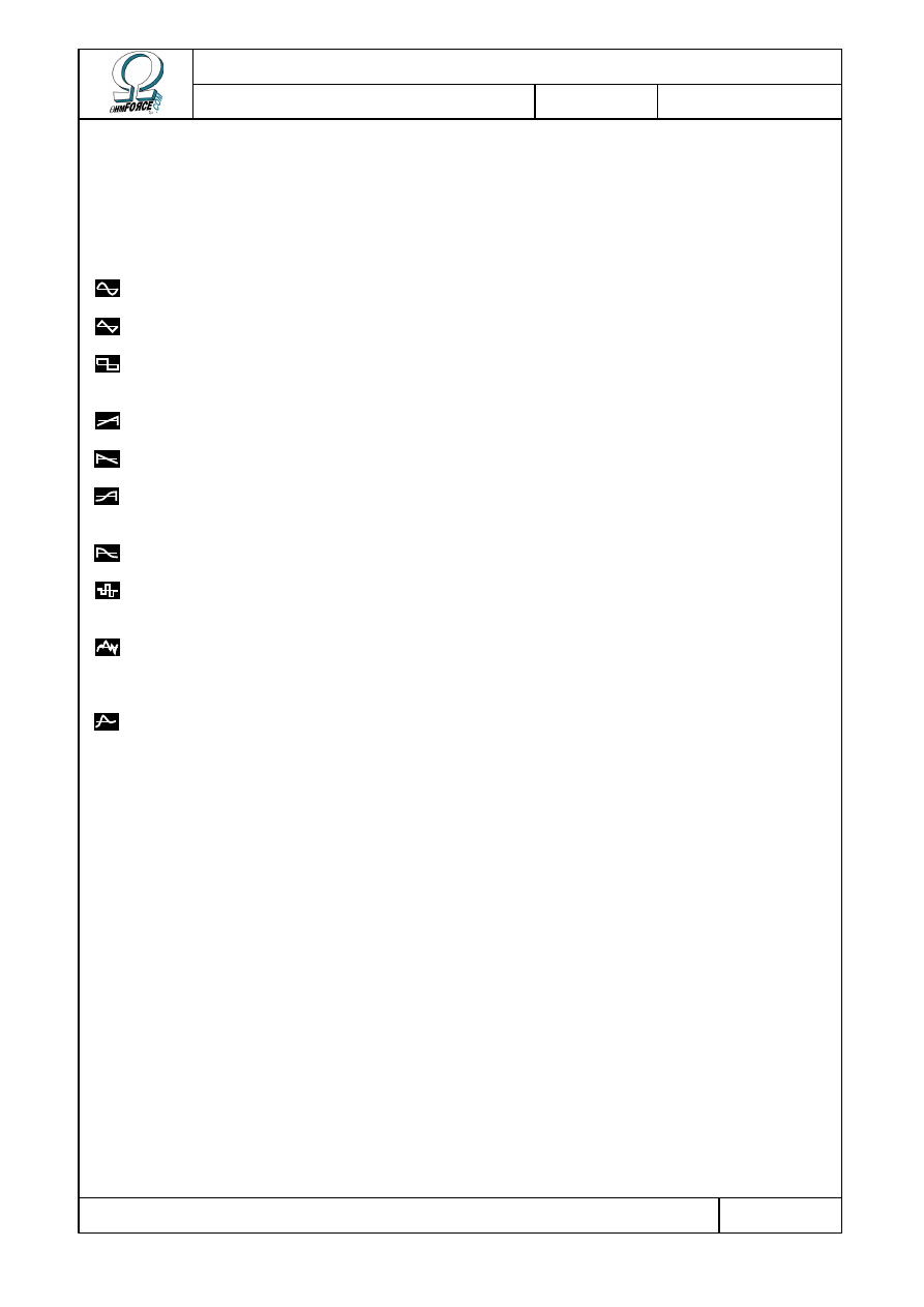
•
W
AVEFORM
This parameter defines the shape of the oscillations. Seven of the shapes are classic, the
three others are random oscillators.
S
INE
It is the default waveform. LFO sweeps smoothly back and forth.
T
RIANGLE
LFO travels linearly between two extreme points.
S
QUARE
LFO stays for one half-period at the maximum point, then for the other
half-period at the minimum point.
R
AMP UP
Goes linearly from the minimum point to the maximum one.
R
AMP DOWN
Like Ramp up, but in the other direction.
C
OS UP
A bit like Ramp up, but the LFO goes and arrives more gently at the
extreme points (a kind of shelf).
C
OS DOWN
Like Cos up, but in the other direction.
R
ANDOM
STEPS
When a period starts, the LFO generates random values which it keeps
constant until the end of that period.
B
ROWN
NOISE
LFO value changes randomly, combining wide, slow moves with small,
fast oscillations. With a very long period, this kind of LFO is perfect for
giving a parameter a natural, nervous, random variation.
R
ED NOISE
Somewhat like Brown Noise, but fast variations are damped, generating
even smoother random walks.
2.3.4 Automation
2.3.4.1
Support
Every parameter, including modulation settings (LFOs, etc.) is potentially automatable on
the RTAS, MAS, VST and AudioUnit platforms. However depending on your host’s capabilities,
you may be restricted to only 16 fixed parameters, or even have no automation capability at
all. Check the host’s reference manual to find out how to automate a parameter.
Digital Performer and ProTools display on the plug-in interface itself which parameters are
currently automated. A green triangle on a knob indicates that the automation is playing, and
a red disc shows automation being recorded.
The DirectX version does not support automation and DXi features yet, please use MIDI
automation instead.
Copyright 1999–2003 – Ohm Force
Page 11/45
The Ohm Force Experience User Manual
V 1.0
Date
2003.06.12
Ref -
2.3.4.2
VST limitations
Some host programs like Emagic Logic Audio or earlier versions of Steinberg Cubase VST
have several limitations regarding VST plug-in automation. They can handle only a few
parameters, which is unfortunate as some Ohm Force plug-ins have hundreds. As a
consequence, some important parameters cannot be automated. It is possible to get around
this by using MIDI commands, but this is not always the most convenient solution.
To alleviate this problem, we give you the option of changing the order in which the VST
parameters are presented to the host. We should warn you that this section is rather technical.
Proceed by selecting S
ETTINGS
/ L
OAD
in the S
ETUP
button menu. Locate the file
easy_vst_automation.cfg.txt
in your effect's installation folder and open it. This will move
the most important parameters to the top of the VST list so that they can be automated.
If happy with the provided configuration file, you can make your own. First, save a
configuration using S
ETTINGS
/ S
AVE
(eg. my_settings.cfg.txt) load it into a text editor,
along with easy_vst_automation.cfg.txt so you can take a look for reference. You can see that
a configuration file is made of "keys". They have a name and a content, which can be made of
other keys, a recursive structure known as a tree in scientific circles. Key name and content
are separated by an equals sign (=), and complex key contents are enclosed by brackets.
The provided configuration file should be a lot smaller than your homemade one. This is
because it is a partial configuration, whereas yours is a complete one. Suppress some
irrelevant subkeys (the midi section, for example) in order to make the two files look more
alike. Yours will inevitably remain longer.
Let's focus on the parameter_reorder_map key. You'll see several parameter names as the
file you have just saved contains all potential plug-in parameters. Move the parameters you
want to automate to the top of the list. You can specify a particular order for the other
parameters if you want to, or you can simply suppress them. This does not mean that they will
not appear any more, or become unavailable for automation. When loading the configuration
file, the plug-in will automatically find the best mapping for the suppressed parameters. Once
you have finished sorting the parameters, save your work and load your configuration file into
the plug-in.
Important: If you created settings before applying the mapping file, you should save
them into an internal preset – as described in the Preset section of this manual. You should not
use the VST host's presets anymore because they will be completely reordered after the
change. Instead, apply your saved internal ohm preset to restore your sound. Fortunately, new
presets you make after the change can be stored in VST format and reloaded.
2.4 MIDI support
You can also use MIDI commands to control the plug-in parameters. MIDI can even replace
automation, because not only can the plug-ins receive MIDI commands, they can also emit
them.
The effects are in “Omni” mode, meaning they can receive MIDI commands from any
channel. However, all commands are sent via Channel 1. Commands can be regular CC
(Continuous Controllers), or RPN and NRPN (Non-Registered Parameter Numbers). The
decision as to whether to use CC or NRPN will depend upon the capabilities of your midi device.
CC is commonly used by hardware devices, but NRPN has a higher resolution.
Copyright 1999–2003 – Ohm Force
Page 12/45
The Ohm Force Experience User Manual
V 1.0
Date
2003.06.12
Ref -
The factory MIDI settings use NRPN, but it is possible to change the mapping at any time.
The default mapping for each plug-in is listed in the respective section of this manual.
Note: MIDI support is disabled in the demo versions.
2.4.1 Selecting MIDI ports
Depending on your host, your MIDI devices and your system settings, you may have more
than one MIDI port available for MIDI input and output. It is possible to select which virtual
port you wish to use for receiving and sending MIDI events.
To choose the input port - the one from which MIDI data is received by the plug-in - click on
the S
ETUP
button, go to the MIDI / I
NPUT DEVICE
menu and select the one you want. Do the
same thing to select the output port, except, of course, you will need to click MIDI / O
UTPUT
DEVICE
. The selected MIDI port will be ticked in the menu. You can only use one input and one
output port at any one time.
If the connection fails, it is usually because the port you selected is already in use by
another application – most likely the host itself. In this case, check your host’s operating
manual to see if it is possible to free up the port.
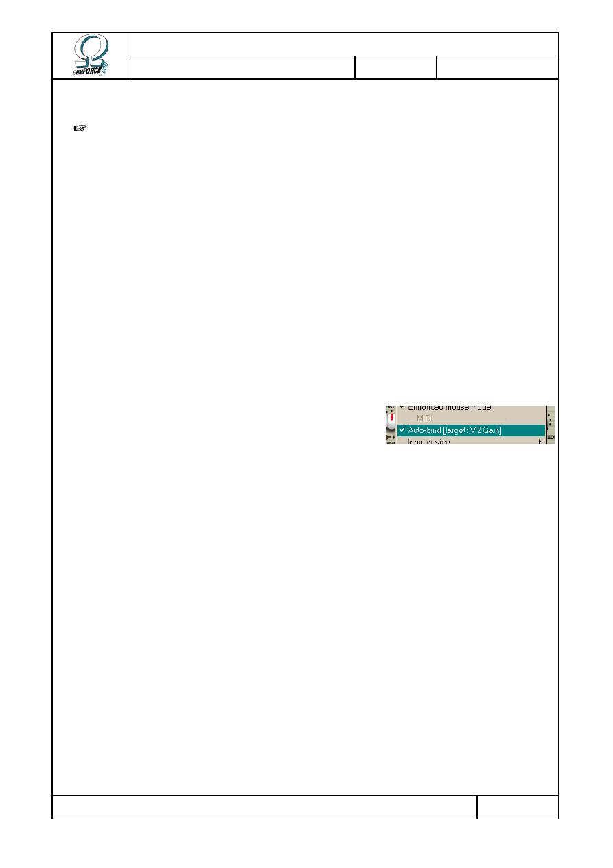
2.4.2 Binding parameters to MIDI controls
The easiest way to associate a parameter with a specific
MIDI controller knob, or any MIDI Control Change, is to
use the auto-bind feature. First, activate the auto-bind
mode by checking MIDI / A
UTO
-
BIND
in the S
ETUP
menu.
If you have already selected a parameter its name will be displayed in brackets in the
menu, like this: Autobind [target : Volume]. If not, click on the knob you want to bind to a
MIDI control change. Only the last one selected will be taken into account for binding.
Once you have chosen the parameter, send a MIDI event to the plug-in (for example, turn a
knob on your external MIDI controller). It can be a simple CC, an RPN or an NRPN command.
As soon as the event is received, the connection is created automatically, and the MIDI
command will remain associated with this parameter. Only one parameter can be bound to
each MIDI command, and visa versa.
If you want to bind more parameters, repeat the procedure: select another parameter, and
send another MIDI event. Do not forget to exit the auto-bind mode, by un-checking the
corresponding entry in the S
ETUP
menu, when you have finished.
2.4.3 Saving and restoring the MIDI configuration
If you have numerous parameters to bind each time you want to use the plug-in, you can
save the configuration for later use. Currently selected ports will also be saved.
To do so, select S
ETTINGS
/ S
AVE
in the S
ETUP
menu. You can restore the settings at any
time by selecting S
ETTINGS
/ L
OAD
.
Copyright 1999–2003 – Ohm Force
Page 13/45
The Ohm Force Experience User Manual
V 1.0
Date
2003.06.12
Ref -
Important: the MIDI configuration is not stored in presets, and therefore is not saved
with the host song. You will have to load the settings manually after having loaded a song on
your host application.
The true tech freaks among you will notice one can open the saved file in a text editor and
tweak the configuration from there. It is also possible to build “partial” configurations by only
keeping a couple of the “keys”. The content syntax is quite simple, but will not be covered in
this manual.
2.4.4 About Control Change messages
Although you can assign most of the CC numbers to plug-in parameters, there are things to
consider:
•
You cannot use certain CC numbers like Data Entry (6 and 38), Data Button Increment
(96), Data Button Decrement (97), nor you can use RPN and NRPN Parameters 98, 99,
100 and 101, because they are used for RPN and NRPN coding.
•
It is possible, but not advisable, to use the fine tuned section at the lower end of the
controller range (32 to 63). This will work, but if plug-in parameters are assigned to
coarse parts of the low controller range (0 to 31), the plug-in will also output the fine
commands, resulting in possible interference. For example, if you assigned Knob A to
CC 20 and Knob B to CC 52 (= 20 + 32), twisting Knob B would output CC 52
messages, whereas twisting Knob A would output both CC 20 and 52! Trying to record
automation in this manner could open the door to a whole world of pain.
2.4.5 Other MIDI features
•
O
LD ERRONEOUS
NRPN
BEHAVIOUR
This option is checked by default, and exists for historical reasons. Our plug-ins used to
interpret RPN and NRPN controls erroneously. As a consequence, automation recorded using
old versions cannot be interpreted by the recent versions unless this option is checked. You are
advised to uncheck this option if you are a new Ohm Force user.
2.5 Stand-alone versions
Each plug-in also exists as a stand-alone application, capable of playing and looping a sound
file, or processing soundcard input.
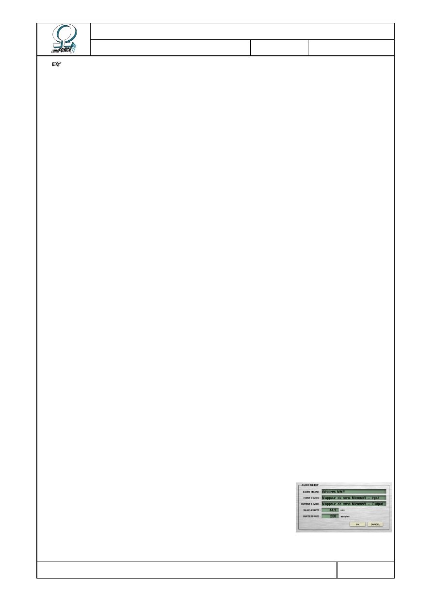
2.5.1 Setup
The first time you run a stand-alone version of an effect, you
will be asked to setup your sound card. You can change it at any
time by clicking on M
ENU
/ A
UDIO SETUP
…. The dialog has several
fields.
•
A
UDIO
E
NGINE
Copyright 1999–2003 – Ohm Force
Page 14/45
The Ohm Force Experience User Manual
V 1.0
Date
2003.06.12
Ref -
Here you can select the driver category used to produce and capture audio. Use ASIO only if
you have specific ASIO drivers installed on your computer. Windows user may prefer the
DirectX drivers over MME. Changing the audio engine will automatically stop the sound input
and output, even if you have not yet pressed the O
K
button.
•
I
NPUT
D
EVICE
, O
UTPUT
D
EVICE
Here you can select the devices for sound input and output. To make the program work at
all you will have to specify an output device.
•
S
AMPLE
R
ATE
Choose the sample rate. Default is 44.1 kHz, but you can set it higher if your soundcard
supports more.
•
B
UFFER
S
IZE
This is the buffer size, in samples. Buffer size affects latency, which is the unavoidable delay
between user/sound input, and what you actually hear. You will need a small buffer size to
achieve a low latency. However, small buffers tend to increase CPU load. Selecting 256
samples seems to be a good compromise in most cases.
2.5.2 Loading sound files
When no sound file is loaded, the effect processes the input of the sound card. To load a
sample, click on M
ENU
/ L
OAD
S
AMPLE
… and select a file from your disk. The sample will be
integrally loaded in RAM before processing, so be careful not to pick up a multi-gigabyte file!
On MacOS 9, if you encounter a problem as soon as you try to load a sample, there are
chances that you did not allocate enough memory for your application. Quit, select the effect
icon, press C
OMMAND
–I, choose the M
EMORY
item and specify a bigger amount.
You can change the sound file by repeating the operation described above, or return back to
input processing by choosing C
LOSE
S
AMPLE
in the M
ENU
.
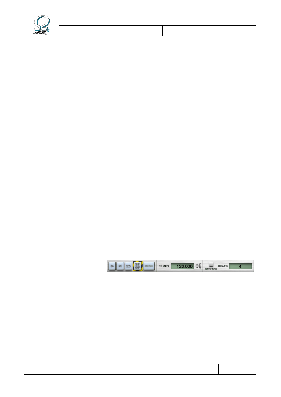
2.5.3 Playback toolbar
This controls playback.
•
P
LAY
– S
TOP
Push this button, when you have a sample loaded, to start playback. The button icon turns
into a square. Press it again to stop playback.
•
R
EWIND
Restarts the sample without interrupting playback.
•
L
OOP
Activates or deactivates the loop mode for the sample playback.
•
P
ANIC
Copyright 1999–2003 – Ohm Force
Page 15/45
The Ohm Force Experience User Manual
V 1.0
Date
2003.06.12
Ref -
Cuts out all sound. Useful when you've let things get a little out of hand and your resonant
filter is about to blast your speakers through the ceiling.
•
M
ENU
Click here to access the configuration menu.
•
T
EMPO
You can slave the plug-in tempo to the BPM (Beats Per Minute) value indicated in this box.
Use the arrow buttons to alter it, or enter the tempo manually by clicking on the box.
•
S
TRETCH
Stretch the sample playback to match the duration given by the tempo and the number of
beats.
•
B
EATS
This field is taken into account only when the S
TRETCH
function is activated. It tells the
program how many beats there are in the sample loop, as it cannot calculate this itself. Of
course, this value will vary depending on the sample you have loaded, so you will have to
adjust it for each new file.
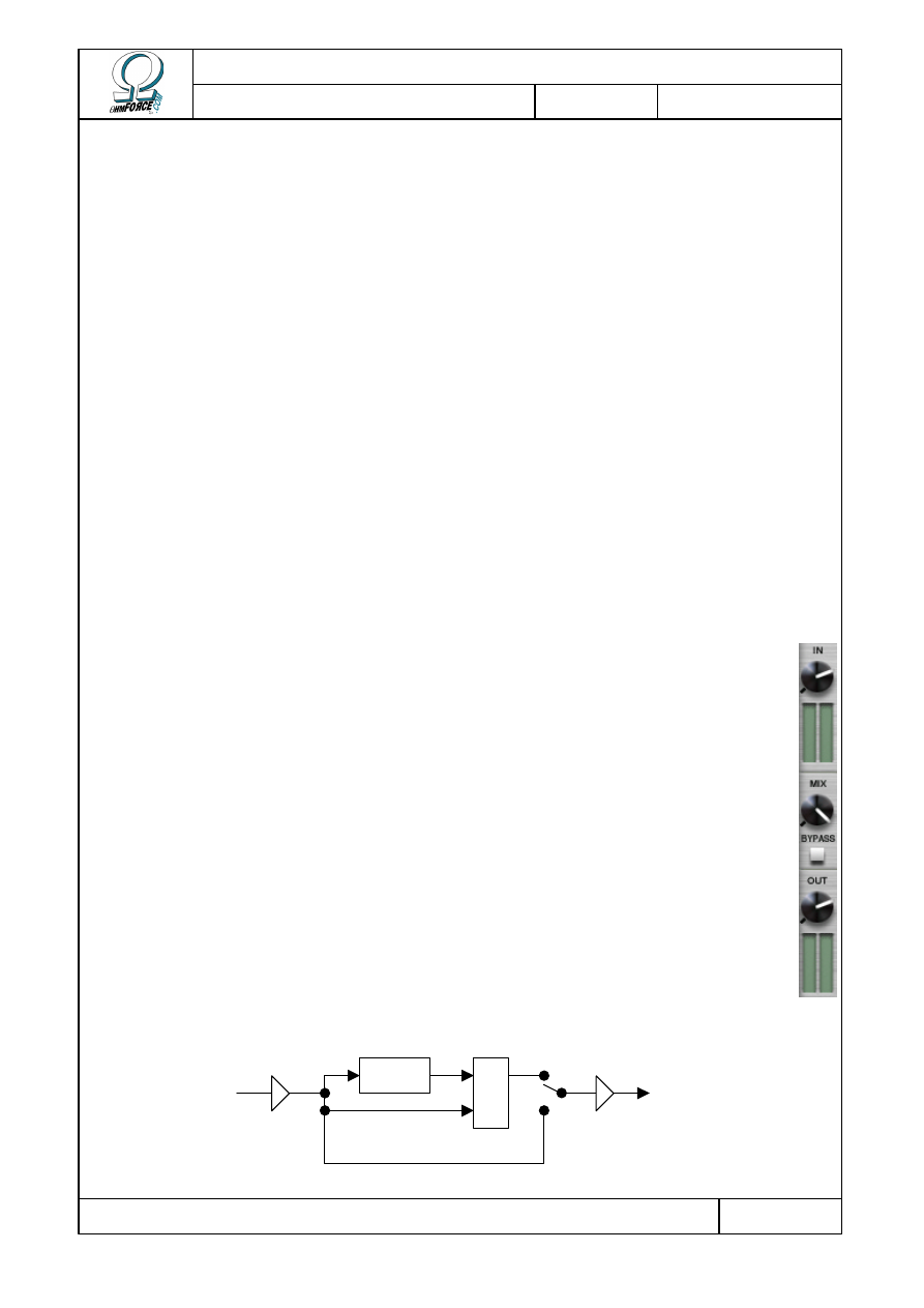
2.5.4 Volume control
•
I
N
Controls the level of sample playback or audio input. The vu-meter indicates the
volume after amplification.
•
O
UT
Controls the output volume of the plug-in. The vu-meter indicates the final volume
of the signal sent right to the output.
•
M
IX
Sets the balance of effect input (“Dry”) and output (“Wet”) sent to the sound card.
Turn the knob to the left for input only and to the right for output only.
•
B
YPASS
When activated, the effect is bypassed, meaning that the output is directly routed to
the output. Input and output volumes are still effective.
Effect
Mix
Output
volume
Input
volume
Bypass
Dry
Wet
Copyright 1999–2003 – Ohm Force
Page 16/45
The Ohm Force Experience User Manual
V 1.0
Date
2003.06.12
Ref -
3. OhmBoyz
3.1 Functionality
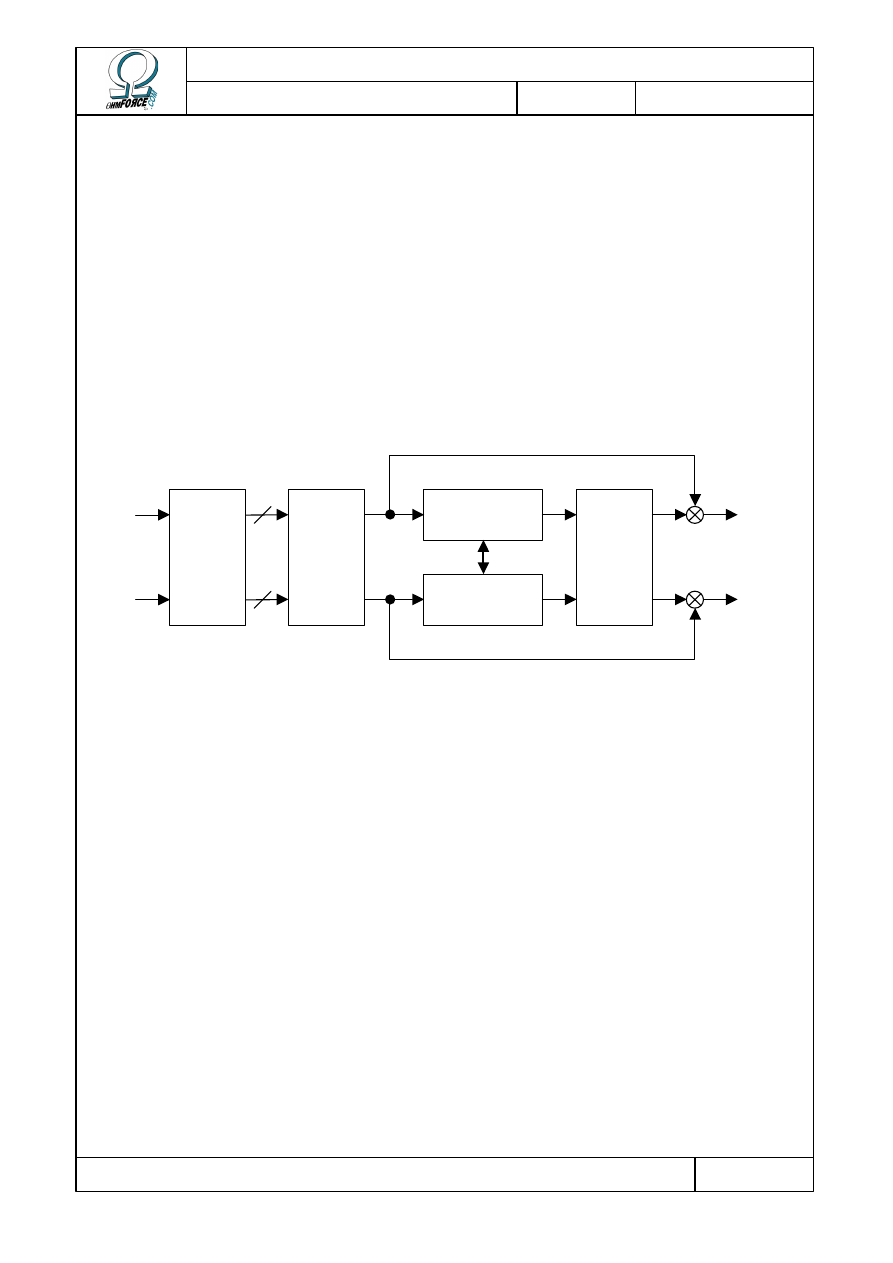
This section is somewhat technical, but it will help you to understand the OhmBoyz,
enabling you to get the results you want more rapidly. The OhmBoyz could be described as a
stereo delay, but that wouldn't do its capabilities justice. Essentially, it has two different
stages:
•
4 predelays, which can produce 4 one-hit repeats of the sound, shifted in time.
•
2 delay lines, each generating a decaying echo of the signal from the predelays.
Various effect parameters are connected to LFOs. These enable parameters to oscillate
around a central value. This feature can be used to create an “organic” sound that shifts
constantly.
Multi-tap
predelay
Delay line 1
Delay line 2
Pan
Pan
IN
Right
IN
Left
OUT
Right
OUT
Left
Copyright 1999–2003 – Ohm Force
Page 17/45
The Ohm Force Experience User Manual
V 1.0
Date
2003.06.12
Ref -
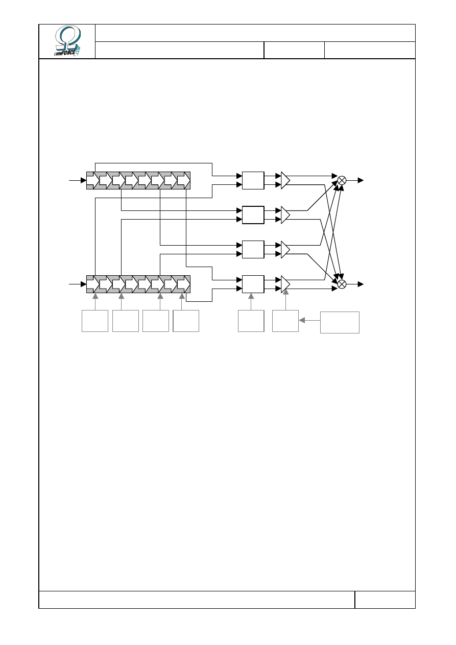
3.1.1 Predelays
This stage generates four one-hit delays. The time delay of each hit can be adjusted, as well
as the volume and stereo balance. When only one of the main delay lines is activated, the pan
knob has no effect. If you only want one tap, the 3 other tap volumes have to be set to 0.
Delay
time 3
Delay
time 4
Delay
time 2
Delay
time 1
Tap N
Pan
Tap N
Level
Sustained
loop
Pan
Pan
Pan
Pan
IN
Left
IN
Right
Delay 1
Delay 2
Pre-delay lines
Copyright 1999–2003 – Ohm Force
Page 18/45
The Ohm Force Experience User Manual
V 1.0
Date
2003.06.12
Ref -
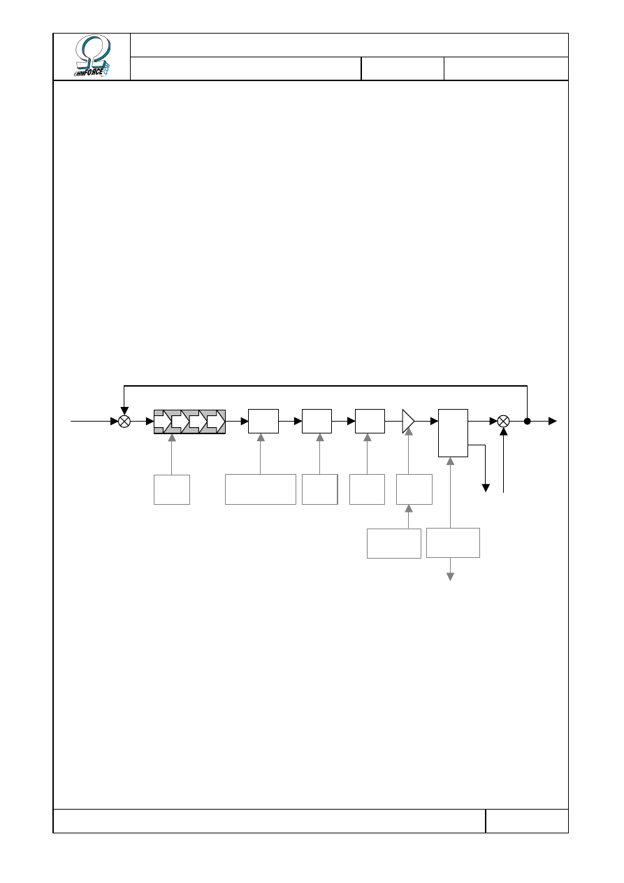
3.1.2 Delay lines
The most important part of the sound effect. The predelay stereo output, is sent to either
one or both of the delay lines, depending on the settings you have chosen. If you activate both
delay lines, the left output will go to the first one, and the right to the second.
Each one of these two delay lines has the basic parameters of a classic delay: delay time –
which defines the spacing of the echoes, and feedback amount – which defines the amount of
time it takes for the echoes to fade away.
We also added some other processing, such as filtering and distortion, as part of the delay
loop. Thus the signal is regularly reprocessed and the effect amplifies.
When using both lines of delay, it is possible to “cross” the feedback. In crossed mode, the
output signal of the first line is injected into the second line, and the output signal of the
second line is injected into the first line. Any degree between “straight” and “crossed” mode
can be obtained.
Finally, the output from the two lines can be balanced and mixed with the predelay output.
Feed-
back
Level /
Type
Feedback
separation
Cutoff /
Level
Type / Cutoff /
Reso / Q
Delay
time
Sustained
Loop
Predelay
Other delay
line
Filter
Disto
High
shelf
Pan
Mix
Delay line
Copyright 1999–2003 – Ohm Force
Page 19/45
The Ohm Force Experience User Manual
V 1.0
Date
2003.06.12
Ref -
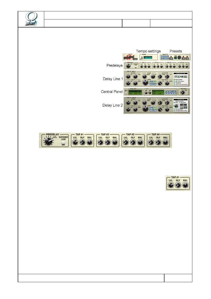
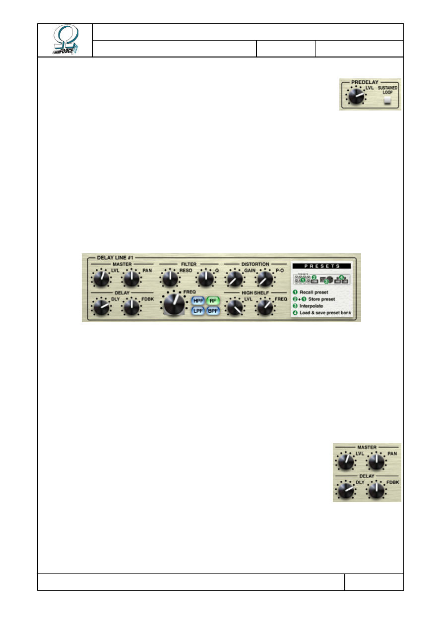
3.2 User interface
The user interface is divided into
several distinct parts :
•
Presets
•
Tempo setting
•
Predelays
•
The two delay lines
•
Central panel
Presets, tempo setting and central
panel are described in the Common
Feature chapter. We will discuss here
only the predelays and the delay lines.
3.2.1 Predelays
This panel allows you to control the predelay parameters. Each of the four groups of buttons
corresponds to a “tap”.
3.2.1.1
Tap description
•
D
ELAY
This is the delay time of each sound replica.
•
L
EVEL
This controls the volume of the tap. 0 dB is the volume of the original sound.
•
BAL
This is a panoramic potentiometer controlling:
•
The mix from the predelay outputs. It works like a standard stereo balance.
•
The input to the delay lines. When the two delay lines are activated, a pan set to the
left will direct the sound to the first line, and a pan set to the right will direct it to the
second line.
Copyright 1999–2003 – Ohm Force
Page 20/45
The Ohm Force Experience User Manual
V 1.0
Date
2003.06.12
Ref -
3.2.1.2
Other controls
•
P
REDELAY LEVEL
This only controls the mix of the taps in the final output signal. You can
control their volume separately. The normal volume is 0 dB.
•
S
USTAINED LOOP
When you click on this magic button, you will generate a sustain loop (infinite echo). A
sustain loop has the following characteristics:
•
Sound input is muted
•
Feedback of the two delay lines is set to 100%
Your settings are not lost, they are just bypassed. Click again to get the original sound
back.
3.2.2 Delay lines
Depending on the mode you have chosen, one or two delay lines will be displayed. They
have the same functions and each one can be divided as follows:
•
The delay and its mix
•
Resonant filter
•
Distortion
•
High-shelf filter
3.2.2.1
Delay and mix
This is the fundamental section of each line, where the actual delay process is controlled.
•
D
ELAY
This parameter defines the time between echoes. It gets shorter as
you turn the knob counter-clockwise or slide the cursor to the left (funky
skin).
•
F
EEDBACK
This controls the regeneration rate of the delay: the ratio between the volume of an echo
and the volume of the one that follows it. When this ratio is 50 %, each echo will be half the
volume of the one before. When it is 100 %, a sustained echo is created such that the sound
level will not decrease.
Copyright 1999–2003 – Ohm Force
Page 21/45
The Ohm Force Experience User Manual
V 1.0
Date
2003.06.12
Ref -
•
L
EVEL
This is the final output volume for the Delay line.
•
P
AN
This defines the stereophonic position of the line in the final output.
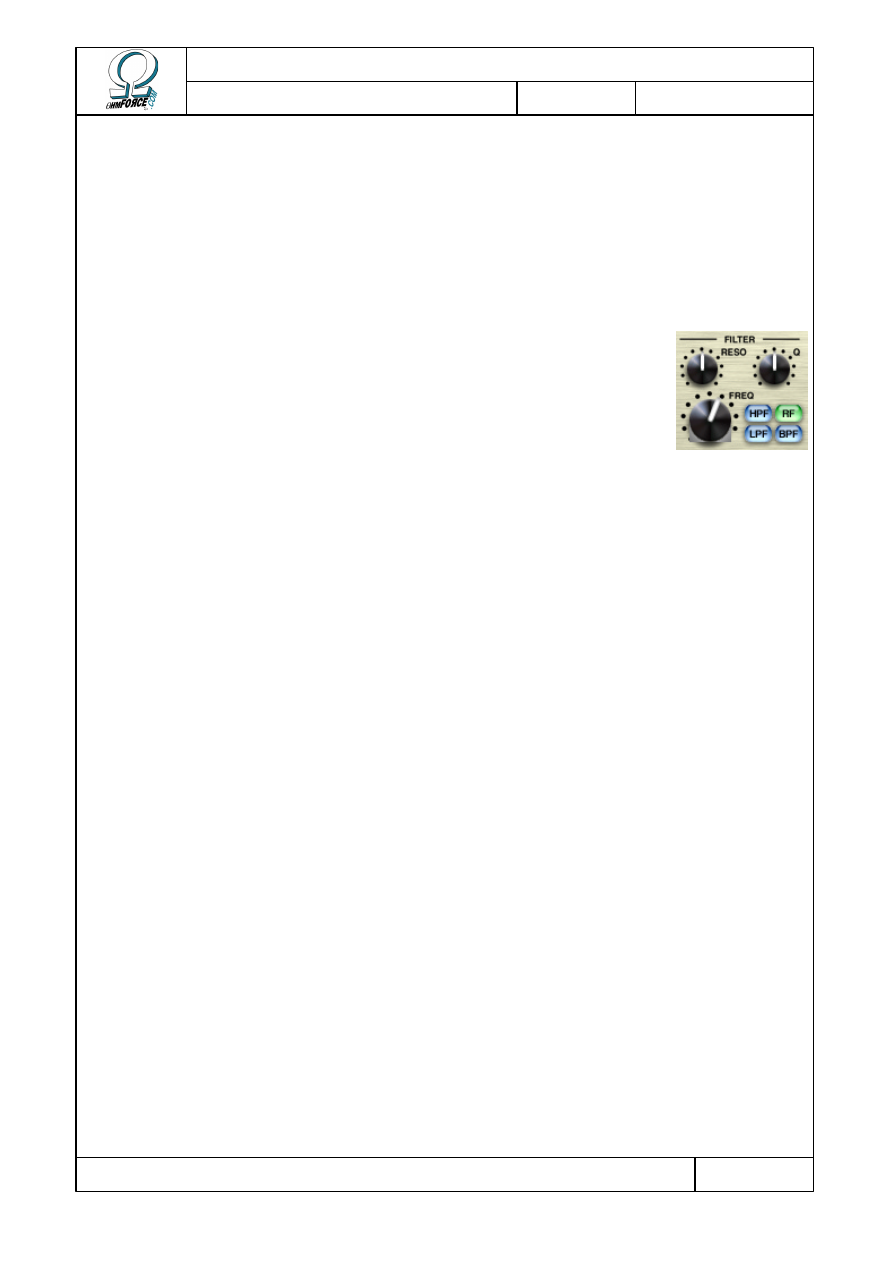
3.2.2.2
Resonant filter
The filter is the first effect applied to the delay line. It controls the
damping of the sound and can accentuate certain frequency bands.
•
T
YPE
You can select one of these four filters:
RF
Peak
Increases (wah-wah effect) or decreases (notch style) a particular
frequency range without altering the others. The bandwidth is defined by
Q, and the peak height by resonance. When the resonance is set to 0 dB,
the sound will not be modified. Positive resonance settings give a wha-
wha type effect whereas negative ones act like a notch filter and create
phasing sounds.
LPF Low-pass A filter that cuts all frequencies above a cutoff point. Thus, it allows only
frequencies beneath the cutoff to pass. When resonance is increased over
–3 dB, a peak is generated at the cut-off frequency, intensifying it.
HPF High-pass Similar to the low-pass filter, except that it rejects frequencies below the
cutoff point.
BPF Band-pass Passes all frequencies within a selected frequency band and rejects all
other frequencies. As with the peak filter, the bandwidth is given by Q.
However, in this case, Resonance only defines volume.
•
C
UTOFF
Controls the filter cut-off frequency.
•
R
ESONANCE
Resonance defines the gain of the signal at the cut-off frequency. It is an exact value for the
peak and the band-pass filters, but it is a bit less accurate for low-pass and high-pass filters.
The resonance level has to be manipulated very carefully: if it is too high, the delay line will
develop an auto-oscillation effect that could be undesirable. To prevent this, the resonance
level and the feedback level combined should be no greater than 0 dB. For instance, if the
feedback level is 50 % (–6dB), the resonance level should not exceed 6 dB.
•
Q
This parameter is used by the peak and the band-pass filters. It defines the bandwidth.
When Q is low, the band is wide, and the filter is less selective than when Q is high. When the
Copyright 1999–2003 – Ohm Force
Page 22/45
The Ohm Force Experience User Manual
V 1.0
Date
2003.06.12
Ref -
band is narrow its sound volume is reduced, so it might be necessary to increase the
resonance level.
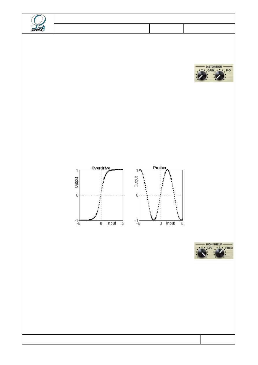
3.2.2.3
Distortion
Distortion occurs directly after the sound is filtered. It can degrade or
boost the sound, as you wish.
•
G
AIN
Controls the amount of distortion. When it is set to 0, the sound is unaltered.
•
C
OLOR
This fader defines the curve of the distortion. The effect changes depending on the curve
you choose.
•
Overdrive saturates the sound, giving it sharper overtones.
•
Puncher makes the sound more powerful, adding new tones in quite a different manner.
Using a high gain, and an input sound with sharp overtones, it is possible to obtain a
white noise effect.
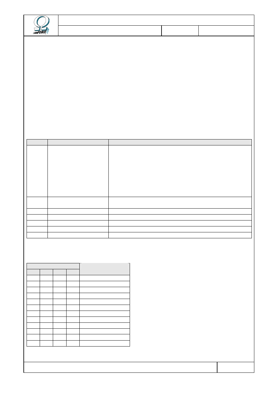
3.2.2.4
High-shelf filter
This filter slightly attenuates the sharp tones (first order low-pass
filter); this is often useful when distortion is used.
•
F
REQUENCY
The frequency above which the sound is attenuated.
•
L
EVEL
This sets the shelf level. In other words, the amount by which the volume of the high
frequencies is to be reduced. At 0 dB, the high-shelf does not modify the sound.
3.2.2.5
Miscellaneous
These buttons are located between the two delay lines.
Copyright 1999–2003 – Ohm Force
Page 23/45
The Ohm Force Experience User Manual
V 1.0
Date
2003.06.12
Ref -
•
S
ECOND DELAY
Click on this button to activate or cancel the second delay line.
•
C
ROSS
-
FEEDBACK
This fader is irrelevant unless the second delay line is activated. It regulates the separation
of the feedback from the two channels. When it is at the far left, the two lines feedback
independently, whereas when it is at the far right, they cross over.
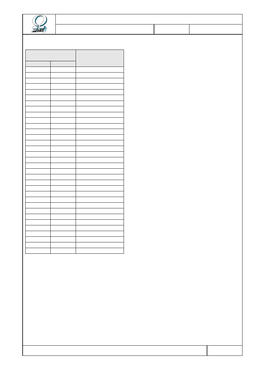
3.3 MIDI factory settings
3.3.1 Generic parameters
NRPN Parameter
Remark
0
Flags
This command can adjust many parameters at one time.
One can group functions to be activated by adding the
following values:
•
+32: Time unit in BPM
•
+16: Second delay line
•
+08: Sustained Loop Mode
•
+04: Delay 1 flush
•
+02: Delay 2 flush
1
Tempo
Has an effect only if the host application does not directly
control the tempo.
2
Predelay level
3
Feedback cross-fader
4
. . . LFO Period
5
. . . LFO Depth
6
. . . LFO Waveform
3.3.2 Predelays
NRPN for Tap...
1
2
3
4
Parameter
7
19 31 43 Time
8
20 32 44 . . . LFO Period
9
21 33 45 . . . LFO Depth
10
22 34 46 . . . LFO Waveform
11
23 35 47 Level
12
24 36 48 . . . LFO Period
13
25 37 49 . . . LFO Depth
14
26 38 50 . . . LFO Waveform
15
27 39 51 Pan
16
28 40 52 . . . LFO Period
17
29 41 53 . . . LFO Depth
18
30 42 54 . . . LFO Waveform
Copyright 1999–2003 – Ohm Force
Page 24/45
The Ohm Force Experience User Manual
V 1.0
Date
2003.06.12
Ref -
3.3.3 Delay lines
NRPN for delay
line...
1
2
Parameter
55
88
Level
56
89
Pan
57
90
. . . LFO Period
58
91
. . . LFO Depth
59
92
. . . LFO Waveform
60
93
Time
61
94
. . . LFO Period
62
95
. . . LFO Depth
63
96
. . . LFO Waveform
64
97
Feedback
65
98
. . . LFO Period
66
99
. . . LFO Depth
67
100
. . . LFO Waveform
68
101
Filter type
69
102
Filter cutoff
70
103
. . . LFO Period
71
104
. . . LFO Depth
72
105
. . . LFO Waveform
73
106
Filter resonance
74
107
. . . LFO Period
75
108
. . . LFO Depth
76
109
. . . LFO Waveform
77
110
Filter Q
78
111
. . . LFO Period
79
112
. . . LFO Depth
80
113
. . . LFO Waveform
81
114
Distortion type
82
115
Distortion amount
83
116
. . . LFO Period
84
117
. . . LFO Depth
85
118
. . . LFO Waveform
86
119
High-shelf cutoff
87
120
High-shelf level
Copyright 1999–2003 – Ohm Force
Page 25/45
The Ohm Force Experience User Manual
V 1.0
Date
2003.06.12
Ref -
3.3.4 LFO phases
One can also control LFO phase with the following NRPN.
NRPN LFO
121
Feedback cross-fader
122
Tap 1 Time
123
Tap 1 Level
124
Tap 1 Pan
125
Tap 2 Time
126
Tap 2 Level
127
Tap 2 Pan
128
Tap 3 Time
129
Tap 3 Level
130
Tap 3 Pan
131
Tap 4 Time
132
Tap 4 Level
133
Tap 4 Pan
134
Delay 1 Pan
135
Delay 1 Time
136
Delay 1 Feedback
137
Delay 1 Filter Cutoff
138
Delay 1 Filter Resonance
139
Delay 1 Filter Q
140
Delay 1 Distortion amount
141
Delay 2 Pan
142
Delay 2 Time
143
Delay 2 Feedback
144
Delay 2 Filter Cutoff
145
Delay 2 Filter Resonance
146
Delay 2 Filter Q
147
Delay 2 Distortion amount
Copyright 1999–2003 – Ohm Force
Page 26/45
The Ohm Force Experience User Manual
V 1.0
Date
2003.06.12
Ref -
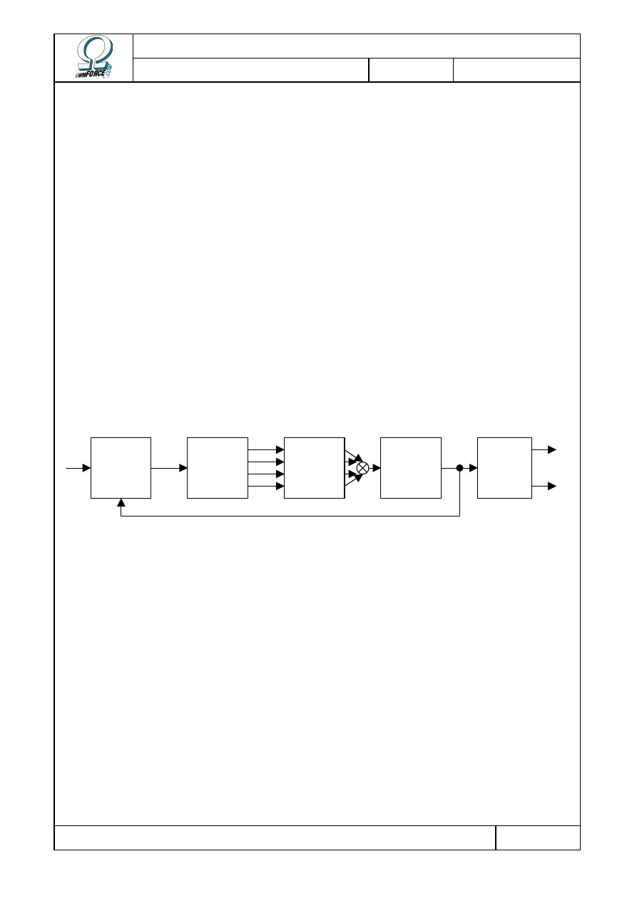
4. Predatohm
4.1 Functionality
This technical section explains how the guts of the Predatohm work. The Predatohm is a
multi-band distortion and dynamics processor. The process it uses can be divided into 5 steps:
•
First the input is merged with the feedback from “older” output.
•
The input is then split into up to 4 separate bands which the user can define by altering
the cutoff frequencies.
•
Dynamic setting and distortion effects are applied to each band; each band has its own
parameters.
•
The 4 bands are then mixed together before being injected into the tone unit.
•
Finally, there is optional stereo processing to widen the output.
Digital distortion sometimes introduces strange artifacts, mostly in the high frequencies,
known as aliasing. These are often inaudible, but in some cases can be a problem. If this
occurs, it is possible to get rid of them by oversampling the signal. Predatohm has an option
do this at a ratio of 4. Please note that the drawback of this feature is a higher CPU load.
Here is a diagram summarizing the Predatohm effect:
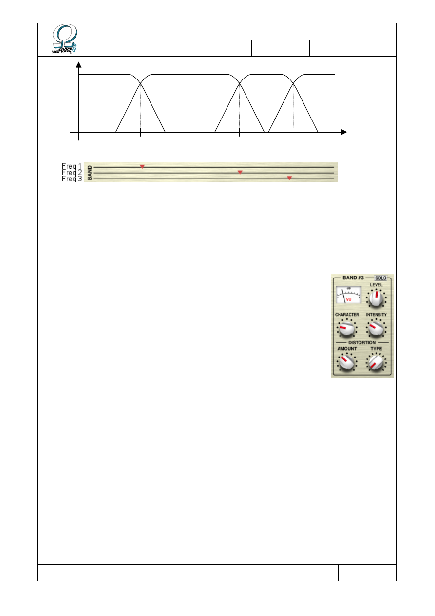
4.2 Bands
4.2.1 Splitting
Audio input can be split into separate bands, each defined by two frequencies, the lower and
upper limits. Compression and distortion can then be applied to each of these bands. The
Predatohm supports up to 4 distinct bands. Only 3 splitting frequencies are needed to define
these, as the highest and the lowest extremes are fixed at the limits of human hearing.
Feedback
processing
Band
split
Band
processing
Stereo
processing
Tone
settings
In
Out
L
Out
R
Copyright 1999–2003 – Ohm Force
Page 27/45
The Ohm Force Experience User Manual
V 1.0
Date
2003.06.12
Ref -
Users can set the three splitting frequencies by using the three dedicated knobs/faders. The
fader positions are constrained to ensure that Freq 1 = Freq 2 = Freq 3. The consequence of
this is that tweaking one knob may “push” the other ones in order to avoid boundary markers
crossing over. When the Predatohm is started, only band 1 is active because all the
frequencies are set at maximum. To make more bands appear, lower the splitting frequencies.
4.2.2 Band processing
The band processing is divided into 2 steps:
•
Dynamics
•
Distortion
All the following settings can be tuned separately for each band. On the
Funky skin, the same controls are present on each finger of the Predatohm
hand.
4.2.2.1
Dynamics
This stage is intended to alter the sound volume, enhancing or reducing transients. It is a
complex process but can be tuned using only two parameters.
•
I
NTENSITY
The intensity parameter determines how much the character setting alters the sound.
•
C
HARACTER
This determines the nature of the effect:
•
In the “Phat” zone, to the left, sound is compressed: dynamics are reduced, but the
sound appears to be louder and sustains for longer.
•
In the “Sharp” zone, to the right, sound is expanded: dynamics are increased and
attacks are emphasized, producing highly percussive sounds.
•
In the neutral position, the center, the sound is unmodified.
Frequency
Band 1
Band 2
Band 3
Band 4
Freq 1
Freq 2
Freq 3
Copyright 1999–2003 – Ohm Force
Page 28/45
The Ohm Force Experience User Manual
V 1.0
Date
2003.06.12
Ref -
4.2.2.2
Distortion
•
T
YPE
The distortion effect is then applied. The controls are located at the bottom of each band.
Predatohm supports 13 distortion types, which can be selected using the Type button – the red
dotty control on the Funky Skin.
•
A
MOUNT
The intensity of the distortion can be set by adjusting the input gain, which ranges from –20
dB to +40 dB. The higher the gain, the more distorted the sound. With almost every distortion
algorithm, if the gain is set to a low value, below 0 dB, the distortion will be unnoticeable. This
is useful if the distortion effect needs to be bypassed. You can compensate for the volume loss
by boosting the signal in the Mix section.
4.2.2.3
Mix
•
LEVEL
The volume can be tuned individually on each band. It can be set from –
∞
dB to +20 dB and
monitored on the vu-meter. You can also set the overall volume for all bands with the Master
volume knob (or fader for the Funky skin).
•
S
OLO
Activate this button if you want to cut out the other bands and listen to just the one
selected. It is possible to solo more than one band simultaneously. A right click inverts all the
solo settings.
4.3 End of the chain
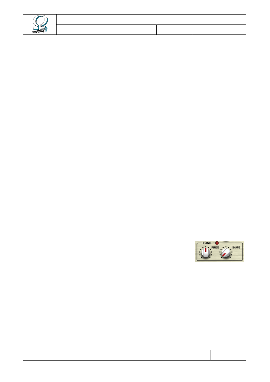
4.3.1 Tone
After band processing the signals are mixed together, and the tone
setting is applied in order to attenuate hyper-bright frequencies.
•
T
ONE SHAPE
This determines the “color” of the filter. Turned to the far left, it does nothing. In the mid
position, it is a simple 48 dB/octave low pass filter. Pushed to the right, this knob introduces a
little resonance.
•
T
ONE FREQUENCY
The tone frequency, ranging from 2 kHz to 8 kHz, determines the cutoff frequency of the
filter. Tweaking this can have a vast impact on final sound.
Copyright 1999–2003 – Ohm Force
Page 29/45
The Ohm Force Experience User Manual
V 1.0
Date
2003.06.12
Ref -
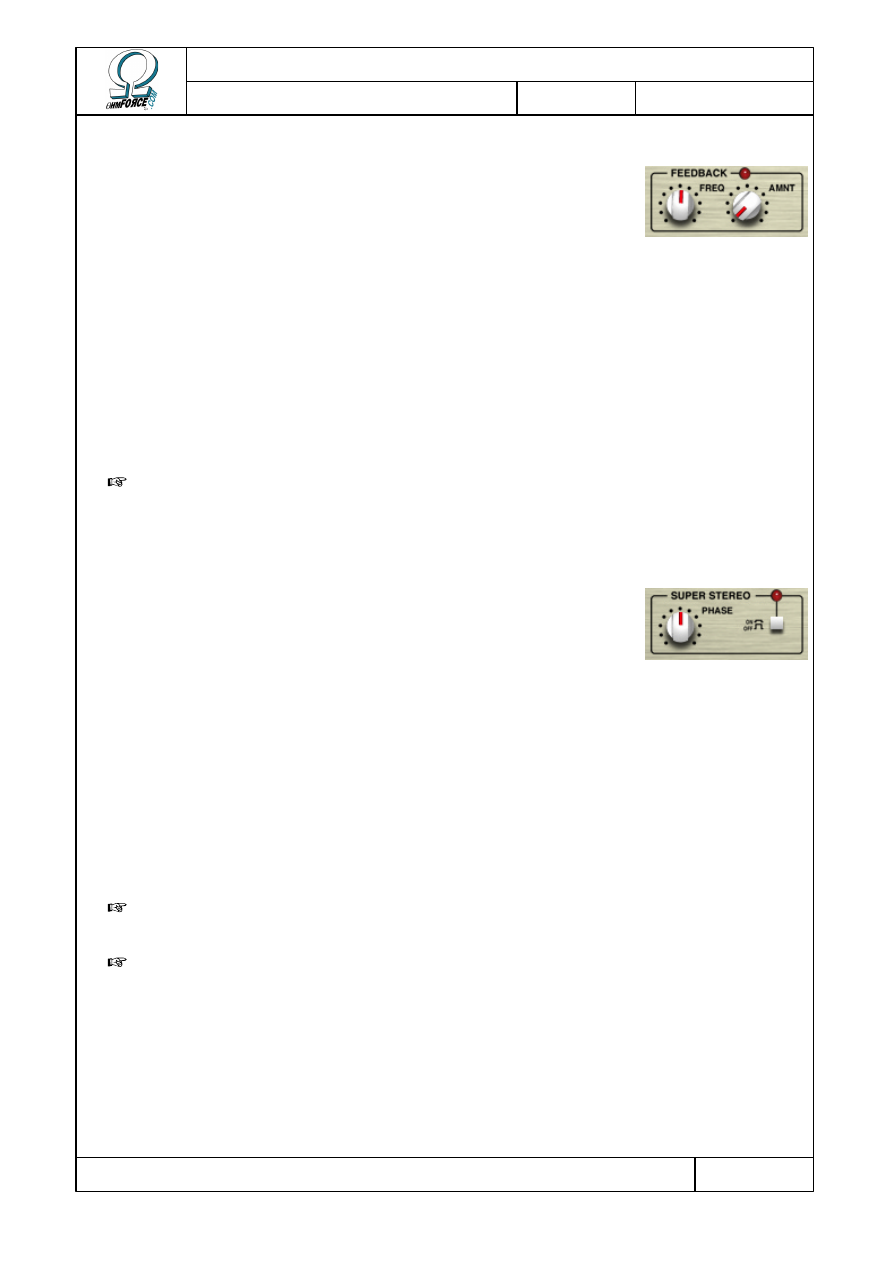
4.3.2 Feedback
The input stream is merged with the previously generated output
stream. This process can be tuned with 2 knobs:
•
F
REQUENCY
This can be set from 16 Hz to 1024 Hz. In a real acoustic environment, the frequency
corresponds to the distance separating the microphone from the loudspeaker. The sound
leaves the speaker, travels, is recorded by the microphone and amplified back through the
speaker. A low pitch would imply that the two are far apart.
•
A
MOUNT
The other parameter for feedback processing is the feedback amount (%), also controlled
by a knob. This parameter determines the simulated microphone sensitivity.
W
ARNING
: Be careful with the feedback. Large values will make it uncontrollable,
particularly if one of the bands has its dynamic processing set to “Phat” mode.
4.3.3 Stereo
If the host accepts stereo output from the plug-in, then you can
activate the stereo processing option. This adds an artificial stereo
effect by inverting and delaying the two output channels.
We recommend you use this option with care because, if the output channels are post-
mixed back to mono, the sound, or part of it, may disappear. The nature of the effect may also
vary with loudspeaker placement.
•
S
TEREO
O
N
/O
FF
Click on this button to activate or deactivate the stereo processing.
•
P
HASE
This sets the time differential between the left and right channels, ranging from 0 to 10 ms.
I
MPORTANT
: In all cases, Predatohm processing is done in mono. If the input is stereo, it
is converted to mono first. The stereo output just adds an artifical stereo feeling.
W
ARNING
: Sounds processed with 0 ms stereo-phase are not mono-compatible.
Copyright 1999–2003 – Ohm Force
Page 30/45
The Ohm Force Experience User Manual
V 1.0
Date
2003.06.12
Ref -
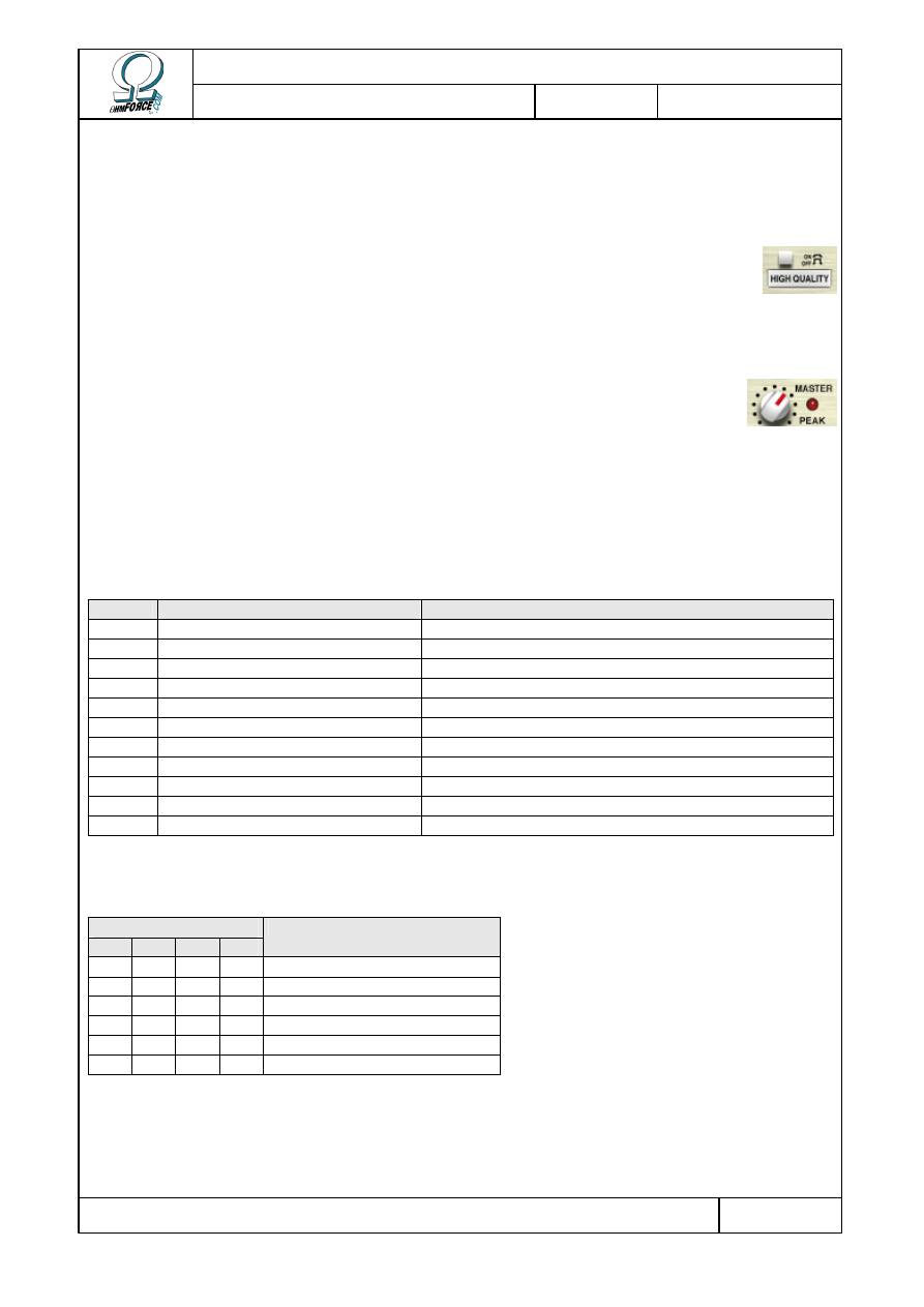
4.3.4 Master section
•
H
IGH
Q
UALITY
Press this button to activate oversampling. This is an optional Predatohm
feature: it allows you to reduce the unwanted aliasing effect produced by the
distortion process. Be aware, however, that this option increases CPU load! We
suggest you use it only for final mixdowns, or when aliasing is very noticeable.
•
M
ASTER
This knob sets the master volume. The LED indicates when the signal exceeds
the 0 dB peak. Should this happen, the signal is not altered, as most plug-in
standards supports floating point data and are not sensitive to clipping before
final output.
4.4 MIDI factory settings
4.4.1 Generic parameters
NRPN Parameter
Remark
0
Stereo Boost Switch
1
High Quality Switch
2
Tone Frequency
3
Tone Color
0 = Tone disabled
4
Stereo Amount
5
Feedback Amount
0 = Feedback disabled
6
Feedback Frequency
7
Master Volume
9
Band 1-2 Split Frequency
Max = disables bands 2, 3 and 4
10
Band 2-3 Split Frequency
Max = disables bands 3 and 4
11
Band 3-4 Split Frequency
Max = disables band 4
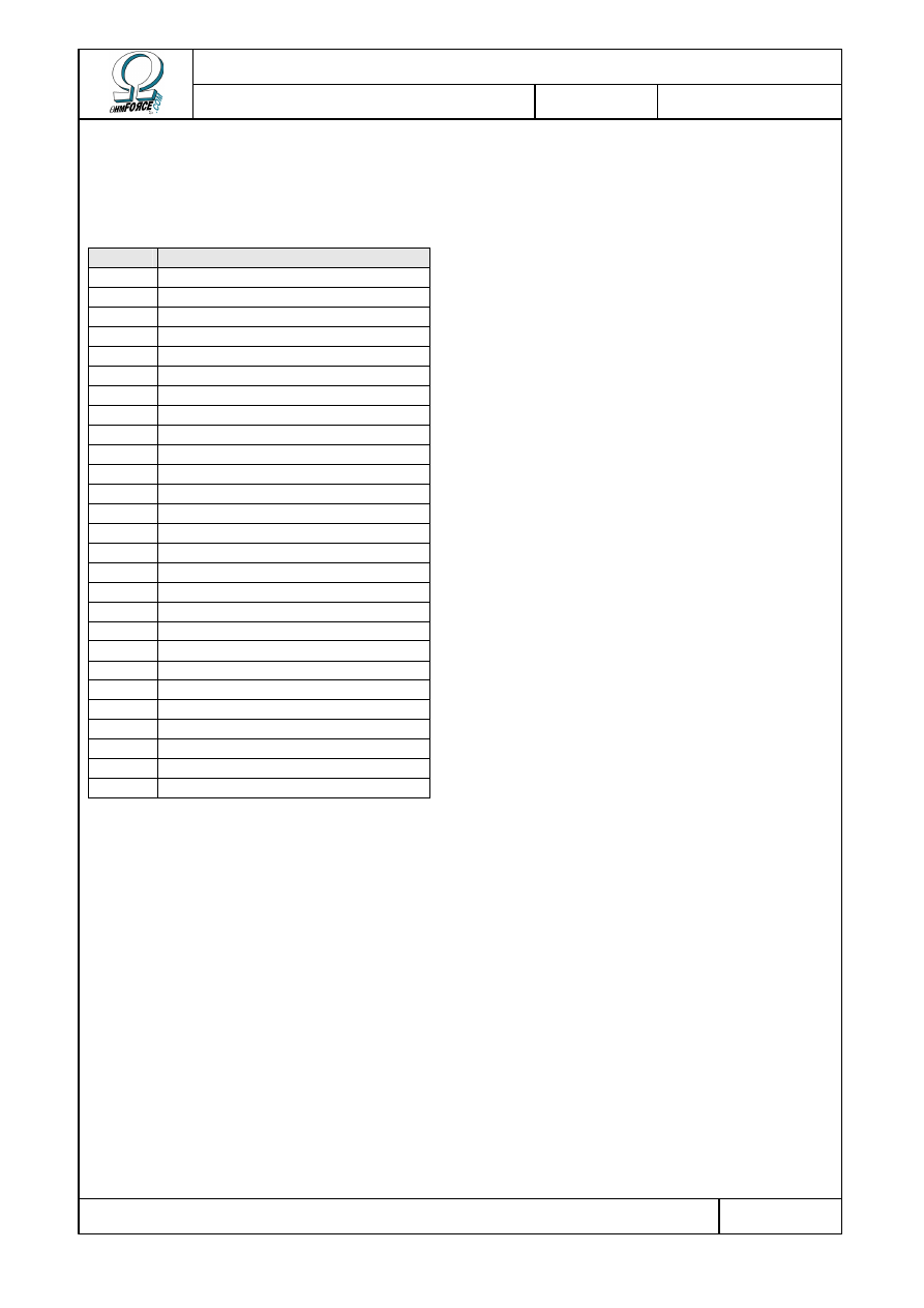
4.4.2 Band parameters
NRPN for Band...
1
2
3
4
Parameter
12
19 26 33 Character
13
20 27 34 Intensity
14
21 28 35 Distortion Amount
15
22 29 36 Distortion Type
16
23 30 37 Level
17
24 31 38 Switch for band solo
Copyright 1999–2003 – Ohm Force
Page 31/45
The Ohm Force Experience User Manual
V 1.0
Date
2003.06.12
Ref -
5. Hematohm
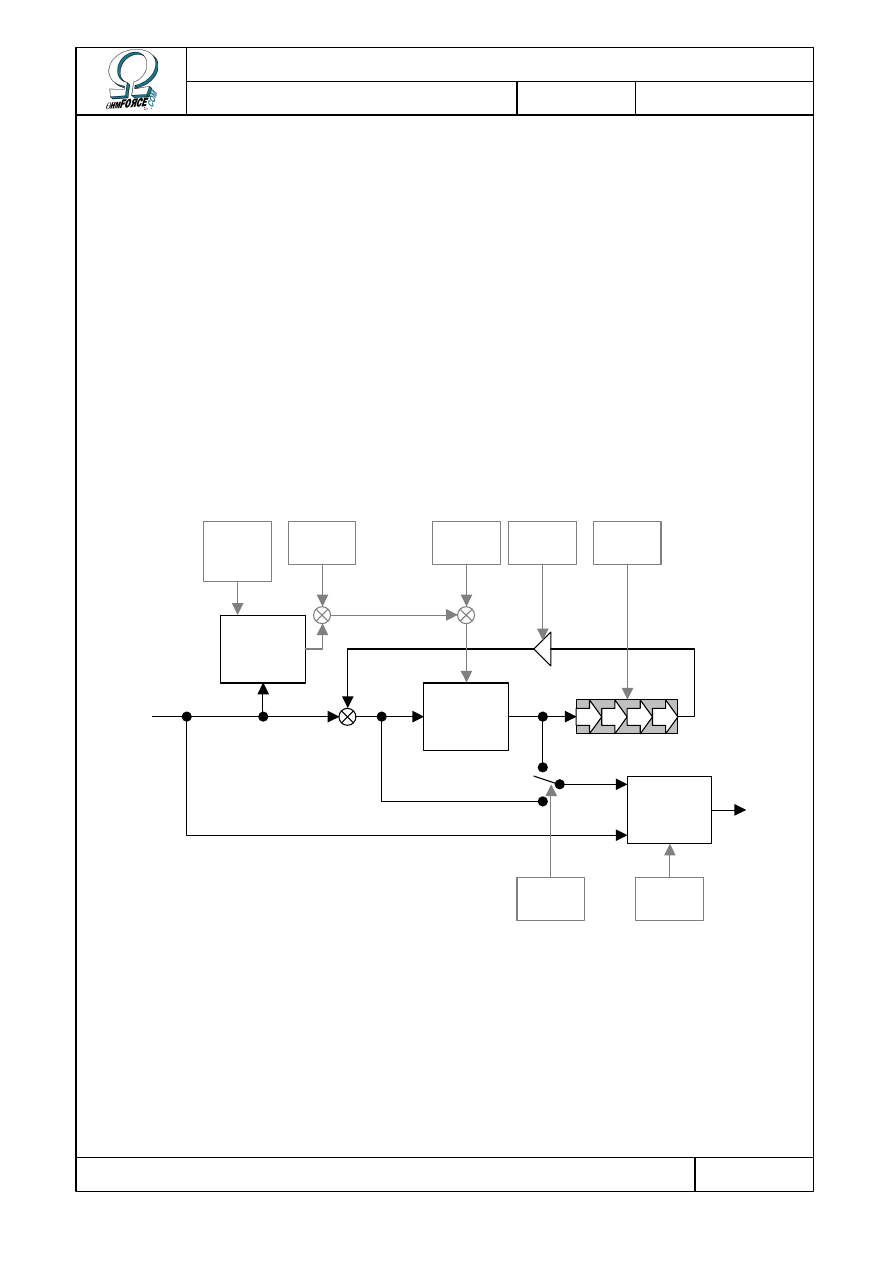
5.1 Functionality
5.1.1 Architecture
This plug-in is a frequency shifter, augmented with an LFO, an envelope follower and a
delay. The process can be divided into 3 steps:
•
The input volume is detected by the envelope follower.
•
The signal spectrum is shifted and delayed.
•
The input and the shifted sounds are combined
Here is a diagram that summarizes the Hematohm effect:
5.1.2 A frequency shifter?
First, this is not a pitch shifter! The two are often mixed up. A pitch shifter is an effect that
can change the tuning of a sound, by transforming a piano note tuned in C4 into an A3 note,
for example. It is achieved by multiplying all frequency components by a constant. Thus the
ratio between harmonics is preserved and the sound maintains its timbre.
Frequency
shifter
Envelope
follower
Crossfader
Dry / Wet
In
Out
Delay line
Delay
feedback
Dry / Wet
mix
Direct
routing
Delay
time
Shift
amount
Amount,
Attack,
Decay
LFO
Modulation
signal
Copyright 1999–2003 – Ohm Force
Page 32/45
The Ohm Force Experience User Manual
V 1.0
Date
2003.06.12
Ref -
A frequency shifter is different. The frequencies are added according to a constant
frequency, rather than being multiplied. A ring modulator works in this manner, but it is
limited to building a mirror image in the lower part of the spectrum, and it doesn't support
negative shifting.
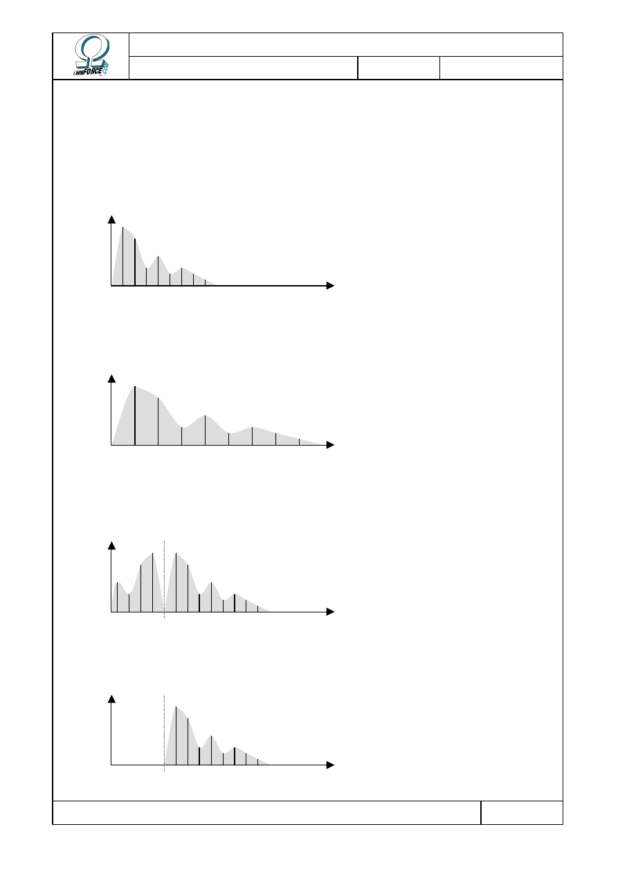
Here is a comparison of these various effects on the spectrum of a sound:
•
Unprocessed sound
•
Pitch shifting one octave up
•
Ring modulation
•
Frequency shifting
Freq
Freq
Freq
Ring frequency
Freq
Shift frequency
Copyright 1999–2003 – Ohm Force
Page 33/45
The Ohm Force Experience User Manual
V 1.0
Date
2003.06.12
Ref -
5.1.3 Frequency shifter typical usage
A consequence of this frequency shifting is that the harmonics get out of tune. Their
relationships with the fundamental frequency are broken, with outlandish results: making an
acoustic guitar sound like a bell, for example.
However, with certain sounds, and the right frequencies, it is possible to maintain a good
relationship between harmonics. Thus the sound is changed but its pitch remains identifiable.
Small shifting frequencies keep the sound coherent and are useful to obtain slight variations in
the tone.
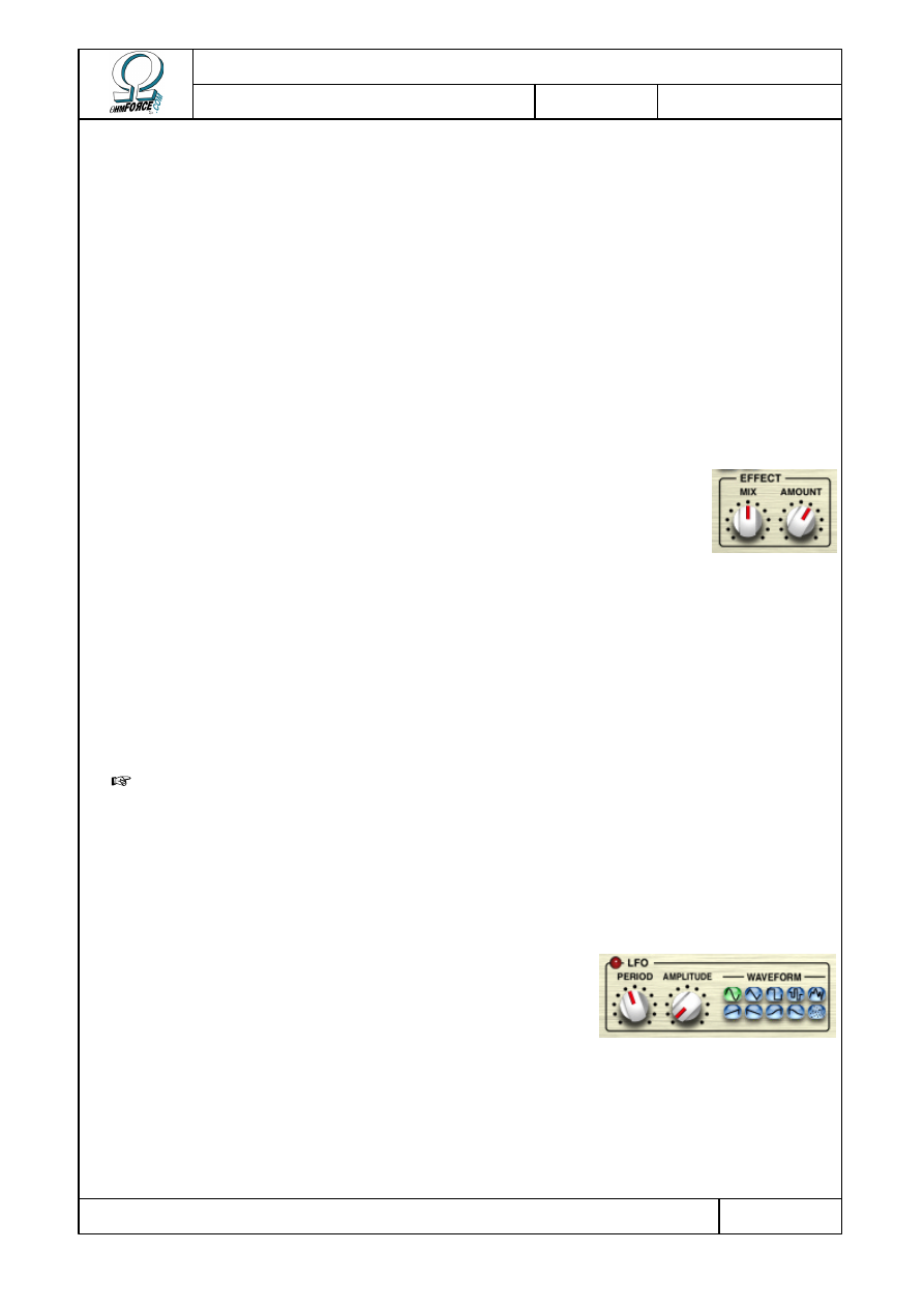
5.2 Effect
In this section you'll find instructions for the main buttons that control
the Hematohm.
•
A
MOUNT
The Amount is the main effect control. It is the shifting frequency, in Hz.
It can be positive or negative. When the amount is 0 Hz, the center
position, it has no effect.
•
M
IX
The Mix button dictates how the input and processed sound are mixed together to form the
output signal. Turned to the left, the effect is completely bypassed, and the input is directly
connected to the output. At the far right, the output sound contains no trace of the
unprocessed input.
T
IP
: You can obtain nice phaser effects by setting the Amount parameter to a value
below 10 Hz and then setting the Mix button to its center point.
5.3 Modulation
5.3.1 LFO
It is possible to make the shifting frequency - the
Effect/Amount parameter - change constantly using the LFO.
The Low Frequency Oscillator causes oscillations or random
changes. See the Common Features section for more
information about LFOs.
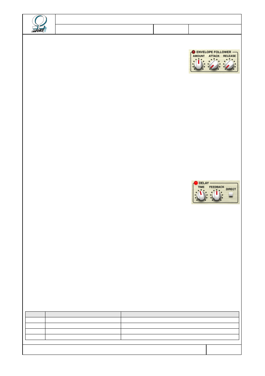
Copyright 1999–2003 – Ohm Force
Page 34/45
The Ohm Force Experience User Manual
V 1.0
Date
2003.06.12
Ref -
5.3.2 Envelope follower
The envelope follower detects the input sound volume and
modifies the shifting frequency according to the envelope
shape. The louder the sound, the more the shifting frequency
is affected.
•
A
MOUNT
Indicates how the shifting frequency should be modified. At the center position of 0 Hz, the
envelope follower has no effect.
•
A
TTACK
The time it takes the envelope to respond to the attacks in the input sound (i.e. rises in
input volume).
•
R
ELEASE
The time it takes the envelope to respond to the decays in the input sound (i.e. Drops in the
input volume).
5.4 Delay
The unit also has a delay, which can be used with the
shifter in its feedback path. The delay effect repeats the
sound regularly. Sounds created can have an infinitely
increasing or decreasing pitch.
•
T
IME
The time between each repetition.
•
F
EEDBACK
The amount of delayed sound which is re-injected into the delay. 0 % means no re-
injection.
•
D
IRECT ROUTING
This switch selects where the effect occurs in the delay circuitry. In “Feedback” mode, the
effect is only applied to the feedback path, thus the shifting is heard only after one repetition.
In “Direct” mode, it is applied to the direct signal path before it is fed into the delay.
5.5 MIDI factory settings
NRPN Parameter
Remark
0
Tempo
1
Dry/Wet Mix
2
Effect Amount
3
LFO Period
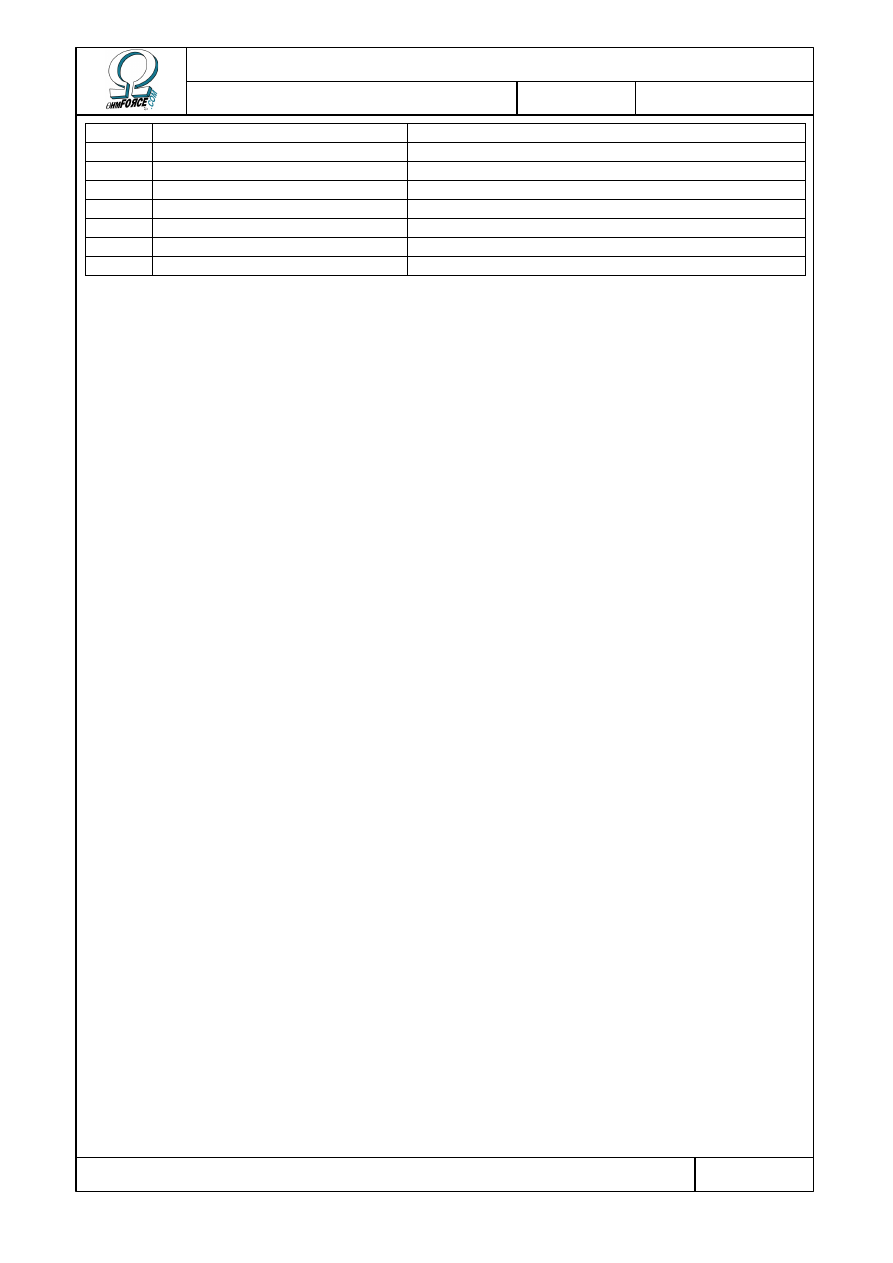
Copyright 1999–2003 – Ohm Force
Page 35/45
The Ohm Force Experience User Manual
V 1.0
Date
2003.06.12
Ref -
4
LFO Depth
5
LFO Waveform
6
Envelope Amount
7
Envelope Attack Time
9
Envelope Release Time
10
Delay Routing
0 = Direct
11
Delay Time
12
Delay Feedback

Copyright 1999–2003 – Ohm Force
Page 36/45
The Ohm Force Experience User Manual
V 1.0
Date
2003.06.12
Ref -
6. Mobilohm
6.1 Functionality
6.1.1 What is a phaser ?
A basic phaser is created by running a signal through an all-pass filter (a filter that does not
change the frequency content of the signal, only the phase). Then the filtered signal is added
to the original one. This operation creates notches in the signal spectrum. The number and
position of the notches depends on the all-pass filter design.
A variable phaser, the kind typically used by musicians, is created by altering the all-pass
filter parameters. This causes the notch frequencies to move continuously, generating that well
known phasing sound.
The phaser effect is close to, but somewhat different from, the flanger effect. The latter is
achieved by mixing a signal with a delayed version of itself. Adding a delay back into a signal
creates a particular kind of filter called a “comb”, which contains equally spaced peaks and
notches. If the delay is then varied constantly it moves the notch frequencies, creating a
flanging effect.
Both effects result from filtering the signal with a notched, time shifting, filter. The reason
they sound so different is that the notches are equally spaced in a flanger, but not in a phaser.
Furthermore, the phaser filter is generally smoother, and the flanger uses a delay line while
the phaser does not.
6.1.2 Architecture
The Mobilohm is more than just a simple phaser. The effect consists of three main stages:
•
First the signal is colored with a filter.
•
Then the signal is directed to four identical phasing cells.
•
· Finally, the colored signal is mixed with the four phased signals from the cells.
Here is a diagram summarizing the Mobilohm effect:
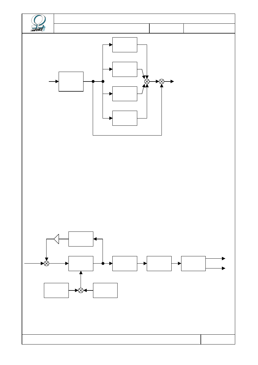
Copyright 1999–2003 – Ohm Force
Page 37/45
The Ohm Force Experience User Manual
V 1.0
Date
2003.06.12
Ref -
You can turn any of the cells off by setting its gain knob to –8 dB. It's also possible to
remove the direct output of the colored signal from the final mix in the same manner.
6.1.3 Cell description
Each cell applies a phasing effect and some other processing, allowing you to get extremely
creative results. For starters, each cell contains a feedback setting, which loops the processed
signal back to the input to be processed again; this reinforces the effect, making it fatter.
It's also possible to stop the oscillations and to set the phase manually as on old analog
phaser. The phased signal can then be filtered by a bandpass filter. You can control the cutoff
frequency and the bandwidth of the filter.
Color
filter
Cell 2
Cell 1
Cell 3
Cell 4
In
Out
Cell Input
Phasing
filter
Phase
oscillator
Manual
phase
Feedback
coloring
Band-pass
filter
Distortion
Panoramic
processing
Left cell
output
Right cell
output
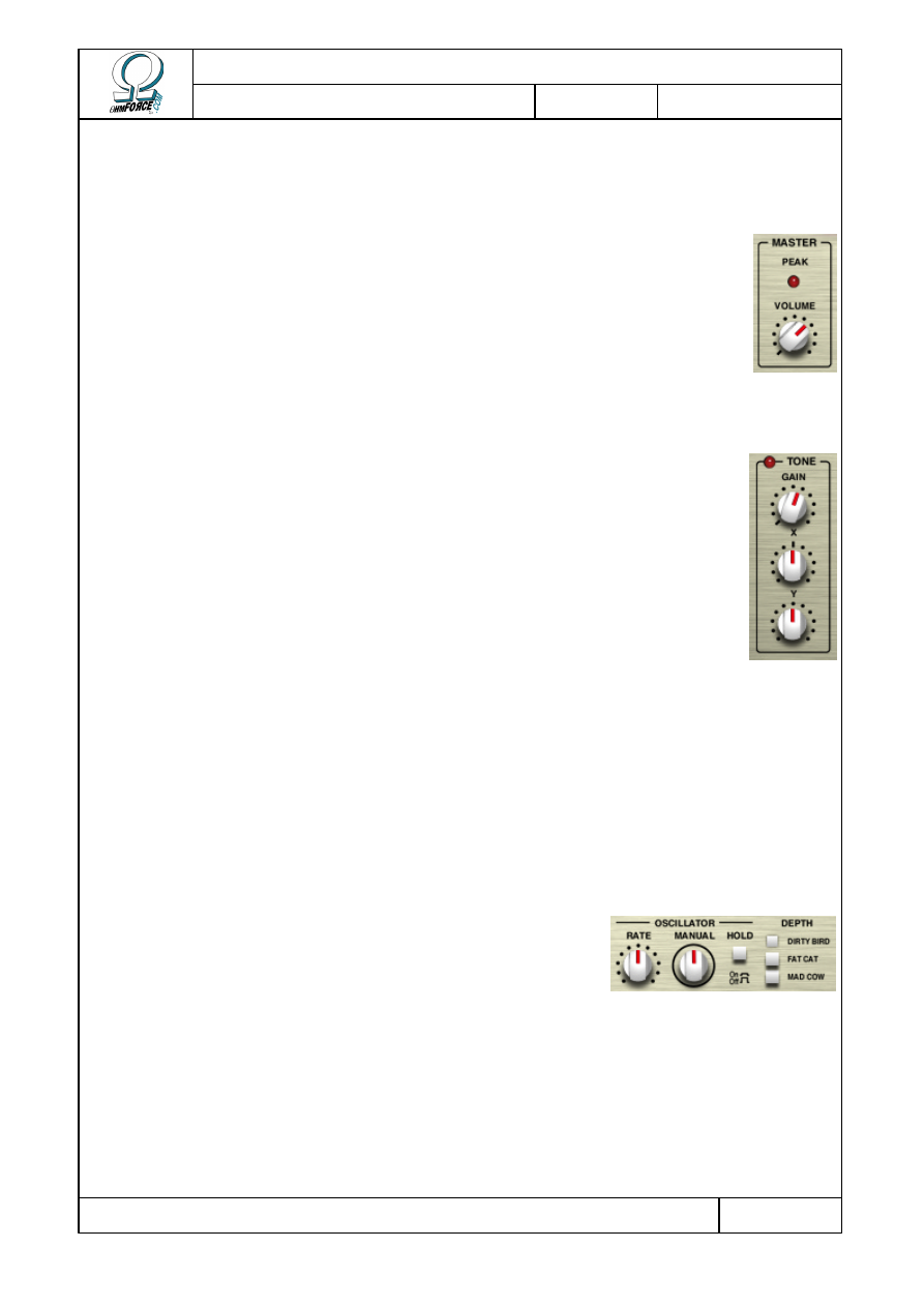
Copyright 1999–2003 – Ohm Force
Page 38/45
The Ohm Force Experience User Manual
V 1.0
Date
2003.06.12
Ref -
6.2 Using Mobilohm
6.2.1 Master volume
The Volume is the total effect output gain. Turning it to –8 dB will mute the
output. The peak LED blinks every time the outputs jumps over 0 dB.
6.2.2 Tone
This controls the coloring filter which feeds the four phaser cells.
•
G
AIN
The gain knob controls the output of the Tone section to the final mix. Thus,
setting the level to –8 dB will prevent you from hearing the colored signal,
although the cells will still process the signal.
•
T
ONE
X
This setting controls the color intensity of the Tone section’s filter. Is T
ONE
X is
set to 0 %, the signal won't be colored, whatever the value of T
ONE
Y.
•
T
ONE
Y
T
ONE
Y modifies the frequency of the filtering bands managed by T
ONE
X. In other words, it
dictates the type of color. The idea behind the T
ONE
Y LFO is to provide an additional timbre
oscillation.
6.2.3 Cells
6.2.3.1
Oscillator
This is the pure phasing section of the cell, which creates the
sweeping effect.
•
R
ATE
The rate controls the frequency of the modulation. A slow setting will result in a slowly
shifting sound. The rate can be set relative to the tempo, so rhythmic effects can be achieved.
Setting the rate to a short period modulates the signal so quickly that audible harmonics
appear.
•
H
OLD
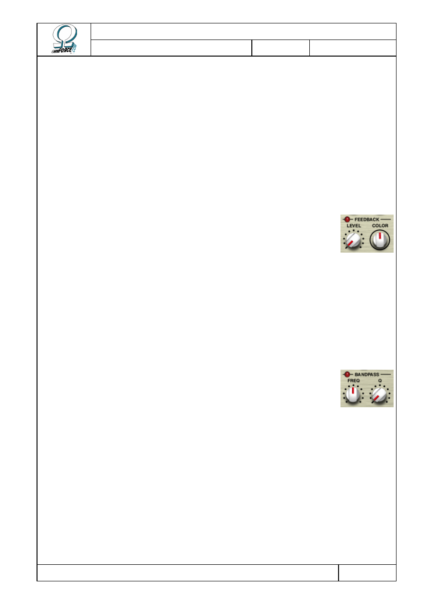
Copyright 1999–2003 – Ohm Force
Page 39/45
The Ohm Force Experience User Manual
V 1.0
Date
2003.06.12
Ref -
This switch allows you to freeze the modulation. You can then use the M
ANUAL
knob to
adjust the phase or achieve a manual phasing effect. You can also use it when H
OLD
is off, but
the result is less noticeable since the phase is already oscillating constantly.
•
M
ANUAL
Changes the phase of the oscillation. Best used with H
OLD
on. Freezing the oscillations and
applying a small amount of LFO to M
ANUAL
can achieve an interesting effect. The oscillations
will alter the timbre slightly – now turn the M
ANUAL
knob to find the timbre you want.
•
D
EPTH
This changes the complexity of the all-pass filter, affecting the number of notches created,
and, as a consequence, the fatness of the effect.
6.2.3.2
Feedback
Feedback is an important phaser feature. With it, you can dramatically
change the color of the phased sound. When no feedback is involved, you
have to mix the phased signal with the pure colored sound (see the Tone
section) to hear changes. With enough feedback, there is no more need for
the colored sound, the phased signal having a texture of its own.
•
L
EVEL
This is the amount of sound from the output injected back into the phaser input. If it is
equal to 0 %, the feedback is disabled.
•
C
OLOR
This setting alters the sound of the feedback.
6.2.3.3
Filter
This is a 2-pole band-pass filter, applied at the output of phasing stage. It
limits the sound to a certain frequency band in the spectrum. When several
cells are mixed, sound becomes fluid and the effect is a bit diminished. By
selecting the bands carefully, so that they do not overlap, it is possible to
achieve far more interesting effects.
•
F
REQUENCY
Changes the center frequency of the band.
•
Q
Sets the selectivity of the filter. With low Q settings, the filter has a wide band and allows a
broad frequency range to pass. With high Q settings, the band is narrow and therefore very
colored. The leftmost knob position disables the filter.
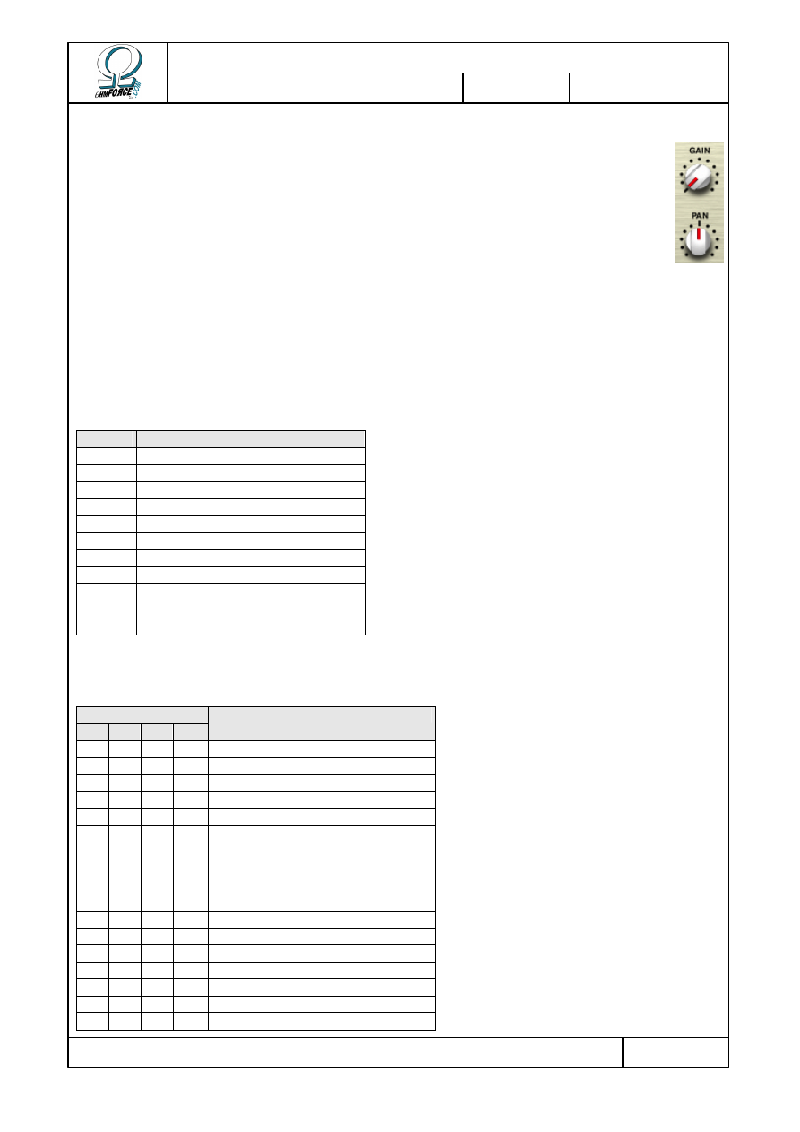
Copyright 1999–2003 – Ohm Force
Page 40/45
The Ohm Force Experience User Manual
V 1.0
Date
2003.06.12
Ref -
6.2.3.4
Mix
•
G
AIN
This parameter controls the output level of the cell. Turning it to –8 dB will
disable the cell.
•
P
AN
This Defines the stereophonic position of the cell in the final mix. The cell output
is already stereo, so be careful when panning a sound completely to the right or
the left.
6.3 MIDI factory settings
6.3.1 Generic parameters
NRPN Parameter
0
Tempo
1
Master Volume
2
Tone Volume
3
Tone X
4
. . . LFO period
5
. . . LFO depth
6
. . . LFO waveform
7
Tone Y
8
. . . LFO period
9
. . . LFO depth
10
. . . LFO waveform
6.3.2 Cell parameters
NRPN for Cell…
1
2
3
4
Parameter
11 39 67 95 Cell gain
12 40 68 96 Cell pan
13 41 69 97 . . . LFO period
14 42 70 98 . . . LFO depth
15 43 71 99 . . . LFO waveform
16 44 72 100 Cell oscillator depth
17 45 73 101 Cell oscillator hold
18 46 74 102 Cell oscillator rate
19 47 75 103 . . . LFO period
20 48 76 104 . . . LFO depth
21 49 77 105 . . . LFO waveform
22 50 78 106 Cell oscillator man phase
23 51 79 107 . . . LFO period
24 52 80 108 . . . LFO depth
25 53 81 109 . . . LFO waveform
26 54 82 110 Cell feedback level
27 55 83 111 . . . LFO period
Copyright 1999–2003 – Ohm Force
Page 41/45
The Ohm Force Experience User Manual
V 1.0
Date
2003.06.12
Ref -
28 56 84 112 . . . LFO depth
29 57 85 113 . . . LFO waveform
30 58 86 114 Cell feedback color
31 59 87 115 . . . LFO period
32 60 88 116 . . . LFO depth
33 61 89 117 . . . LFO waveform
34 62 90 118 Cell filter frequency
35 63 91 119 . . . LFO period
36 64 92 120 . . . LFO depth
37 65 93 121 . . . LFO waveform
38 66 94 122 Cell filter Q
6.3.3 LFO phases
One can also control LFO phase with the following NRPN.
NRPN LFO
123
Tone X
124
Tone Y
125
Cell 1 pan
126
Cell 1 oscillator rate
127
Cell 1 man phase
128
Cell 1 feedback level
129
Cell 1 feedback color
130
Cell 1 filter frequency
131
Cell 2 pan
132
Cell 2 oscillator rate
133
Cell 2 man phase
134
Cell 2 feedback level
135
Cell 2 feedback color
136
Cell 2 filter frequency
137
Cell 3 pan
138
Cell 3 oscillator rate
139
Cell 3 man phase
140
Cell 3 feedback level
141
Cell 3 feedback color
142
Cell 3 filter frequency
143
Cell 4 pan
144
Cell 4 oscillator rate
145
Cell 4 man phase
146
Cell 4 feedback level
147
Cell 4 feedback color
148
Cell 4 filter frequency
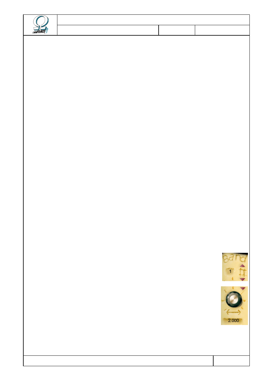
Copyright 1999–2003 – Ohm Force
Page 42/45
The Ohm Force Experience User Manual
V 1.0
Date
2003.06.12
Ref -
7. Frohmage
7.1 Functionality
This part is a bit technical, but it will help you understand structure of the Frohmage,
making it easier to get great results quickly. This plug-in is a multi-band resonant filter: it is
made of a resonant low-pass filter running in parallel with multiple band-pass filters. These are
then followed by a distortion stage.
The low-pass filter (LPF) passes only those frequencies below a certain threshold point,
known as the cutoff frequency. At the cutoff point there is a peak in the frequency response,
known as the resonance. This emphasizes a very small frequency range, coloring the sound.
Bandpass filters only allow small frequency ranges above the cutoff frequency to pass. All
the bands are equally frequency-spaced, which increase the sound coloration. It is also
possible to delay the sound of each band.
7.2 Controls
The user interface is divided into several distinct parts :
•
Presets / Setup. These are covered in the “Common feature” section.
•
Band control
•
Central panel
•
Distortion
The Frohmage has no LFO or Main Edit section. The parameter values are given below the
corresponding knobs.
7.2.1 Band control
•
N
UMBER OF BANDS
This parameter changes the number of bands, between 1 and 16. 1 means
only the LPF is active.
•
B
AND SPACING
Bands are regularly spaced; this parameter defines the size of gap between
adjacent bands.
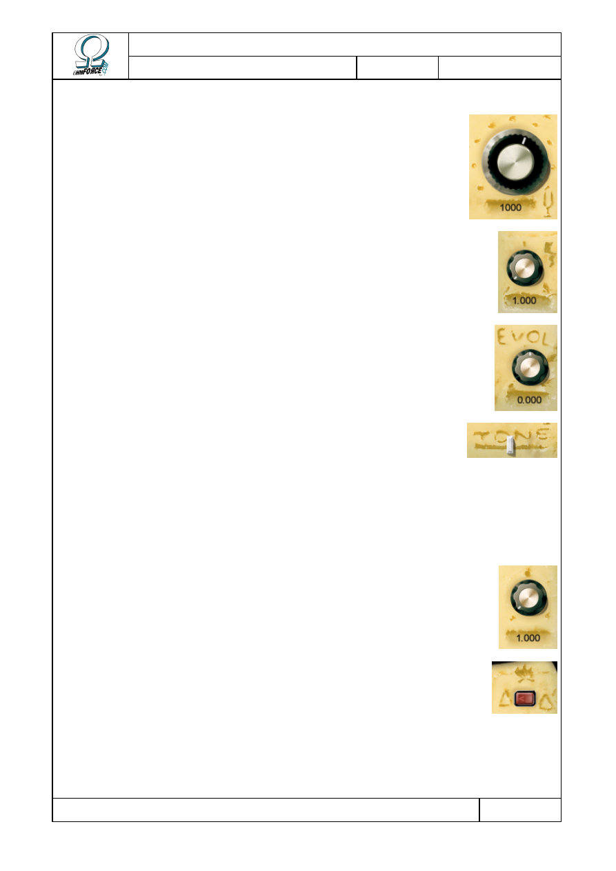
Copyright 1999–2003 – Ohm Force
Page 43/45
The Ohm Force Experience User Manual
V 1.0
Date
2003.06.12
Ref -
7.2.2 Central panel
•
C
UTOFF FREQUENCY
The main filter control. It modifies the filter cutoff frequency and
therefore its tonality.
•
R
ESONANCE
This knob controls the peak level at the cutoff frequency. The higher it
is, the more distinct the tone is.
•
E
VOLUTION
This Knob affects the delay times of all the bands. When it is at the
middle position, there is no delay. When the knob is turned to the left, the
lower bands are more delayed, and when the knob is turned to the right,
the higher bands are more delayed.
•
T
ONE
The filter output signal is divided into two parts: the LPF output and the
BPF output. With the tone parameter, you can change the balance between
the LPF and BPF sections. When the fader is set to the left, only the LPF
output can be heard. When it is set to the right, the balance is reversed
and only the BPF output can be heard.
7.2.3 Distortion
•
A
MOUNT
This parameter controls the distortion amount. Distortion is created by
softly clipping the signal.
•
R
OUTING
The distortion will process the whole signal if this button is set to the
left position, or the LPF output only if set to the right position.
Copyright 1999–2003 – Ohm Force
Page 44/45
The Ohm Force Experience User Manual
V 1.0
Date
2003.06.12
Ref -
7.3 MIDI factory settings
NRPN Parameter
0
Filter Cutoff Frequency
1
Resonance
2
Number of bands
3
Distortion gain
4
Distortion routing
5
Band Spacing
6
Evolution
7
Tone

Copyright 1999–2003 – Ohm Force
Page 45/45
The Ohm Force Experience User Manual
V 1.0
Date
2003.06.12
Ref -
8. Credits and thanks
The following people have worked or still work in the Ohm Force team:
Franck Bacquet
Yellow Force
Team management, programming
Vincent Birebent
Mauve Force
Web development, marketing and communication
Julien Bœuf
Blue Force
Programming
Eric Cestari
Grey Force
Web development
Raphaël Dingé
Fuchsia Force
Product design, Macintosh programming
Ian Finney
Gold Force
Communication
Vincent Frison
Orange Force
Web development
Eric Gougaud
Green Force
Team management
Thomas Legrand
Black Force
Accounting
Gregory Makles
Red Force
Product and web design, artwork
Jérôme Noël
Ivory Force
Product design, programming
Laurent de Soras
Plum Force
Product design, programming
Special thanks to Chris MacLeod, Dave Spiers and the whole GMedia team for their
invaluable support. Thank also to all the beta-testing program participants.
And in no particular order:
Angus Hewlett and Rhiannon Bankston-Thomas from Fxpansion, Frederique Bœuf, Hélène
Zanni, Jonathan Bidgood, Robert Robichon and the #musicdsp people on EFNet.
Wyszukiwarka
Podobne podstrony:
The Gateway Experience Complete Hemi Sync Gateway Experience Manual (j angielski)
ebook occult The Psychedelic Experience A manual based on the Tibetan Book of the Dead
Complete Hemi Sync Gateway Experience Manual
Experience bramy Manual
Manual Complete Hemi Sync Gateway Experience
EXPERIENTIAL
PANsound manual
als manual RZ5IUSXZX237ENPGWFIN Nieznany
hplj 5p 6p service manual vhnlwmi5rxab6ao6bivsrdhllvztpnnomgxi2ma vhnlwmi5rxab6ao6bivsrdhllvztpnnomg
BSAVA Manual of Rabbit Surgery Dentistry and Imaging
Okidata Okipage 14e Parts Manual
Bmw 01 94 Business Mid Radio Owners Manual
Manual Acer TravelMate 2430 US EN
manual mechanika 2 2 id 279133 Nieznany
4 Steyr Operation and Maintenance Manual 8th edition Feb 08
Oberheim Prommer Service Manual
cas test platform user manual
Kyocera FS 1010 Parts Manual
więcej podobnych podstron