
Army TB 11-5820-1130-10-1
Air Force TO 31R2-2PSC5-8-1
TECHNICAL BULLETIN
OPERATOR’S GUIDE
RADIO SET,
AN/PSC-5
(SPITFIRE)
(NSN 5820-01-366-4120)
(EIC: N/A)
This bulletin supersedes TB 11-5820-1130-10-1 dated 1 July 1999, which shall
be destroyed in accordance with applicable security regulations.
Distribution authorized to US Government agencies and their contractors only
for official use or for administrative or operational purposes. This determination
was made on 15 Feb 1996. Army requests for this document will be referred to
Commander, US Army Communications-Electronics Command Fort
Monmouth, ATTN: AMSEL-LC-LEO-E-ED-P, Fort Monmouth, New Jersey
07703-5000. Air Force requests for this document shall be referred to OO-
ALC-TIED, Hill AFB, Utah 84056-5820.
DESTRUCTION NOTICE—Destroy by any method that will prevent disclosure
of contents or reconstruction of the document.
HEADQUARTERS, DEPARTMENT
OF THE ARMY AND AIR FORCE
31 DEC 2002
Page
#
Page
#
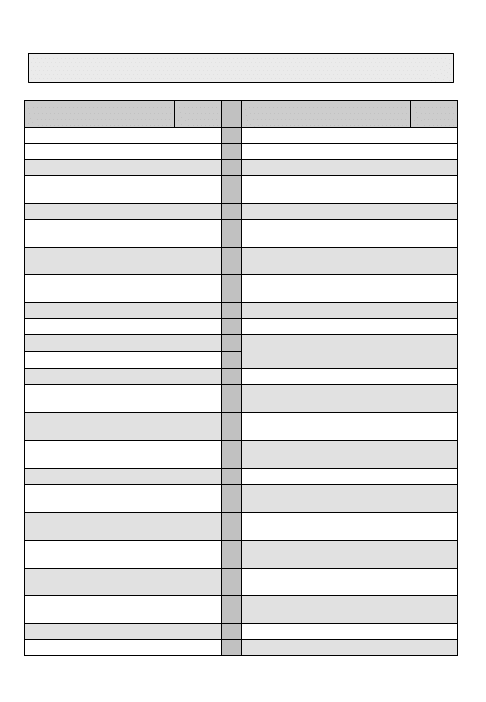
Table of Contents
Guard List
35
List of Tables
1
25-kHz DAMA Preset(s)
36
Introduction
2
25-kHz DAMA Service Preset(s)
37
Load COMSEC Key(s)
3,4
Quick Start to 25-kHz DAMA
Service
38
Load Orderwire Key
5,6
25-kHz AC DAMA Hot Keys
39
Key Update
7
25-kHz AC DAMA Manual
Service Setup
40
Connect Data Devices
8-10
25-kHz AC DAMA Teardown,
Data Transfer and Link Test
41
Terminal Data
11
25-kHz AC DAMA Paging, Info
Requests and Out of Service
42
Satellite Ephemeris
12
25-kHz DAMA Messages
43,44
5-kHz DAMA Checklist
13,14
Information Request Codes
45-51
5-kHz DAMA I/O Rates
15
Guard List
16
Configuration and Info Report
Codes
52
5-kHz DAMA Preset(s)
17
Operational Status Messages
53
5-kHz DAMA Service
Preset(s)
18
LOS Preset(s) and Operation
55
5-kHz DAMA Message
Service Preset(s)
19
SATCOM Preset(s) and
Operation
56
Quick Start 5-kHz DAMA
Service
21
SINCGARS Retransmit
57,58
5-kHz DAMA Hot Keys
22
Send OTAR in VINSON Mode
59
Manual Login to 5-kHz
DAMA
23
Send OTAR in ANDVT Mode
60
5-kHz DAMA Circuit/DASA
Service Setup
24
Receive OTAR
61
5-kHz DAMA Message
Service
25
Cloning and Erase Parameters
62
5-kHz DAMA Teardown and
Logout
26
Appendix A Footnotes
63
5-kHz DAMA Errors and
Warnings
27
List of Acronyms
64
5-kHz DAMA Messages
28-31
25-kHz Satellite Channels
65,66
25-kHz DAMA Checklist
33,34
5-kHz Satellite Channels
67,68
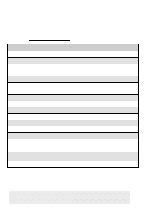
TABLE OF CONTENTS
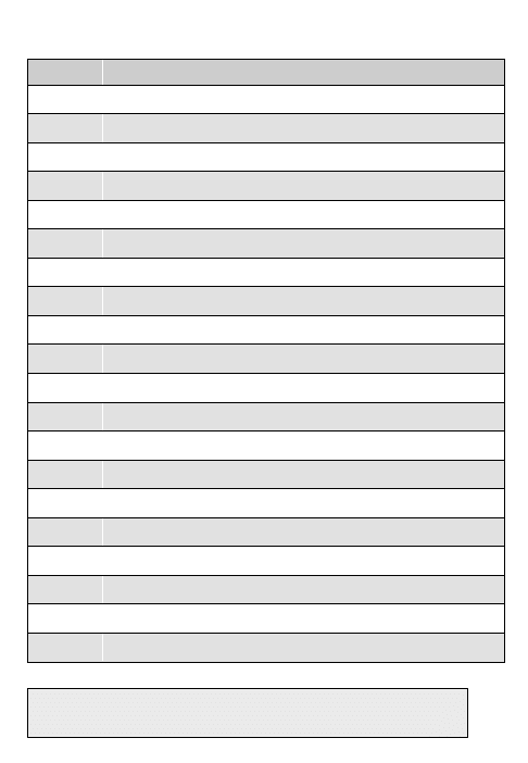
1
Table #
Table Title
Page #
1
KL-43 Recommended Settings
8
2
ViaSat Recommended Settings
9
3
5-kHz DAMA Checklist
13,14
4
5-kHz DAMA I/O Data Rates
14
5
Synchronous/Asynchronous Data Communications
18
6
5-kHz DAMA Hot Keys
22
7
Service Assigned Errors and Warnings
27
8
Message Queue Errors
27
9
5-kHz DAMA Messages
28-31
10
25-kHz DAMA Checklist
33,34
11
25-kHz DAMA I/O Data Rates
34
12
25-kHz DAMA Hot Keys
39
13
25-kHz DAMA Messages
43,44
14
Information Request Codes
45-51
15
Configuration Codes
52
16
Operational Status Messages
53
17
Frequency and Power Levels for LOS
55
18
Retransmit Single Channel and Frequency Hopping
58
19
25-kHz Satellite Channels
65,66
20
5-kHz Satellite Channels
67,68
LIST OF TABLES
INTRODUCTION

2
SCOPE This manual is a quick reference guide for trained users of Radio Set,
AN/PSC-5. Refer to TM 11-5820-1130-12&P for more detailed instructions.
WARRANTY This equipment is warranted by the manufacturer for three
years. See TB 11-5820-1130-30 for complete information.
WEB SITE PM-TRCS maintains a web site that contains the latest in technical
and reference information regarding the AN/PSC-5. The address is
http://www.monmouth.army.mil/peoc3s/trcs/mainfram.htm
. From this page
select Programs then on next page select Spitfire then on the next page
Technical Home Page link.
SECURITY INFORMATION The Receiver-Transmitter (RT) is a Controlled
Cryptographic Item (CCI). Handling of CCI equipment shall be in accordance
with DA PAM 25-380-2.
SAFETY Refer to TM 11-5820-1130-12&P for a complete list of safety
precautions related to this equipment.
HOW TO USE THIS MANUAL The following conventions apply throughout
this manual:
•
Each major topic (e.g., 5k-Hz DAMA, 25k-Hz DAMA) is formatted in
separate sections so they can be easily removed for convenience.
•
Lookup up the footnotes
{1}
in Appendix A for additional information.
•
In the electronic version of this TB, the Table of Contents, footnotes
{1}
and Table #s are hyperlinked throughout the document.
•
In the textboxes at the bottom of each page, the first line of darker text
indicates the topic on that page while the second line of lighter text
indicates the topic on the back of that page (if it is a new topic).
•
Use the following radio keys as identified to navigate the radios menu:
•
SELECT—Use the arrow keys to step through available selections or
use keypad to enter numeric value and press ENT.
•
ENTER—Enter is used to save the change made.
•
NEXT and PREV—Move through fields without making changes.
•
ESC (Escape) – Up to the next higher menu.
INTRODUCTION

3
The following procedure covers using the AN/CYZ-10 with CT3 Software to
load COMSEC variables. See TM 11-5820-1130-12&P for other devices.
NOTE: Do not connect fill device before power-up of radio set.
NOTE: If display shows the message “COMSEC Alarm," Press ENT or PTT
to clear the alarm.
NOTE: Position 6 contains the KEK or may be used for a TEK, if desired.
1. AN/CYZ-10 in platform Manual mode.
a. Turn on AN/CYZ-10.
b. Select XMIT and press ENT.
c. Select PLATFORM and press ENT.
d. Page-up or down to select your platform and press ENT.
e. Select MANUAL and press ENT.
f. Page-up or down to select equipment and press ENT.
g. Select MANUAL and press ENT.
h. Page-up or down to select Fill location and press ENT.
i. Page-up or down to select the Key and press ENT.
j. Connect fill cable from AN/CYZ-10 to AN/PSC-5 FILL connector.
k. Arrow down on AN/CYZ-10.
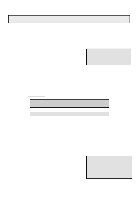
l. Set mode switch on AN/PSC-5 to F1 and press
ENT twice when directed then arrow down on
AN/CYZ-10.
COMSEC Randomize
Proceed to F1
Press ENT Twice
(0)
m. Select fill location on AN/PSC-5 then arrow
down on AN/CYZ-10.
n. Select key type on AN/PSC-5 then arrow
down on AN/CYZ-10.
F1: COMSEC
COMSEC Key: 1
Key Type: VINSN
o. Press ENT on AN/PSC-5 to initiate key fill and turn mode switch quickly to
F2 or CT and back to F1.
p. The AN/PSC-5 display will indicate “Key Filled." If “Key Fill Failure," check
equipment, then repeat steps a – o.
q. To load additional keys, repeat steps b – i, k and m – o.
LOAD COMSEC KEY(s)

4
2. AN/CYZ-10 in key management mode.
a. Turn on AN/CYZ-10.
b. Select XMIT and press ENT.
c. Select KEY and press ENT.
d. Page-up or down to select User Key and press ENT.
e. Select DONE and press ENT.
f. Select KYK-13 and press ENT.
g. Set mode switch on AN/PSC-5 to F1 and press ENT twice when directed.
h. Select fill location (1-6) on AN/PSC-5.
i. Select key type on AN/PSC-5.
j. Connect fill cable from AN/CYZ-10 to AN/PSC-5 FILL connector.
k. Arrow down on AN/CYZ-10.
l. Press ENT on AN/PSC-5 to initiate key fill and turn mode switch quickly to
F2 or CT and back to F1.
m. The AN/PSC-5 display will indicate “Key Filled." And the numbered
position where it is loaded. If “Key Fill Failure," check equipment, then
repeat steps a – l.
n. To load additional keys, repeat steps b – f, h, i, k and l.
3. AN/CYZ-10 in platform Automatic mode.
a. Turn on AN/CYZ-10.
b. Select XMIT and press ENT.
c. Select PLATFORM and press ENT.
d. Select SEL-PLT and press ENT.
e. Select AUTOMATIC and press ENT.
f. Connect fill cable from AN/CYZ-10 to AN/PSC-5 FILL connector then arrow
down on AN/CYZ-10.
g. Set mode switch on AN/PSC-5 to F1 then arrow down on AN/CYZ-10.
h. Select fill location (1-6) on AN/PSC-5 then arrow down on AN/CYZ-10.
i. Select key type on AN/PSC-5 then arrow down on AN/CYZ-10.
j. Press ENT on AN/PSC-5 to initiate key fill and turn mode switch quickly to
F2 or CT and back to F1.
k. The AN/PSC-5 display will indicate “Key Filled." If “Key Fill Failure," check
equipment, then repeat steps a – j.
l. To load additional keys, repeat steps b – e and h – j.
LOAD COMSEC KEY(s)
5
The following procedure covers using the AN/CYZ-10 with CT3 software to
load an orderwire key in position F2. See TM 11-5820-1130-12&P for other
devices.
NOTE: Do not connect fill device before power-up of radio set.
NOTE: If display shows the message “COMSEC Alarm," press ESC to clear
the message. Then press ENT or PTT to clear the alarm.
1. AN/CYZ-10 in platform Manual mode.
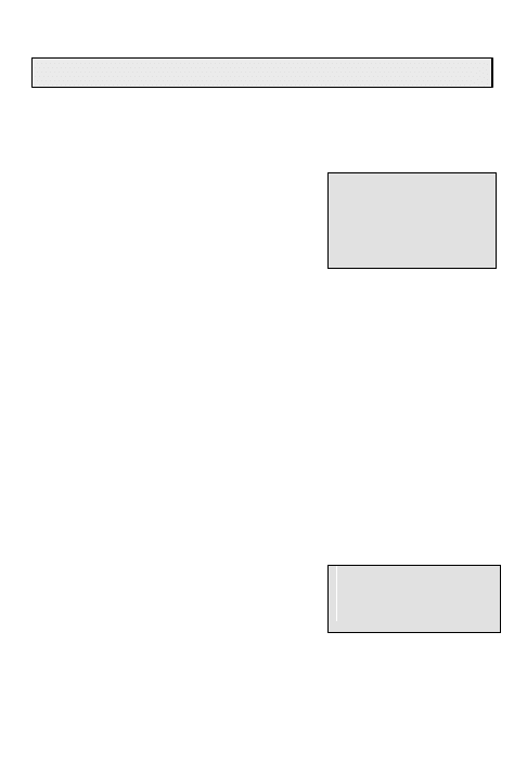
a. After loading COMSEC keys in F1 on
AN/PSC-5, set mode switch on AN/PSC-5 to F2
and AN/CYZ-10 will return to the select location
menu.
F2: FILL ORDERWIRE
KEYS: _________
LOAD: 1
b. Page-up or down to select Key and press ENT.
NOTE:
Orderwire Key #’s
Satellite Footprint
NCTAMS
1 and 2
CONUS & IO
LANT & NCTS GUAM
3 and 4
LANT and PAC
PAC and EURCENT
c. Select fill location (1-4) on AN/PSC-5.
d. Arrow down on AN/CYZ-10.
e. Press ENT on AN/PSC-5 to initiate key fill.
f. The AN/PSC-5 display will indicate “Key Filled." And the numbered position
where it is loaded. If “Key Fill Failure," check equipment, then repeat
steps b - e.
2. AN/CYZ-10 in key management mode.
a. After loading COMSEC keys in F1 on AN/PSC-5, set mode switch on
AN/PSC-5 to F2 and AN/CYZ-10 will return to the select location menu.
b. Select XMIT and press ENT.
c. Select KEY and press ENT.
LOAD ORDERWIRE KEY

6
d. Select DONE and press ENT.
e. Select KYK-13 and press ENT.
f. Select fill location (1-4) on AN/PSC-5.
g. Arrow down on the AN/CYZ-10
h. Press ENT on AN/PSC-5 to initiate key fill.
i. The AN/PSC-5 display will indicate “Key Filled." And the numbered position
where it is loaded. If “Key Fill Failure," check equipment, then repeat
steps b - h.
3. AN/CYZ-10 in platform Automatic mode.
a. After loading COMSEC keys in F1 on AN/PSC-5, the AN/CYZ-10 will
prompt to change the mode switch to F2 in order to load orderwire key.
b. Select fill location (1-4) on AN/PSC-5.
c. Press ENT on AN/PSC-5 to initiate key fill.
d. The AN/PSC-5 display will indicate “Key Filled." If “Key Fill Failure,"
check equipment, then repeat steps b and c.
Note: To check Orderwire Status, you must return to the F2 Position of the
mode switch to view the positions loaded.
LOAD ORDERWIRE KEY

7
The following procedure updates a key. A key update is irreversible.
NOTE: If the update count was exceeded the original key must be reloaded
and the update procedure must be repeated until the desire update number is
reached.
1. Set AN/PSC-5 to LOS operating mode (only necessary the first time).
2. Set mode switch to UPD.
3. ENTER the COMSEC key number to update
(1-5).
COMSEC KEY UPDATE
COMSEC Key: 1
Key Type: VINSN
Update 000
NOTE: Updates past 254 will cause a COMSEC alarm.
4. Carefully Press ENT. (Pressing too heavily on the ENT key may cause the
AN/PSC-5 to update more than once)
5. The display will indicate “Working."
6. The display will indicate “Updated." The update count will increment to
reflect how many times the ENT key was pressed which is not necessarily the
total key update.
7. Repeat steps 2 thru 6 as required.
8. To confirm COMSEC key update:
a. Set mode switch to CT.
b. Press ESC until the main menu is displayed.
c. Press 2. (Database Options)
d. Press 7. (COMSEC Key States)
e. Observe the key type and update count.
f. Press ESC when done to return to the main menu.
KEY UPDATE
CONNECT DATA DEVICES
8
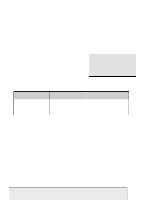
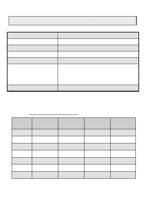
Use the following section to assist in configuring the KL-43 to interface with the
AN/PSC-5. Use the W1 cable between P2 of KL-43 to Aux Connector of
AN/PSC-5.
Table 1 KL-43 Recommended Settings
LOS
5-kHz
SATCOM
25-kHz
SATCOM
5-kHz
DAMA
Data Rate
9.6K
2400 digital
2400 digital
2400 digital
Data Rate*
16K
N/A
16K
N/A
*In Vinson mode using SL-3 cable in audio data mode.
CONNECT DATA DEVICES
9
Table 2 ViaSat Recommended Settings
(PDC ViaSat V-eMail with PDC-400
card via User provided cable between PDC card and Aux Connector of AN/PSC-5)
Recommended
Settings
LOS
Dedicated
DASA
5 kHz
DAMA
w/ADC
ON
5 kHz
DAMA
w/ADC
OFF
25 kHz
DAMA
w/ADC ON
25 kHz
DAMA
w/ADC
OFF
5 kHz
Message
Service
Communications Configuration (F7)
COM Port Baud Rate (External Data Controllers)
19200 all cases
Compression
ON
ON
N/A
ON
N/A
N/A
CSMA
ON
OFF
N/A
ON
N/A
N/A
Probe Retries
10
N/A
N/A
10
N/A
N/A
Channel Mode
Duplex
Duplex
N/A
Duplex
N/A
N/A
Burst Retries
10
10
N/A
10
N/A
N/A
FEC Code Rate
½
1
N/A
½
N/A
N/A
Adaptive
ON
ON
N/A
ON
N/A
N/A
Channel Access
Speed
Normal
N/A
N/A
Normal
N/A
N/A
Use ALE
OFF
OFF
N/A
OFF
N/A
N/A
Rekey After (x) Minutes
N/A all cases
Add'l ACK Delay
5
45
N/A
5
N/A
N/A
Turn Around Delay
2.5
2.5
N/A
2.5
N/A
N/A
Max Packets (Per
Burst)
256
256
N/A
256
N/A
N/A
TX Start Delay
0
0
N/A
0
N/A
N/A
TX End Delay
0
0
N/A
0
N/A
N/A
Direct Mode
Parameters
N/A
N/A
Default
Settings
N/A
Default
Settings
Default
Settings
ViaSat eMail Configuration (F8)
Network
ADC/PDC
DAMA
DAMA
DAMA
DAMA
DAMA
For small items,
prefer
N/A
Message
Message
Message
Message
Message
For large items,
prefer
N/A
Circuit
Circuit
Circuit
Circuit
Message
For reliable delivery
N/A
Circuit
Circuit
Circuit
Circuit
N/A
Reliable retry
method
ADC/PDC
ACKs
ADC/PDC
ACKs
Retries
ADC/PDC
ACKs
Retries
N/A
Reliable
Wait (x) seconds
for ACK from
recipient
N/A
N/A
60
N/A
60
N/A
Retry a maximum
of (X) times
N/A
N/A
100
N/A
10
N/A
Block Size (1K, 5K,
10K)
N/A
N/A
10K
N/A
1K
N/A
Timeouts
Pause (x) seconds between transmitting items
32 seconds all cases
Pause (x) seconds after receive before
transmitting
5 seconds all cases
Connections (F6)
Active Connection
N/A
Half-
Duplex
Half-
duplex
Half-
Duplex
Half-
duplex
Simplex
Use ADC Mode
N/A
ON
OFF
ON
OFF
OFF
CONNECT DATA DEVICES

10
Use the following procedure as an alternate method of obtaining ViaSat
Recommended Settings:
1. When first accessing, go to Setup and then User Mode. Select Expert.
2. Go to Setup and select "Select A Communications Driver." Select dts6.dll –
PDC Win95 driver, version 1.3 (or whatever version is available).
3. Go to Setup and select Presets. Select the option for the type of channel
being used. The options, taken directly from the menu, are indicated below
with their application to the AN/PSC-5 in parenthesis.
a. Line of Sight –Dedicated/Demand Assigned Single Access (DASA)
b. 25-kHz DAMA Circuit with ADC Mode On (use for 25-kHz DAMA)
c. 25-kHz DAMA Circuit with ADC Mode OFF (not used)
d. 5-kHz DAMA Circuit with ADC Mode ON (use for 5-kHz DAMA circuit
services)
e. 5-kHz DAMA Circuit with ADC Mode OFF (not used)
f. 5-kHz DAMA Message Service (use for 5-kHz DAMA when sending small
data messages less than 14k and selecting Message Queue on AN/PSC-5)
4. Go to Message and select Active Connections, except for Message
Service. Other than Message Service Highlight Broadcast and select
Half-Duplex Circuit then Apply. (Pressing the right arrow button on the
tool bar will also confirm this selection.)
For Message service Go to Setup and Select Expert Mode. Go to
Communications and ensure SIMPLEX is checked. Go to Active
Connections and select Message and address to be sent. Note: You
must go to Active Connections and select Message and address for each
Message service. Program automatically goes to No Active Connection
when Message is sent.
CONNECT DATA DEVICES
11
Perform the following to load terminal data.
NOTE: Current mode must be LOS to change the terminal address.
1. Press ESC until the main menu is displayed.
2. Press 2. (Database Options)
3. Press 3. (Terminal Data)
TERMINAL DATA
Address: #####
Backlight Timer: 10
Msg Release: MANUAL
NOTE: Once the Address is entered, ESC then enter back into Terminal Data
to check the address. Re-enter if required.
NOTE: Time is zeroed each time the terminal is powered down. Time is
required in ZULU only for passive ranging; otherwise it can be set as desired.
4. ENTER terminal address.
5. ENTER backlight timer shut-off timer delay (02-60 seconds).
6. SELECT 5-kHz message release option (MANUAL or AUTO).
{1}
7. SELECT latitude (N or S).
8. ENTER latitude in degrees (00-89) and
minutes (00-59).
9. SELECT longitude (E or W).
LAT: N ##:##
LON: E ###.##
Time: ##:##Z
Platform: STATIONARY
10. ENTER longitude in degrees (000-179) and minutes (00-59).
11. ENTER current time (ZULU) in hours (00-23) and minutes (00-59).
{2}
12. SELECT platform (Stationary or Mobile for airborne operations).
13. Press ESC when done to return to the Database menu.
TERMINAL DATA
SATELLITE EPHEMERIS

12
Perform the following to enter satellite ephemeris data, which is required for
passive ranging.
1. Press ESC until the main menu is displayed.
2. Press 2. (Database Options)
3. Press 5. (Sat. Ephemeris)
4. ENTER satellite ID number (1-8).
SATELLITE
EPHEMERIS
ID: 1
LON: E ###.##.##
Ascen Time: ##:##Z
5. SELECT longitude (E or W).
6. ENTER longitude in degrees (000-179), minutes (00-59), and seconds (00-
59).
7. ENTER Ascension time (ZULU) in hours (00-23) and minutes (00-59).
8. ENTER angle of inclination (00.0-10.0).
9. Press ESC when done to return to the
Database menu.
Inclination: ##.#
SATELLITE EPHEMERIS
13
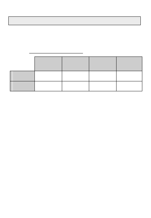
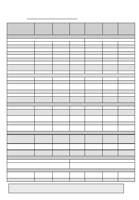
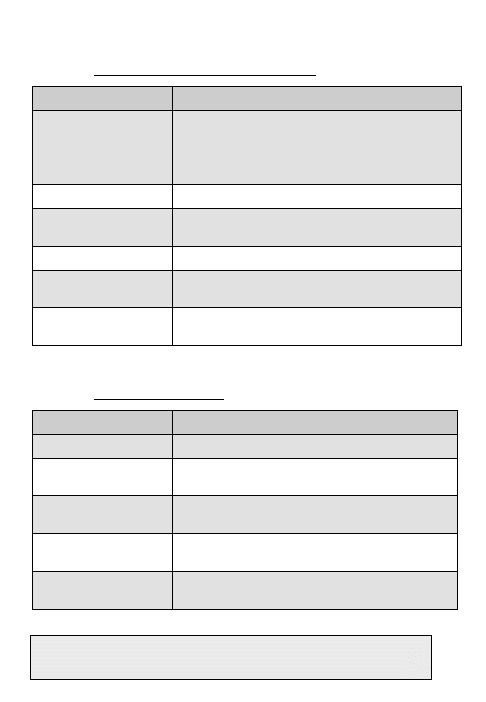
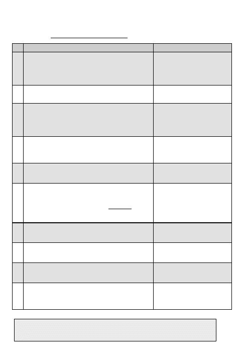
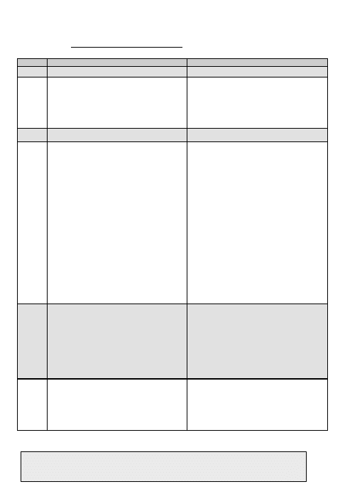
Use the list below as a reference of data required for 5-kHz DAMA. If you are
missing any of the information, contact your supervisor.
Table 3
5-kHz DAMA Checklist
ITEM
OPTIONS
Modulation
¨ PSK
Encryption
¨ ANDVT ¨ 3KG-84 ¨ 4KG-84 ¨ External
Mode
¨ V ¨ D
Data Rate
¨75 ¨300 ¨600 ¨1200 ¨2400 ¨9600 ¨16K
Transmit Power
{3}
23-43 dBm
Channel Number
________ (129-191,194-239)
Configuration Code
_______ (000-511 (use 060 for 2400bps))
Orderwire Encryption
{4}
¨ PT ¨ CT
Operation Mode
¨ Normal ¨ Silent ¨ EMCON
Ranging
{5}
¨ Passive ¨ Active ¨ (Maint)
Satellite ID
{6}
¨ 1 ¨ 2 ¨ 3 ¨ 4 ¨ 5 ¨ 6 ¨ 7 ¨ 8
Satellite Ephemeris
Longitude: ___
°
(0-180
°
)
Ascension Time: ___:__ Zulu
Inclination: ______
°
(0-10
°
)
Terminal Position
Latitude: N/S _____
°
(00-90
°
)
Longitude: E/W _____
°
(00-180
°
)
Terminal Time
{2}
__:__ Zulu
Terminal Address
{8}
_______ (00000-65535)
Platform
¨ Stationary ¨ Mobile
Message Release
{1}
¨ Manual ¨ Auto
5-kHz DAMA CHECKLIST
14
Guard List
{9}
1:____ 2:____ 3: ____ 4:____ 5:____ 6:_____
7: ____ 8:____ 9:____ 10:____ 11:____ 12:____
13:____ 14:____ 15:____
Demarcation Number
49999
COMSEC Key
¨ 1 ¨ 2 ¨ 3 ¨ 4 ¨ 5 ¨ 6
Orderwire Key
¨ 1 ¨ 2 ¨ 3 ¨ 4
LOGIN
{10}
¨ Pre-assigned ¨ Over the Air
Call Precedence
{11}
¨ FO ¨ F ¨ I ¨ P ¨ R
Destination
{12}
Five-digit address __________
Type Service
¨ DASA ¨ Circuit ¨ Message
Table 4
5-kHz DAMA I/O Data Rates
Baud
KG-84 Data
ANDVT Data
ANDVT Voice
75
X
X
300
X
X
600
X
X
1200
X
X
2400
X
X
X
9600
X
16k
X
5-kHz DAMA CHECKLIST
15
Perform the following to select 5-kHz I/O rates.
1. Press ESC until the main menu is displayed.
2. Press 2. (Database Options)
3. Press 4. (5-kHz I/O Rates)
4. Use NEXT/PREV to select a field.
5. Use arrow keys to select or deselect each
option then press ENT. If voice is used, 2400 will
be checked by default.
DAMA 5KHz I/O RATES
__75 __300 __600
__1200_
2400 __9600
__16k
6. Repeat steps 4 and 5 as required.
7. Press ESC when done to return to the Database menu.
5-kHz I/O RATES
Guard List

16
The guard list is a set of addresses for which a terminal receives services (do
not enter your terminal address). The guard number is the address of a single
terminal or network. Network addresses (common guard, private guard, or
subnet) must be placed in the guard list so the terminal will receive
communication for that address. Terminal Addresses may be placed in the
Guard List if communications directed to that address need to be received by
your terminal.
NOTE: Placing any terminal address in the Guard List is not recommended in
5-kHz DAMA. Placing a Terminal Address in the Guard List causes that
address to be logged in to the network by the control station. Ensure in 5-kHz
that Terminal Addresses placed in the Guard List are not being used by
another active terminal. The Demarcation Point divides addresses between
single terminals and networks. Addresses below the demarcation point (single
terminals) should usually be left off the guard list. To add to or change your
guard list, follow the procedure below.
1. Press ESC until the main menu is displayed.
2. Press 2. (Database Options)
3. Press 2. (Guard List)
4. SELECT desired action (Add, Delete Modify or View).
5. Perform the following as required:
a. ADD. ENTER address.
b. DELETE. Use NEXT/PREV to move to the
desired address. Press ENT.
c. MODIFY. Use NEXT/PREV to move to the
desired address. ENTER the new address.
GUARD LIST
VIEW
1 64000 ------ -----
4 ----- ------ -----
7 ----- ------ -----
10 ----- ------ -----
13 ----- ------ -----
d. VIEW. Use NEXT/PREV to scroll through the list.
6. Press ESC when done to return to the Database menu.
GUARD LIST

17
Perform the following procedure to enter a DAMA preset.
1. Press ESC until the main menu is displayed.
2. Press 3. (Set Presets)
3. Press 1. (Set Mode Presets)
4. SELECT DAMA.
5. ENTER Preset number (1-6).
SET PRESET
DAMA -P#
TEK# PSK ANDVT V2400
5 KHz Tpwr 35 dbm
NOTE: Modulation is not selectable
6. ENTER the COMSEC key number (1-5).
7. SELECT encryption type (ANDVT, 3KG-84, 4KG-84).
8. SELECT mode (V or D).
9. SELECT data rate (75-2400).
10. SELECT DAMA type (5-kHz).
11. ENTER/SELECT power level (23-43dBm).
12. ENTER channel number (129-239).
Corresponding frequencies are displayed on
the next line.
Channel Number: ###
R###.### T###.###
Code:## OW:CT
Normal Range: Active
13. ENTER configuration code.
14. SELECT orderwire encryption (PT or CT).
15. SELECT mode of operation (Normal, EMCON, Silent ).
16. SELECT ranging (Passive, Active, MAINT).
17. If passive ranging, ENTER satellite number (1-8).
18. For 5-kHz DAMA, SELECT login (Preassigned, Over the Air).
19. If Preassigned, SELECT precedence (FO,
F, I, P, R).
20. If Preassigned, ENTER demarcation
number 49999. If demarcation number is not
entered in preset, the radio will default to
16384.
Channel Number: ###
R###.### T###.###
Code:## OW:CT
Normal Range: Passive
Satellite ID: 4
Login: Preassigned
Prec:R Dmark:49999#
5-kHz DAMA SERVICE PRESET(s)
5-kHz DAMA MESSAGE SERVICE PRESET(s)
18
Perform the following procedure to enter a 5-kHz Service preset.
1. Press ESC until the main menu is displayed.
2. Press 3. (Set Presets)
3. Press 2. (5K Service)
4. ENTER preset number (01-20).
SET PRESET 5K P01
CIR EN SYN V2400
Prec:R D:#####
Code:###
5. SELECT type of service (CIR or DASA).
6. SELECT encryption (EN or UN).
7. SELECT data communications (SYN or ASYN). Use Synchronous unless
sending Asynchronous data in PT.
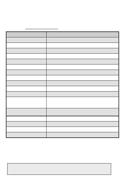
Table 5 SYN/ASYN
Data Device Type
Mode
Switch
Selection
Synchronous PT or CT SYN
Asynchronous
PT
ASYN
Asynchronous CT SYN
8. SELECT mode (V or D).
9. SELECT data rate (75-16k). For data, data rate must have been selected in
the 5-kHz I/O Rates menu.
10. SELECT precedence (FO, F, I, P, R).
{11}
11. ENTER destination address.
12. ENTER configuration code.
13. For DASA only, ENTER time requested in
hours and minutes or SELECT INDEFINITE.
Maximum time is 85 hrs 15 mins, in five-minute
increments. Indefinite is 85 hrs 15 mins.
SET PRESET 5K P01
DSA EN SYN V2400
Prec: R D:#####
Code:###
INDEFINITE
14. To load additional presets, repeat steps 4 thru 13.
5-kHz DAMA PRESET(s)

19
Perform the following to enter a 5-kHz Message preset.
1. Press ESC until the main menu is displayed.
2. Press 3. (Set Presets)
3. Press 4. (5K Message)
4. ENTER preset number (01-20).
SET PRESET 5K MESG
XMIT P01
TEK1 3KG84
PREC: R EN D:#####
5. ENTER the COMSEC key number (1-5).
6. SELECT encryption type (3KG-84, 4KG-84, ANDVT).
7. SELECT precedence (FO, F, I, P, R).
{11}
8. SELECT encryption (EN or UN).
9. ENTER destination address.
10. To load additional presets, repeat steps 4 thru 9.
5-kHz DAMA MESSAGE SERVICE PRESET(s)

20
This page intentionally left blank.

21
Perform the following to quickly start a 5-kHz DAMA network service.
1. SELECT DAMA.
2. ENTER preset (even if already displayed).
CURRENT MODE
DAMA -P1 - -060
TEK1 PSK ANDVT V2400
5KHz Tpwr 35 dbm
3. ENTER the service preset number (01-20)
NOTE: Verify your DAMA Address is
Correct before Continuing.
4. Press ENT on Start DAMA.
Channel Number: 136
R248.900 T302.500
Code: 060 OW:CT
Normal Range: Active
Login: Over The Air
Service Preset: 01
Start DAMA for 01000
5. Observe display. See Table 9 if LOGIN is
rejected by controller.
DAMA SQ - - 045
5K Acquiring N
SRV-Idle
1-Service Setup
Acquiring – Acquisition in process
Range – Wait while ranging in process
Login
−
Manual login required
Login-Pnd
−
Login pending
Connected
−
Login successful
6. At SrvcAsgnd popup message, ENTER on
ACCEPT. However if you wish to Reject the
Service, use the arrow keys to select REJECT
and press ENT key.
When a Warning or Error Message is
displayed refer to Table 7 for proper corrective
action.
SrvcAsgnd
CIR TEK ANDVT V2400
Prec:R EN D:01000
SYN S:02000 {ACCEPT}
7. SRV-RX/TX appears on the display and terminal is ready for normal
communications. See Table 6 for Hot Keys to access additional tasks.
QUICK START 5-kHz DAMA SERVICE
5-kHz DAMA HOT KEYS

22
Table 6 5-kHz DAMA Hot Keys
#
FUNCTION
1
Service Setup. Provides controller with
information on the type of service requested
in order to set up communication with
another party. Requests time on the satellite
for communication services, i.e., dials the
phone.
SERVICE SETUP P##
CIR EN SYN V2400
Prec: R D: #####
Code:###
{SEND}
2
Teardown. Ends current service although
the terminal remains logged into network,
i.e., hangs up the phone. (Hot key 1 in
DASA).
TEARDOWN 1/3
DESTIN ADD 02000 CIR
D PT PREC:R
LOCAL ACTIVE {SEND}
3
Service State. Indicates status of up to
three services.
SERVICE STATE 1/3
DESTIN ADD 02000 CIR
D PT PREC:R
LOCAL ACTIVE
4
Network State. Indicates status of current
network. LQ should be greater than 36.0
NETWORK STATE
PCC: ##### MHOP LIO
FOW miss ### LQ: ##.#
Prec Min/Max: R/FO
5
Status Messages. Displays last 10 stored
messages. (This is hot key 2 when using
dedicated service).
{13}
Msg ##:##Z 01 of 10
Network
Acquired
02
6 Logout. Removes terminal from network.
LOGOUT
Over the Air
{SEND}
7
Contention Ranging. Ranges satellite
when operating in silent mode. Contention
Ranging should be performed initially and
once every 4.5 hours thereafter.
CONTENTION
RANGING
{SEND}
8
Message Queue. Accesses queue to send
or receive data messages.
MESSAGE QUEUE
XMIT P## 1 IN QUE
TEK# ANDVT D2400
Prec:R EN D:#####
{SEND}
5-kHz DAMA HOT KEYS
23
Perform the following to manually setup a 5 kHz DAMA network.
1. SELECT DAMA.
2. ENTER preset (even if already
displayed).
CURRENT MODE
DAMA -P1 Sq- -045
TEK1 PSK ANDVT V2400
5KHz Tpwr 35 dbm
NOTE: For manual service setup, ensure service preset is set to 00.
3. Press ENT on Start DAMA.
Channel Number: 136
R248.900 T302.500
Code: 060 OW:CT
Normal Range: Active
Login: Over The Air
Service Preset: 00
Start DAMA for 01000
4. Observe display.
DAMA Sq- -045
5K Acquiring N
SRV-Idle
1
−−
Service Setup
Acquiring – Acquisition in process
Range – Wait while ranging in process
5. Resulting display.
DAMA Sq - - 045
5K LOGIN
SRV-Idle
LOGIN
6a. SELECT login type (Over the Air or
Preassigned).
LOGIN
Over The Air
{SEND}
6b. For Preassigned, SELECT
maximum assigned precedence (FO, F,
I, P, R) and ENTER demarcation
address (49999).
7. Press ENT on SEND.
LOGIN
Preassigned
Prec: R Dmark:#####
{SEND}
8. “Connected” appears on display and
terminal is ready for service setup. To
setup a service, proceed to manual
service setup by pressing Hot Key #1.
See Table 6 for Hot Keys to access
additional tasks.
DAMA Sq- -045
5K Connected N
SRV-Idle
1-Service Setup
MANUAL LOGIN TO 5-kHz DAMA
5-kHz DAMA CIRCUIT/DASA SERVICE SETUP
24
NOTE: Ensure current service state is idle (SRV-Idle).
Circuit/DASA Service Setup. Hot Key #1.
a. ENTER on preset number 00 for manual
service setup. Otherwise ENTER the service
preset number and proceed to step k.
b. SELECT type of service CIR or DSA.
SERVICE SETUP P##
DSA EN SYN V2400
Prec: R ANDVT D: #####
Code:### ##hr ##min
{SEND}
c. SELECT encryption (EN or UN).
d. If using data service, SELECT data type (SYN or ASYN).
e. SELECT mode (V or D).
f. SELECT data rate if applicable.
g. SELECT precedence (FO, F, I, P, R).
{11}
h. ENTER destination address.
i. ENTER configuration code if required.
j. If using DASA, specify length of service.
1. For INDEFINITE, press ENT on INDEFINITE and then press ENT on
SEND. (Actually INDEFINITE for DASA = 85 hrs 15 mins).
2. For timed service, with INDEFINITE highlighted press right or left
arrow key. With hr highlighted press ENT. Move cursor to ## field
and input number of hours, if applicable, and press ENT. Move
cursor to ## field and input number of minutes and press ENT.
k. Press ENT on SEND.
l. At SrvcAsgnd popup message, ENTER on
ACCEPT. However if you wish to Reject the
Service, use the arrow keys to select REJECT
and press ENT key.
Srvc Asgnd
DSA TEK1 KG-84 D2400
Prec: R UN D: 01320
SYN S:02000 {ACCEPT}
m. When a Warning or Error Message is displayed refer to Table 7 for proper
corrective action.
n. “SRV-Rx/Tx” appears on display, terminal is ready for communications.
5-kHz DAMA CIRCUIT/DASA
SERVICE SETUP

25
Send a Message. Hot Key #8.
a. Ensure service is idle. SELECT XMIT. The
display will indicate how many messages are in
the queue.
MESSAGE QUEUE
XMIT P## 0 IN QUE
TEK 1 4KG-84 D2400
Prec: R EN D:#####
{SEND}
b. ENTER 00 if not using a service preset. Otherwise, enter the preset
number and proceed to step h.
c. ENTER the COMSEC key (1-5).
d. SELECT encryption type (4KG-84, 3KG-84, VINSN, ANDVT) same as
Current Mode.
e. SELECT precedence (FO, F, I, P, R).
f. SELECT encryption (EN or UN).
g. ENTER address of party to whom you are sending the message.
h. Press ENT on SEND and observe display. See Table 8 if an error message
is displayed.
i. After “Enter Message Now” is displayed, key data device. Message input
from the data device will be confirmed by the message prompt “Msg Input
Done” briefly displayed on line 5 of the Msg Queue Display.
j. If sending a message to a terminal address with manual or automatic
release selected and the receiving operator downloads the message to their
data device within 60 seconds, two popup Acknowledgement messages will be
displayed. No acknowledgement is displayed if the message is sent to a
Network Address or if the message wasn’t downloaded to the data device
within 60 seconds.
NOTE: If using AUTO message release, messages are automatically sent to
the data device and the following procedure is not applicable.
Receive a Message. Hot Key #8
a. Ensure service is idle. SELECT RCV. The
display will indicate how many messages are in
the queue.
b. ENTER your COMSEC key number (1-5)
MESSAGE QUEUE
RCV 1 IN QUE
TEK 1 4KG-84 D2400
Prec: R EN D:#####
{RELEASE}
c. SELECT encryption type (3KG-84, 4KG-84, ANDVT) same as Current
Mode. See Table 8 if an error message is displayed.
d. SELECT RELEASE to send the message to the data device or DELETE to
erase the current message.
5-kHz DAMA MESSAGE SERVICE
5-kHz DAMA TEARDOWN AND LOGOUT
26
Teardown. Hot Key #2. Hot Key #1 for DASA.
a. SELECT service (# / #) to teardown.
b. VIEW DESTIN or SOURCE address. ENTER.
c. Press ENT on SEND.
TEARDOWN 1/1
DESTIN ADD 02000 CIR
D PT PREC:R
LOCAL ACTIVE
{SEND}
d. Press ENT to verify teardown. The display
will change to the network menu. A status
message will confirm the result of the teardown.
TEARDOWN
Verify Teardown
{SEND}
Logout. Hot Key #6. (See Note below)
a. SELECT Over the Air if you will be down for
30 minutes or longer. Select Force Locally if less
than 30 minutes.
LOGOUT
Over The Air
{SEND}
b. Press ENT on SEND. A status message will confirm the result of the
logout. If you forget to logout or if you are down for more than 30 minutes after
a Force Locally Logout, the JMINI will log you out of the network.
NOTE: When Logging out and back in later use the following as a rule of
thumb:
Logout Over the Air - Log back in Over the Air.
Logout Forced Locally – Log back in Preassigned
5-kHz DAMA TEARDOWN AND LOGOUT
27
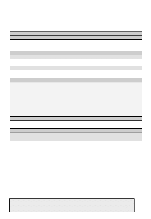
Table 7 Service Assigned Errors and Warnings
MESSAGE
ACTION
Verify I/O Device
a. ERROR. Attach asynchronous data device and
accept service.
b. WARNING. Attach synchronous data device
and accept service.
I/O Device Present?
Attach data device and accept service.
Check PT/CT Switch
Set mode switch to other setting (PT or CT) and
accept service.
Illegal Mode
Reject service.
Assuming Ext Encrypt
If using external encryption, accept service.
Otherwise reject service.
I/O Rate Invalid
Check for proper rate selection on the 5K DAMA
I/O Rates menu.
Table 8 Message Queue Errors
MESSAGE
ACTION
No Ext Dev ?
Attach data device.
Ext Encrypt ?
If using external encryption, continue. Otherwise,
set mode switch to CT and send encrypted data.
PT/CT ?
If message is not encrypted, set mode switch to
PT.
Sync Dev ?
Attach synchronous device or set mode switch to
PT.
Inv I/O Rate ?
Check for proper data rate selection on 5K DAMA
I/O rates menu.
5-kHz DAMA ERRORS AND WARNINGS
5-kHz DAMA MESSAGES

28
Table 9 5-kHz DAMA Messages
MESSAGE
ACTION
A
Acquisition
Failed
Your terminal is not receiving OW. Check azimuth, power out and
reposition antenna.
C Circuit
Aborted
Check previous status messages. If you were logged out, login
Over the Air. Other messages include circuit not available
(especially DASA) and the reason. Attempt to reestablish or
establish a different type of service.
Denied
(Reason)
Circuit service request has been denied for the stated reason. If
condition is correctable take appropriate action, or try again later.
Mismatch
Detected
An incoming service has been established but a mismatch has
been detected between the service and your current mode
settings. Check setting of PT/CT mode and type of attached data
device.
Preempted
The channel controller has preempted the circuit. Wait for it to
resume before transmitting any more messages. Or, you have
temporarily lost contact with the controller – wait for it to resume.
Receive Buffer
Overflow
Check data device for incomplete message or errors in message.
If needed, request source to retransmit message.
Setup Queued
(Reason)
Service is queued for the reason supplied. Local: terminal called
is logged in but time slot is not available.
MHOP – terminal called is not logged in with controller. If it is in
another footprint, wait. If it is supposed to be in your footprint,
teardown and try again later.
5-kHz DAMA MESSAGES
29
C Circuit
Setup Rejected
(Reason)
Service request is denied for the stated reason. Try again
later unless one of the reasons below is displayed.
Data rate. Requested a DASA service at higher than
2400 bps – no 25-kHz DASA channel available.
Not assignable. The LQ from your terminal or the
destination terminal is poor. Check your LQ. If LQ is low,
check your antenna or raise power.
Prec. Violation. The precedence entered is not allowed.
Check Network State menu for assigned values. Ensure
previous messages do not state Logged Out. If so, log back
in over the air and re-attempt service setup at lower
precedence.
Service Restrict. Request for a 2400 bps circuit denied
due to network traffic. Reduce data rate or wait until LIO no
longer displayed in Network State.
Terminated
(Reason)
An existing service has been terminated for the stated
reason. Try again later.
COMMAND
Rejected
Check parameters and network state. Try again.
Rejected Port is
busy (Check
Current Mode)
Your request is rejected because of an existing active
service. Ensure you are idle before setting up a service.
CTIC
Alarm Invalid key
Invalid OW key. Reload OW key in correct position.
Alarm Invalid TSN
Invalid time slot number detected. Reload OW key in correct
position.
Alarm Unknown
Cause
Reload OW key in correct position.
I
Incoming
Message
From:xxxxx
Aborted
Message from another terminal aborted.
5-kHz DAMA MESSAGES
30
L
Logged Out
(Reason)
The controller has logged your terminal off the network for the
reason supplied. Correct the error and perform an Over the
Air Login.
Invalid Address On Guard. Check the addresses in
your Guard List.
Not Authorized. Your Terminal Address is not in the
database – contact the controller if correcting it fails.
200 Missing FOWs. Once the terminal accumulates
200 FOWs the terminal automatically logs itself off. Check
antenna and radio. To clear count change Current Mode to
LOS and then return to DAMA. Start DAMA and perform a
Preassigned Login.
Invalid Service Request. The terminal is not logged into
the network. Login and resend the service request.
LOGIN
Command
Rejected
You have attempted to login more than once; wait for the
controller to respond.
Failed No PCC
Response
Try again. If you receive no response, the control station is
down. Contact control station.
Rejected, Invalid
Login Address
Your terminal address must be in the range of 1 to the
demarcation address (49999). Or, you have already logged
in; you were on a 25-kHz channel and are attempting to log in
on a 5-kHz channel; someone else has your terminal address
in their guard list; or you are trying to login Over-the-Air in
Silent/EMCON mode. To resume Login Preassigned.
Rejected, No
Capacity
The current channel has no capacity. Call the controller.
Rejected, Not
Authorized
Your terminal is not authorized to participate in the network.
Call the controller.
LOGOUT
Command
Rejected
You have attempted to logout more than once – wait the 18
seconds for response.
Failed No PCC
Response
The controller has not responded to your Logout request.
Shut down the system anyway.
MESSAGE
Aborted To:xxxx
(Reason)
Your message has been aborted for the stated reason. Try
again.
From:xxxx
Encrypt Mismatch
Detected
Your mode switch (PT/CT) setting is different than the
transmitting terminal. Contact distant end to correct.
5-kHz DAMA MESSAGES
31
MESSAGE
Input Rejected
Transmission rejected. Someone else is transmitting - try
again later. Or, radio is in idle – set up a service.
Output Rejected
Transmission rejected. Someone else is transmitting - try
again later. Or, radio is in idle – set up a service.
Setup Rejected,
(Reason)
Message setup is rejected for the stated reason.
Terminated
Frm:xxxx to:yyyy
(Reason)
Message is terminated for the stated reason. Try again
later.
Mode Command
Rejected, Node
Address is Zero
Your terminal address is entered as zero. This is reserved
for the controller. Enter a valid terminal address.
Msg Setup Rejected
Precedence
Violation
Precedence entered is not allowed. Check network state
menu for allowed values and re-enter.
No Resources for
Message From:xxxx
Your terminal is busy and cannot receive a message from
the other terminal.
R RANGING
Failed
Check current mode entries and antenna. Run BIT to
verify terminal operation.
Overdue Transmit
Inhibited
A successful ranging attempt has not been completed as
scheduled. Transmission is denied. Check antenna.
Transmit a ranging burst using the contention ranging
menu.
S SERVICE SETUP
Command Rejected
Verify you are connected and logged in and try again.
Rejected, Invalid
Data Rate
Ensure a valid data rate is selected.
T
Teardown Command
Rejected
The terminal has rejected your teardown request. Check
to see if you are Idle.
Transmission
Rejected Re-
Transmit
Transmission rejected. Someone else is transmitting - try
again later. Or, radio is in idle – set up a service.
Tx Rejected, Check
Mode & Status Msgs
Retransmit
Transmission rejected. Someone else is transmitting - try
again later. Or, radio is in idle – set up a service.
5-kHz DAMA MESSAGES

32
This page intentionally left blank.
33
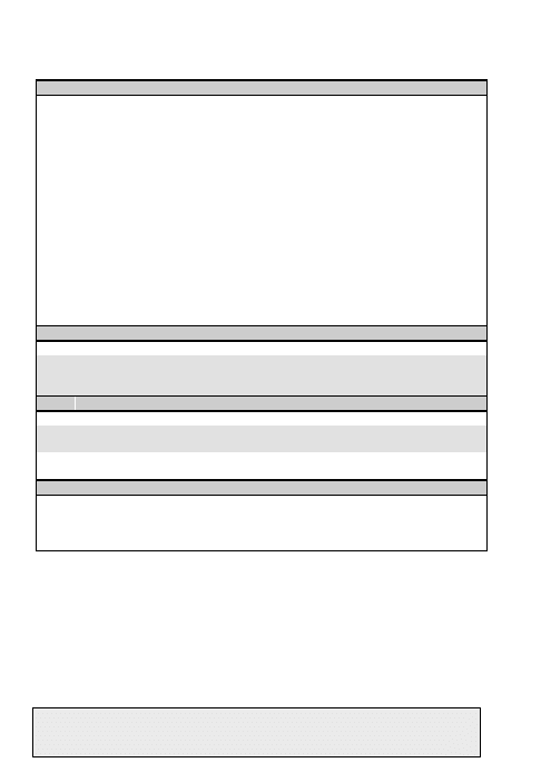
Use the list below as a reference of data required for 25-kHz DAMA. If you are
missing any of the information, contact your supervisor.
Table 10 25-kHz DAMA Checklist
ITEM
OPTIONS
Service Type
¨ AC ¨ DC
Modulation
¨ PSK
Encryption
¨ ANDVT ¨ 3KG-84 ¨ 4KG-84
¨ VINSON ¨ External
Mode
¨ V ¨ D
Data Rate
¨ 75 ¨ 300 ¨ 600 ¨ 1200
¨ 2400 ¨ 4800 ¨ 9600 ¨ 16K
Transmit Power
{3}
23-43 dBm
Channel Number
009-128, 192, 193 _________________
Configuration Code
01-99 (Must use Code assigned in SAA)
Orderwire Encryption
{4}
¨ PT ¨ CT
Operation Mode
¨ Normal ¨ EMCON
Ranging
{5}
¨ Active ¨ Passive ¨ (Maint)
Satellite ID
{6}
1-8
Satellite Ephemeris
Longitude: ___
°
(0-180
°
)
Ascension Time: ___:__ Zulu
Inclination: ______
°
(0-10
°
)
Terminal Position
Latitude: N/S _____
°
(00-90
°
)
Longitude: E/W _____
°
(00-180
°
)
Terminal Time
{2}
___:__ Zulu
25-kHz DAMA CHECKLIST
34
Terminal Address
{8}
________ (00000-65535)
Guard List
{9}
Up to fifteen five-digit addresses
COMSEC Key
1-6
Orderwire Key
1-4
Call Precedence
{11}
¨ EA ¨ FO ¨ F ¨ I ¨ P ¨ R
Destination
{12}
Five-digit addresses
__________ __________
__________ __________ __________
Circuit Number
000-999 (DC Mode only)
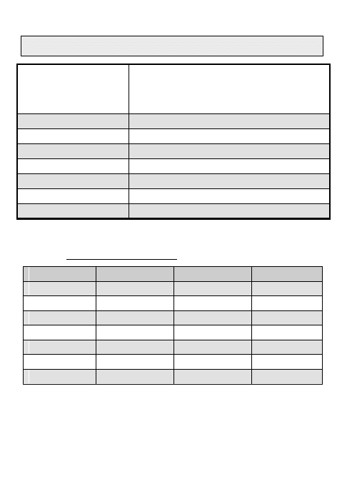
Table 11 25-kHz DAMA I/O Data Rates
Baud
KG-84 Data
ANDVT Data
ANDVT
Voice
VINSON
VOICE
75
X
X
300
X
X
600
X
X
1200
X
X
2400
X
X
X
4800
X
16K
X
X
16K not typically used due to limitation of DAMA Controller
25-kHz DAMA CHECKLIST

35
The guard list is a set of addresses for which a terminal receives services (do
not enter your terminal address). The guard number is the address of a single
terminal or network. Network addresses (common guard, private guard, or
subnet) must be placed in the guard list so the terminal will receive
communication for that address. Terminal Addresses may be placed in the
Guard List if communications directed to that address need to be received by
your terminal.
NOTE: Placing any terminal address in the Guard List is allowed in 25-kHz
DAMA (AC or DC). Placing a Terminal Address in the Guard List causes that
address to be logged in to the network by the control station. The
Demarcation Point divides addresses between single terminals and networks.
Addresses below the demarcation point (single terminals) should usually be left
off the guard list. To add to or change your guard list, follow the procedure
below.
1. Press ESC until the main menu is displayed.
2. Press 2. (Database Options)
3. Press 2. (Guard List)
4. SELECT desired action (Add, Delete Modify or View).
5. Perform the following as required:
a. ADD. ENTER address.
b. DELETE. Use NEXT/PREV to move to the
desired address. Press ENT.
c. MODIFY. Use NEXT/PREV to move to the
desired address. ENTER the new address.
GUARD LIST
VIEW
1 64000 ------ -----
4 ----- ------ -----
7 ----- ------ -----
10 ----- ------ -----
13 ----- ------ -----
d. VIEW. Use NEXT/PREV to scroll through the list.
6. Press ESC when done to return to the Database menu.
GUARD LIST
25-kHz DAMA PRESET(s)
36
Perform the following procedure to enter a DAMA preset.
1. Press ESC until the main menu is displayed.
2. Press 3. (Set Presets)
3. Press 1. (Set Mode Presets)
4. SELECT DAMA.
5. ENTER Preset number (1-6).
SET PRESET
DAMA -P#
TEK# PSK ANDVT V2400
25 KHz Tpwr 35 dbm
NOTE: Modulation is not selectable.
6. ENTER the COMSEC key number (1-5).
7. SELECT encryption type (ANDVT, VINSN, 3KG-84, 4KG-84).
8. SELECT mode (V or D).
9. SELECT data rate (75-16k) normally data rate is 2400bps ANDVT.
10. SELECT DAMA type (25 kHz).
11. ENTER/SELECT power level (23-43dBm).
12. ENTER channel number (009-128. 192,
193). Corresponding frequencies are displayed
on the next line.
Channel Number: ###
R###.### T###.###
Code:## OW:CT
Normal Range: Active
13. ENTER configuration code.
14. SELECT orderwire encryption (PT or CT).
15. SELECT mode of operation (Normal, EMCON).
16. SELECT ranging (Passive, Active, MAINT).
17. If passive ranging, ENTER satellite number (1-8).
18. For 25-kHz DAMA, SELECT Yes on Send
Status B unless EMCON.
19. To load additional presets, repeat steps 4
thru 18.
Channel Number: ###
R###.### T###.###
Code:## OW:CT
Normal Range: Active
Send Status B: Yes
25-kHz DAMA PRESET(s)
37
Perform the following to enter a 25-kHz AC Service preset.
1. Press ESC until the main menu is displayed.
2. Press 3. (Set Presets)
3. Press 3. (25K AC Service)
4. ENTER preset number (01-20).
SET PRESET 25K P01
Prec:R
#####, #####, #####
#####, #####, #####
5. SELECT precedence (EA, FO, F, I, P, R).
{11}
6. ENTER up to six terminal addresses (only one may be a network address).
When a network address is listed, only four additional terminal addresses (for a
total of five) may be entered.
7. ENTER 00-60 and SELECT timeframe (sec,
min, hrs, day) or press NEXT for indefinite (ind).
{14}
##min
8. To load additional presets, repeat steps 4 thru 7.
25-kHz DAMA SERVICE PRESET(s)
QUICK START 25-kHz DAMA SERVICE

38
Perform the following to quickly start a 25-kHz DAMA service.
1. SELECT DAMA.
2. ENTER preset (even if already displayed).
CURRENT MODE
DAMA P1 - -030
TEK1 PSK ANDVT V2400
25KHz Tpwr 35 dbm
3. ENTER the service preset number (01-20) if
not already loaded with above DAMA operating
preset.
4. Press ENT on Start DAMA.
Channel Number: 036
R267.050 T308.050
Code: 60 OW:CT
Normal Range: Active
Send Status B: YES
Service Preset: 00
Start DAMA for 01000
5
. Observe display. (M is always temporarily
displayed.)
Acquiring – Acquisition in process
{16}
Range – Wait while ranging in process
Connected
−
Send Status B successful
{15}
DAMA SQ- -134
25K AC Acquiring M
SRV-Idle
Send Status B
6. “Service Connected” appears on the display and terminal is ready for
normal communications. See Table 12 for Hot Keys to access additional
tasks.
QUICK START 25-kHz DAMA SERVICE
39
Table 12 25-kHz AC DAMA Hot Keys
#
FUNCTION
SCREEN
1
Service Setup. Provides controller with
information on the type of service requested in
order to set up communication with another
party.
SERVICE SETUP
Prec: R
#####, #####, #####,
#####, #####, #####
##min {SEND}
2
Teardown. Ends current service. (Hot Key 1
for DASA.)
TEARDOWN
{SEND}
3
Service State. Indicates status of current
service and displays up to 2 addresses of
connected parties. When connected to the
network, only the network addresses will be
displayed.
SERVICE STATE
SRV- Rx/Tx
02000, 01400
4
Network State. Indicates status of DAMA
Channel. (Not the terminal network.)
NETWORK STATE
Ctrl: Auto
CCOW miss ###
Prec Min: R FF:###
5
Status Messages. Displays last 10 stored
messages. (Hot key 2 for DASA.) {13}
Msg ##:##Z 01 of 10
Transmission
Enabled
6
Data Transfer. Used to send three-digit, user-
defined numeric codes between terminals.
DATA TRANFER
Prec: R
Party: ####
Data:
###, ###, ###, ###
{SEND}
7 Link Test. Performs a link test to the satellite.
LINK TEST
Rate: 9.6 kbps
{SEND}
8
Information Report. Sends information report
to channel controller.
INFORMATION REPORT
Report Code: #####
{SEND}
9 Paging. Pages other terminals.
PAGING
#####, #####, #####
{SEND}
0
Out of Service. Notifies controller of terminal
leaving DAMA Mode for specified time length.
Use Code 99.
OUT-OF-SERVICE
Prec: R
Reason: ## ## min
{SEND}
25-kHz AC DAMA HOT KEYS
25-kHz AC DAMA MANUAL SERVICE SETUP

40
Service Setup. Hot Key #1.
a. ENTER on preset number 00 for manual
service setup. Otherwise ENTER the service
preset number and proceed to step e.
SERVICE SETUP P00
Prec: R
#####, #####, #####,
#####, #####, #####
##min {SEND}
b. SELECT precedence (FO, F, I, P, R, EA).
c. ENTER addresses of terminals/network to be called.
d. To specify length of service ENTER requested length of connection (01-59),
then SELECT sec, min, hrs or day. Or to select indefinite time, use NEXT to
bypass “##," then SELECT ind.
{14}
e. Press ENT on SEND.
f. “Service Connected” appears on the display
and terminal is ready for normal
communications.
Msg ##:##Z 05of05
Service Connected
01
Check Terminal Status
Send a Status B whenever you desire to check if your radio is still connected.
a. Press ENT on SEND. A status message from
the controller, displayed as either a popup
message or stored in the terminal’s message
queue, will report the terminal’s status. The
display returns to the DAMA operations menu.
SEND STATUS B
{SEND}
25-kHz AC DAMA MANUAL SERVICE SETUP
41
Teardown. Hot Key #2. (Hot Key #1 for
DASA.)
a. Press ENT on SEND. The network menu will
indicate Idle when complete.
TEARDOWN
{SEND}
Data Transfer. Hot Key #6.
a. SELECT precedence (FO, F, I, P, R, EA).
b. ENTER address of destination terminal.
c. ENTER up to four three-digit groups (001-
255).
DATA TRANSFER
Prec: R
D: #####
Data:
###, ###, ###, ###
{SEND}
d. Press ENT on SEND.
{17}
e. The receiving terminal will observe the screen
at right. 000 will be displayed in unused groups.
MSG: 00:00Z
−−
of
−−
Data From: #####
###, ###, ###, ###
ROUTINE 01
Link Testing. Hot Key #7.
a. SELECT burst rate (9.6, 19.2, 32 kbps).
b. Press ENT on SEND. Wait for results. A
flashing M indicates test is running.
LINK TEST
Rate: 9.6 kbps
{SEND}
9.6 kbps
6-7 minutes
19.2 kbps
2 minutes
NOTE:
32 kbps
1 minute
Remember once the test is
initiated it can NOT be
stopped. However it does
NOT interfere with other
Communications.
c. Observe display. Symbol errors should be
less than 30 for data or 100 for voice. Missed
acquisitions should be 0. Note: Operationally it
is found that < 100 good for data & < 500 good
for Voice.
Msg 00:01Z
−−
of
−−
9.6 KBPS Link Test
Symbol Err: #####
Missed Acq ###
25-kHz AC DAMA
TEARDOWN, DATA TRANSFER AND LINK TEST
25-kHz AC DAMA
PAGING, INFO REQUESTS AND OUT OF SERVICE

42
Paging. Hot Key #9.
a. ENTER up to three terminal addresses to
page.
b. Press ENT on SEND.
{17}
PAGING
#####, #####, #####
{SEND}
c. The receiving terminal will observe the screen
at right.
MSG: 00:00Z
−−
of
−−
Call Waiting
Party: #####
Prec: Routine
Information Request Codes are two digit codes sent from the controller that
appear as pop up messages on your terminal. Information Report Codes are
your response to the request. These can be preprogrammed and stored in
your terminal database. If none are preprogrammed, 00001 will appear.
{18}
Receipt of Information Request Code
a. When an Information Request Code is
received check the code in your call directory (or
SOI).
b. Press ENT on SEND.
INFORMATION
REQUEST
Code: ##
Report Code: 00001
{SEND}
c. The display returns to the last active menu.
Information Report. Hot Key #8
a. ENTER the report code.
{18}
b. Press ENT on SEND.
INFORMATION REPORT
Report Code: 00001
{SEND}
Out of Service. Hot Key #0.
a. SELECT precedence (FO, F, I, P, R, EA).
b. User Reason Code 99.
OUT-OF-SERVICE
Prec: R
Reason: 00 ## min
{SEND}
c. ENTER 01-59 and then SELECT sec, min, hrs, day or ind.
d. Press ENT on SEND.
25-kHz AC DAMA
PAGING, INFO REQUESTS AND OUT OF SERVICE
43
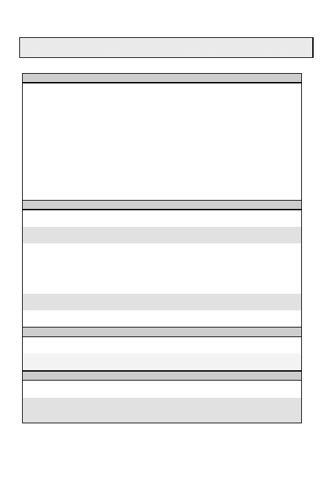
Table 13 25-kHz DAMA Messages
MESSAGE
ACTION
C
Call Waiting Party: #### Prec
Routine
You have been paged – notify the sender that you
received the page. Teardown from a current service
if you wish to talk to the sender.
CTIC
Alarm Invalid Key
Invalid OW key. Reload OW key in correct position
Alarm Invalid TSN
Invalid time slot number detected. Reload OW key
in correct position.
Alarm Unknown Cause
Invalid OW key. Reload OW key in correct position.
Alarm Zeroized by Controller
The controller has zeroized your keys. Reload the
new OW key in the correct position.
D
Data Transfer Request
(Result)
Displays result of data transfer request. No action
required unless noted below.
Denied. Request to transmit is denied because
you are in EMCON mode.
Destination Busy. Try again later
Destination Out of Service. Try again later.
Not Acknowledged. The controller has not
acknowledged your request. Check antenna and re-
send request.
L
Link Test Request (Result)
Displays result of link test request. Denied Link
Tests are identified by an Information Request Code.
O
Orderwire Zeroize Notification
The controller has zeroized all your orderwire
encryption keys. Reload keys.
Out of Service Request
(Result)
Displays result of request to suspend temporarily
service. Turn off radio or exit 25-kHz DAMA no
matter which message is received.
25-kHz DAMA MESSAGES
44
P
Paging Request (Result)
Displays result of request to suspend temporarily
service. No action required unless noted below.
Denied. Request to transmit is denied because
you are in EMCON mode.
Designation Busy. Try again later
Destination Out of Service. Try again later.
Not Acknowledged. The controller has not
acknowledged your request. Check antenna and re-
send request.
R
Requested Party Busy
Destination is busy. Try again later
S
Satellite Ranging Failed
Ranging attempt has failed. Terminal will
automatically attempt again. If ranging continues to
fail, check antenna and power setting.
Service Request Denied
Your request for service is denied. You are either in
EMCON mode or your precedence is not valid.
Status Report Request
(Result)
Displays result of a Send Status B. No action
required unless noted below.
Denied. Request to transmit is denied because
you are in EMCON mode or a status report is
pending.
Destination Busy. Try again later
Destination Out of Service. Try again later.
Not Acknowledged. The controller has not
acknowledged your request. Check antenna and re-
send request.
T
Transmission Inhibited
The controller has stopped all transmissions on the
channel. Wait until “Transmission Enabled” is
displayed.
Transmit Aborted Due to
Constant Key Alarm
The handset PTT or data device RTS has been
active for over 17 minutes and the controller has
commanded your terminal to stop transmitting.
Release PTT or deactivate RTS. Check the Guard
List since the Controller likely deleted your Network
addresses. Re-enter as applicable and then setup
service once again.
Tx Rejected, Check Mode &
Status Msgs Retransmit
Transmission rejected. Someone else is transmitting
- try again later. Or, radio is in idle – set up a service.
25-kHz DAMA MESSAGES
45
Table 14 Information Request Codes Please note: wherever it states
contact the NCTAMS – the RSSCs may be contacted and can provide you assistance!
Code Condition
Action
1-3
***Unused***
NONE
4
Disconnect constant key offender.
The controller has determined that a constant
key offender should be disconnected.
You have been transmitting for 17 minutes –
waveform does not allow for constant
transmission. AN/PSC-5 terminal does not
provide a means to bypass this so all
transmissions must be less than 17
consecutive minutes.
5-65
***Unused***
NONE
66
Your terminal type cannot be connected
to the requested guard number.
The requested guard number is associated
with terminals built to a different version of
the MIL-STD. Check the guard number and
try again.
1. FSCS or 183A terminal requested
to connect to a guard number
associated with 183 (baseline)
terminals
2. 183 (baseline) terminal requested
to connect to a guard number
associated with FSCS and 183A
terminals
Information Request Code 66 is sent when
user requests to join/start a network service
using the "wrong" network address.
MIL STD 188-183(-) uses the Odd numbered
(primary) address; this is the AN/PCS-5,
AN/PRC-117F, etc.
FSCS & MIL STD 188-183(A) use the Even
numbered (alternate = primary+ 1), this is the
TD-1271 only for now as there are not any
188-183(A) terminals yet certified.
The new DAMA SAC channel controller
software links this even/odd network address
pair to maintain interoperability between all
the terminal types.
Example VOICE CMD NET:
Primary network address: 56001 for MIL STD
188-183(-); alternate network address: 56002
for TD-1271. The DAMA SAC links 56001 &
56002 in its software to the same data slot.
You would need to use 56001 in the
AN/PSC-5.
67
Your terminal cannot communicate on the
assigned channel.
The requested service is assigned on a
channel a MIL-STD-188-183 (baseline)
terminal cannot be connected to
•
The channel is identified by an 8-bit
channel code and this terminal can
only use channels identified by a 6-bit
channel code
•
The channel is a 5-kHz slave channel
AN/PSC-5 terminals would receive this code
if mistakenly assigned a 5-kHz slave channel.
AN/PSC-5 terminals cannot utilize these
channels. Contact NCTAMS if you receive
this message.
68
Log Out report has been ignored –
Terminal log out can only be performed from
port 1.
The Log Out Information Report was sent
from a port other than port 1. Change to port
1 and retry.
Should not receive this code – contact
NCTAMS if you do. AN/PSC-5 is a single
port terminal and therefore only uses port 1.
In addition, start using code 99 when sending
the out of service message. This will actually
perform logout on the DAMA SAC.
INFORMATION REQUEST CODES

46
69
Terminal ID duplicates an existing
operational address.
The requesting terminal’s ID duplicates the
address of an operational controller.
Your terminal address is the same as a
PCC's. Check your terminal address!
70
Requesting party’s guard list does not
contain guard address.
The requesting user’s port guard list does not
contain the guard address of the guard it is
trying to activate with the current request.
Put the correct Net Guard Address in the
Guard list.
71
Service Request Access Restriction
Violation.
The service request either has a higher
precedence than is allowed by the source’s
terminal access restriction level or it has a
lower precedence than the channel access
restriction level.
Send a Status B Message. Lower your
precedence and re-setup the service.
72
Requesting party already has an
outstanding queued request.
Only one request at a time may be queued
from a user. This user already has a request
queued and thus, the current request is being
canceled.
Three things may have occurred – one you
have already sent a service set up that was
queued. Only one service of any kind on 25-
kHz DAMA so you must teardown and then
set up the new service. Two – the control
station believes you have a service pending.
Teardown and try again. If this does not
work, teardown, Out-of-Service, Send Status
B, then set up the service again. Third - You
just received a busy signal from the distant
end – try again later or page the terminal
address so they know you are trying to
contact them. (This one doesn't make sense
but has happened on occasion.)
73
Requesting party is not authorized to
activate All-Call.
The current request is being canceled
because only the controller operator may
activate a service to the All-Call address.
This code only applies if you set up the
service to addresses: 16383 or 65535.
Check the service setup and ensure correct
address is entered – send request again with
correct address. If still receiving 73 – JMINI
has address identified incorrectly – contact
NCTAMS.
INFORMATION REQUEST CODES

47
74
Requested terminal is already connected
to a DASA service.
The requested user is on a terminal that is
already connected to a DASA service, and
thus, is unavailable.
The terminal you are calling is unavailable.
Teardown (if required) and try again later.
75
Request canceled by user.
The source of the service request has now
canceled that request while it was queued
waiting for a resource.
You will receive this anytime you teardown
the service before it is provided (after
sending a service set up, usually queued) –
no action required.
76
Queued call canceled; service queue
time-out timer expired.
The previously queued request from the
requesting user has been canceled due to
the controller imposed time-out limit on
queued service requests.
JMINI canceled your service – set up the
service again.
77
Your terminal does not exist in the
controller database.
The controller has no record of the
requesting terminal’s address having been
assigned.
Your terminal address is missing from the
database – check your address to ensure it is
correct. If correct, contact the NCTAMS.
78
Request queue is currently full.
The controller has too many requests in
queue and cannot accept any more at this
time.
Should not normally see; however, you just
received a busy signal again – try again later.
79
Queued call canceled; connection is no
longer possible.
The controller has deleted a request from
queue, either at the request of the controller
operator or because it is no longer a valid
request.
Attempt the service setup again. If the
terminal(s) you called sent an out of service
or you are the only one up on the network,
you may receive a different code providing
updated information.
INFORMATION REQUEST CODES

48
80
Enter a Configuration Code and try again.
The terminal operator has not entered a
Configuration Code into the port originating
the request since the terminal was powered
up or since an RCCOW: Out-of-Service
message was sent from this port.
Check the configuration code, ensuring there
is one and it is correct, in the current menu
then set up the service again.
81
Required data rate can’t be supported.
The data rate required for this connection is
not supported by any of the channels
operating on this satellite.
You requested a different data rate than the
original submitted in the SAR. The channel
cannot support changing to allow you to use
a different data rate. Set up service at
original data rate and configuration code (via
current mode screen).
82
Requested party unknown. Check Call
Directory and try again.
The requested user or guard doesn’t exist in
the controller database.
Check the terminal or network address in the
service set up then try again. If network
address is correct and terminals are up in the
network, the controller may not have
activated the network address – contact the
NCTAMS. (If unable to contact NCTAMS, try
making a conference call.)
83
Cannot add users to this guard.
The requesting party is already connected to
a guard and has attempted to add user
port(s) to the guard connection.
You are not at SVC Idle – teardown then
retry your call. (Even if it says SVC Idle, do
this first!)
84
Cannot add a guard to your existing call.
The requesting user is already participating
in a call and has attempted to add a guard to
this pre-existing connection.
You are not at SVC Idle – teardown then
retry your call. (Even if it says SVC Idle, do
this first!)
85
Requesting party is not authorized to
activate this guard.
The requesting user has attempted to
activate a guard, but this user is not author-
ized to activate the guard for one of the
following reasons:
•
The requesting party has attempted
to activate a Private Guard, but is
not a Net Controller for this guard
(All)
The JMINI database has the Net Guard
Address marked wrong – need to contact the
NCTAMS to correct this.
OR
You asked for a Private Guard and the NCS
has not or is not setting up the service to the
network first.
86
Requesting party is not a member of this
Private Guard.
The requesting user has attempted to join a
Private Guard, but this user is not an
authorized member of this Private Guard.
You were not listed as part of the Private
Network OR you are calling the wrong Net
Guard Address (check your service setup). If
you were supposed to be part of the Private
Network, contact the NCTAMS.
INFORMATION REQUEST CODES

49
87
Requested party’s terminal is
unauthorized or zeroized.
The requested user is on a terminal that is
marked in the controller database as in an
unauthorized or zeroized state.
Check to ensure you called the correct
address. If yes, contact the NCTAMS about
the address to find out why it is marked this
way. JMINI Controller sends.
87
5/25-kHz Slave Channel is not available
from requestor’s home channel
Requested service requires a 5-kHz or 25-
kHz slave channel, but the required slave
channel is not accessible from the
requestor’s home channel.
You requested a service with a terminal
and/or network address assigned to a
different home channel. Currently, no
capability to assign you to either a different
home channel or a slave channel associated
with a different home channel. If authorized
to talk within this network, check current
mode screen to ensure it is set up for the
correct home channel. If not, send an out of
service, make changes or select correct
preset, reenter the DAMA mode on the
correct channel and set up your service
again. DAMA SAC sends.
88
Requesting party’s device is not
compatible with this guard.
The requesting port’s baseband device is not
compatible with the baseband device
specified for this guard.
Your configuration code does not match what
is in the JMINI database for the Net Guard
Address. Check the code – if correct per the
SAA, try again. If continued receipt of info
code - contact the NCTAMS.
89
Requested party has no compatible
baseband device.
No port on the requested terminal is
configured for a baseband device compatible
with the baseband port originating the
request.
Your configuration code does not match what
is in the JMINI database for the terminal
being called. Check the code – if correct the
distant end may have entered the wrong
code. Try again first then need to work with
distant end (maybe use Data Transfer??).
90
None of the users requested is available.
Not enough requested users are capable and
available (for various reasons) to activate the
service request.
You need to try and set up the service again
later. If making a conference call, page the
other terminals. If a network call, no one else
is up but your terminal.
91
Connection would cause contention.
The requested connection would cause
contention with an ongoing communication.
Do a Teardown and Out Of Service then
Send Status B and attempt to set up the
service again. If this does not work, contact
the NCTAMS. The JMINI mistakenly has you
already in a service.
INFORMATION REQUEST CODES

50
92
Not all requested parties could be
connected.
At least one, but not all, of the requested
parties could be connected. (This request is
honored, connecting all available parties.)
You set up a conference call and not all
received the service assigned message. Call
all the stations and find out who isn't there
that you called. Prior to making a conference
call, it is highly suggested you page everyone
to ensure they are up before you make the
call. This should ensure you do not receive
this message. However, if you do, the
terminal that did not receive the message
needs to send a Status B Message. (maybe
use Data Transfer to assist? Only way to get
any missed terminals into the service is to all
teardown, then one terminal set up the
service again.
93
Other Link Test in progress.
Only one link test at a time can be conducted
on a channel and another user terminal is
conducting one at this time.
Wait a couple minutes and rerun your link
test. Be sure to run it at 32 ksps first!
94
Unable to connect parties from different
channels (JMINI sends) OR
Unable to perform frequency switching
required for this connection (DAMA SAC
sends)
Frequency switching is required in order to
connect the requested service, but frequency
switching cannot be accomplished for any of
the following reasons:
•
Terminal or terminals that must switch
are not capable of doing so;
•
Communications and orderwire
channels are not on the same satellite;
•
Communications and orderwire
channels are not controlled by the
same controller;
•
Required frame segment on the
communications and orderwire
channels don't match;
•
Frame timing for the channels
may not be aligned,
You requested a service with a terminal
and/or network address assigned to a
different home channel. Currently, no
capability to assign you to a different home
channel If authorized to talk within this
network, check current mode screen to
ensure it is set up for the correct home
channel. If not, send an out of service, make
changes or select correct preset, reenter the
DAMA mode on the correct channel and set
up your service again.
95
Demand Assigned Activation disabled for
this guard.
This network can only be activated on a pre-
assigned basis. In order for a user to be able
to activate this network, the NMS operator
must check the "Allow User to Activate" box
in the network definition.
The JMINI database has the Net Guard
Address marked wrong – need to contact the
NCTAMS to correct this.
INFORMATION REQUEST CODES

51
95
DASA requests are reserved for guards
only.
The requesting user’s Configuration Code
indicates a DASA service and the user has
requested connection to another user or
users. Configuration Codes 98 and 99 are
reserved for DASA services and only Private
Guards can be assigned to DASA channels.
Should not receive this code – contact
NCTAMS if you do. Currently, there are no
procedures to request DASA from 25-kHz
DAMA!
96
No DASA channel available.
Should not receive this code – contact
NCTAMS if you do. Currently, there are no
procedures to request DASA from 25-kHz
DAMA!
97
Party is already connected to a DAMA
time slot.
Can’t assign a DASA connection if another
user port on the requested/requesting user’s
terminal is participating in a DAMA service of
equal or higher precedence. If it were of
lower precedence, that user could have been
preempted out of the DAMA service.
Should not receive this code – contact
NCTAMS if you do. Currently, there are no
procedures to request DASA from 25-kHz
DAMA!
98
Too many guards specified in this
request.
More than one guard was specified in
conference request.
You can only have ONE network address in
the request. Use terminal addresses for the
other four addresses.
99
Reserved for TD-1271 Home Channel
Change notification.
Should not receive this code – contact
NCTAMS if you do.
INFORMATION REQUEST CODES
CONFIGURATION AND INFO REPORT CODES
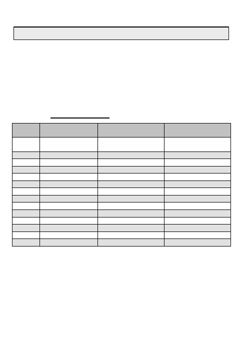
52
CONFIGURATION CODES
Configuration codes identify to the control station the baseband equipment
attached to the terminal I/O port. Currently, the codes for 5 and 25-kHz DAMA
are the same, except the 5-kHz codes are prefaced with a zero (i.e., they are
three digits not two). Use the code provided by the NCTAMS if available (must
have for 25-kHz DAMA). The codes listed below are for 2400 bps.
Table 15. Configuration Codes
Code
#
Equipment
Protocol
Crypto
60
Network
(Prearranged)
IAW
Network/prearranged)
IAW
Network/prearranged)
61
FAX
FAX
KYV-5, KY-99A/100
62
FAX
FAX
KG-84A/C
63
Handset/ANDVT
Voice
KYV-5, KY-99A/100
64
Data/ANDVT
Prearranged
Prearranged
66
PSC-2A
PSC-2A
KG-84A/C
67
PSC-2A
PSC-2A
KYV-5, KY-99A/100
68
KL-43C/F
ASCII 8N2
KL-43C/F
69
Computer
ASCII 8N2
KG-84A/C
70
Computer
ASCII 8N2
KYV-5, KY-99A/100
71
Tactical Internet
Tactical Internet
KG-84A/C
72
PC
Prearranged
KG-84A/C
98
DASA 5KHz
Prearranged
Prearranged
99
DASA 25KHz
Prearranged
Prearranged
INFORMATION REPORT CODES
Information Report Codes are currently not defined, but will be placed in the
call directory when available.
CONFIGURATION AND INFO REPORT CODES
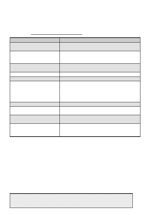
53
The following tables list some of the status messages that may be displayed
during DAMA operation. See TM 11-5820-1130-12&P for a complete listing.
Table 16 Operational Status Messages
MESSAGE
ACTION
Alarm Detected Press
Enter or PTT to Clear
Press ENT or PTT. If it persists, load
variables.
Batteries Depleted
Operation Suspended
Replace Batteries
Radio Set can no longer transmit/receive.
Operation suspended.
Cannot Change
Parameters While in Tx
You cannot change parameters while
transmitting. Wait until terminal is idle.
COMSEC fault
Notify unit maintenance.
High TX Current
Notify unit maintenance.
Invalid Combination
Parameters Modified To
Match Mode
Your entered parameters were invalid and
have been changed to valid parameters.
Also, you are in PT and the parameters were
set for CT. Changes were made. Preset
displays M# instead of P#.
Modem failure
Notify unit maintenance.
Modem is still initializing
Mode not changed
Wait until initialization is complete to change
mode.
Power Regulator fault
detected
Notify unit maintenance.
Tx Rejected, Check Mode
& Status Msgs Retransmit
Transmission rejected. Someone else is
transmitting - try again later. Or, radio is in idle
– set up a service.
OPERATIONAL STATUS MESSAGES
LOS PRESET(s) AND OPERATION

54
This page intentionally left blank.
55
Perform the following procedure to enter Line of Sight (LOS) preset(s).
1. Press ESC until the main menu is displayed.
2. Press 3. (Set Presets)
3. Press 1. (Set Mode Presets)
4. SELECT LOS.
5. ENTER the preset number (1-6).
SET PRESET
LOS -P#
TEK# FM VINSN V16K
Normal Tpwr 30 dbm
R###.### T###.###
6. ENTER the COMSEC key number (1-5).
7. SELECT modulation (AM, FM or FSK).
8. SELECT encryption type (VINSN, FASCN, 3KG-84. 4KG-84).
9. SELECT mode (V or D).
10. SELECT data rate.
11. In PT mode only, SELECT Normal.
12. SELECT transmit power level.
13. ENTER receive frequency (030.000-399.975)
Table 17 Frequency And Power Levels
30.000 – 87.975
FM/FSK
23-43 dbm
108.000 – 129.975 AM 23-38 dbm
130.000 – 148.975
AM/FM/FSK
23-38 AM/23-39 FM/FSK
156.000 – 173.975,
225.000 – 399.975
FM/FSK 23-39 dbm
14. If the transmit frequency is the same as the receive frequency, press ENT.
Otherwise ENTER a new transmit frequency.
15. To load additional presets, repeat steps 4 thru 14.
Perform the following procedure for Line of Sight (LOS) operation.
1. SELECT LOS.
2. ENTER the preset number (1-6).
3. Check all fields to ensure they are correct.
{19}
CURRENT MODE
LOS -P# Sq- -054
TEK# FM VINSN D16K
Normal Tpwr 37 dbm
4. Proceed with communications.
LOS PRESET(s) AND OPERATION
SATCOM PRESET(s) AND OPERATION

56
Perform the following procedure to enter a SATCOM preset(s).
1. Press ESC until the main menu is displayed.
2. ENTER 3. (Set Presets)
3. ENTER 1. (Set Mode Presets)
4. SELECT SATCOM.
5. ENTER the preset number (1-6).
NOTE: Modulation is not selectable.
Satellite loopback is not performed in FSK.
SET PRESET
SATCOM -P#
TEK# FSK VINSN V16K
Normal Tpwr 43 dbm
6. ENTER COMSEC key (1-5).
7. SELECT encryption type (ANDVT, VINSN, 3KG-84, 4KG-84).
8. SELECT mode (V or D).
9. SELECT data rate (1200, 2400, 9600, 16k bps).
10. ENTER/SELECT power level (23-43dbm).
NOTE: It may be necessary to reenter the encryption type and data rate after
entering the channel number.
11. ENTER channel number (009-239) or 999
to manually enter frequency pairs. It is
recommended to use the home Channel
Number. SATCOM loopback cannot be
utilized if 999 is the Channel Number.
Channel Number: ###
R###.### T###.###
DIFF
12. If 999 was entered in previous step, then ENTER the receive and transmit
frequencies (225.000-399.995).
13. SELECT encoding type (DIFF or NDIFF). Radios must have the same
Encoding Type in order to communicate.
14. To load additional presets, repeat steps 4 thru 13.
Perform the following procedures for SATCOM operation.
1. SELECT SATCOM.
2. ENTER the preset number (1-6).
3. Check all fields to ensure they are
correct.
{19}
CURRENT MODE
SATCOM -P# Sq-__-030
TEK# FSK VINSN V16K
Normal Tpwr 43 dbm
4. Proceed with communications.
SATCOM PRESET(s) AND OPERATION
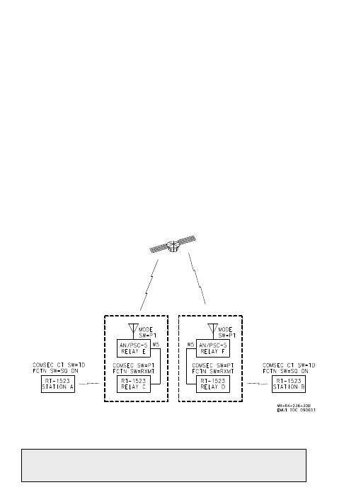
57
Perform the following procedure to set up a satellite relay using AN/PSC-5 and
SINCGARS radio sets.
Retransmission may use analog voice (LOS only) or 16 kbps digital (voice or
data) signals using LOS, SATCOM or 25kHz DAMA. Encryption is supplied by
the source and destination radios.
1. Configure radios for over the air communications. Since the AN/PSC-5 is
used to retransmit and not initiate communications, it is not necessary to
connect the handset to the AN/PSC-5.
2. Ensure AN/PSC-5 is in PT mode and select desired preset.
3. Connect retransmit cable W5 between the AN/PSC-5 AUX connector and
SINCGARS RXMT connector.
NOTE: Separate both radios by the full length of W5 cable.
4. Set FCTN switch on SINCGARS to RXMT. If using RT-1523A(C)/U, set
COMSEC switch to PT and select desired preset.
5. Proceed with retransmission.
SINCGARS RETRANSMIT
58
Table 18
Retransmit ASIP Single Channel (SC) or Frequency Hopping (FH)
SINCGARS Outstation A & B
PT Voice
PT Data
CT Voice
CT Data
COMSEC
PT
PT
TD
TD
Mode
SC or FH
SC or FH
SC or FH
SC or FH
Function
SQ on
SQ on
SQ on
SQ on
Data
Off
As required
Off
As required
Frequency
XXXX/YYYY XXXX/YYYY
XXXX/YYYY
XXXX/YYYY
RF
As required
As required
As required
As required
SINCGARS Relay C & D
COMSEC
PT
PT
PT
PT
Mode
SC or FH
SC or FH
SC or FH
SC or FH
Function
RXMT
RXMT
RXMT
RXMT
Data
Off
Off
Off
Off
Frequency
XXXX/YYYY
XXXX/YYYY
XXXX/YYYY
XXXX/YYYY
RF
As required
As required
As required
As required
AN/PSC-5 Relay E & F
Mode
Switch
PT
PT
PT
PT
Field
SATCOM
SATCOM
SATCOM
SATCOM
PSK/FSK
FSK
FSK
FSK
FSK
Voice/Data
D16K
D16K
D16K
D16K
Transmit
Power
As required
As required
As required
As required
Frequency
Channel
Number
Channel
Number
Channel
Number
Channel
Number
SINCGARS RETRANSMIT
59
Perform the following procedure to send an Over The Air Re-key (OTAR).
OTARs may be sent in VINSON mode using LOS or non-DAMA SATCOM.
Equipment Required: KYX-15 Fill Cable, KY-57 OTAR Adapter and UDC cable
1. Fill KEK and the new TEK into any unused KYX-15/15A fill positions. The
TEK must be stored in a lower position than the KEK.
2. Connect KYX-15 to the KY-57 fill port. Connect KY-57 OTAR cable between
KY-57 and AN/PSC-5 AUX connector 3. Setup AN/PSC-5 as follows:
LOS MODE
SATCOM
MODE Switch
PT
PT
Modulation
FM
FSK
Voice/Data
D
D16K
OP Mode
Normal
Normal
Tpwr
39 dBm
43 dBm
Tx /Rx Frequency
As Req
As Req
3. Setup KY-57 as follows:
POWER: ON
MODE: C
FILL Switch: As Req
FUNC Switch: OFF LINE
4. On KYX-15/15A, set ADDRESS SELECT switch for address containing the
new TEK to ON. Set all other ADDRESS SELECT toggle switches to OFF.
5. Set ADDRESS SELECT toggle for address containing the KEK to ON.
6. On KYX-15/15A, set Mode switch to AK.
7. Contact receiving station using current TEK. Notify receiving station to
stand by for AK operation.
8. On KYX-15/15A, press and release the INITIATE button. After 5-8 seconds,
several beeps will be heard in the handset. When the beeps stop, the PARITY
INDICATOR on the KYX-15/15A will flash.
9. Wait 30 seconds and set the KY-57 FILL switch to 5.
10. Connect a handset to the KY-57 and perform secure communications
check with the receiving station. If unsuccessful, repeat steps 1 through 9.
11. Upon successful re-key, the receiving radio’s KEK will be updated
automatically. The transmitting radio must manually fill KEK from KYK-15 in
order for the keys to match.
SEND OTAR IN VINSON MODE
SEND OTAR IN ANDVT MODE
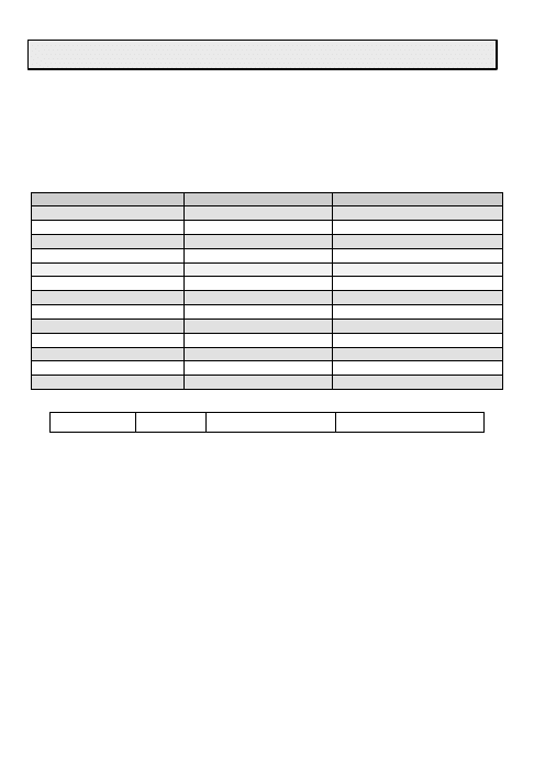
60
Perform the following procedure to send an Over The Air Re-key (OTAR) in
ANVDT mode using non-DAMA SATCOM.
Equipment Required: KYX-15 Fill Cable, KY-99 OTAR Adapter and UDC Cable
1. Fill KEK and the new TEK into any unused KYX-15/15A fill position. The
TEK must be stored in a lower position than the KEK.
2. Setup AN/PSC-5 as follows:
PARAMETER
SENDING STATION
RECEIVING STATION(S)
MODE SWITCH
PT
CT
MENU
CURRENT
CURRENT
MODE
SATCOM
SATCOM
P# or M#
TEK #
MODULATION
PSK
PSK
COMSEC MODE
ANDVT
VOICE/DATA
D2400
V2400
OP MODE
NORMAL
NORMAL
Tpwr
43 dBm
43dBm
CHAN # (Rx/Tx Freq)
AS RQD
AS RQD
INTERFACE
PSC-5
PSC-5
NONDIFF/DIFF
AS RQD
AS RQD
3. Setup KY-99 as follows:
POWER: ON
MODE: C
FILL Switch: As Req
FUNC Switch: OFF LINE
4. On KY-99 menu Scroll to INFC and then set the FUNCTION switch to CT.
5. Contact receiving station using current TEK. Notify receiving station to stand
by for AK operation.
6. On KYX-15/15A, set ADDRESS SELECT toggle switch for address
containing the new TEK to ON. Set all other ADDRESS SELECT toggle
switches to OFF.
7. Set ADDRESS SELECT switch for address containing the KEK to ON.
8. On KYX-15/15A, set Mode switch to AK.
9. On KYX-15/15A, press and release the INITIATE button. The KY-99 display
shows TX AK and the PARITY INDICATOR on the KYX-15/15A will flash. Wait
30 seconds.
10. Perform secure communications check with the receiving station. If
unsuccessful, repeat steps 1 through 9.
11. Upon successful re-key, the receiving radio’s KEK will be updated
automatically. The transmitting radio must manually fill KEK from KY-99 in
order for the keys to match.
SEND OTAR IN ANDVT MODE

61
Perform the following procedure to receive an OTAR. OTARs may be sent in a
VINSON mode using LOS or SATCOM or in ANDVT mode using SATCOM.
1. Ensure the terminal has the current TEK and KEK installed.
2. Set up AN/PSC-5 for LOS or SATCOM communications.
3. Wait for sending terminal to establish communications.
4. OTAR is received when “VINSON (or ANDVT) OTAR DETECTED” is
displayed.
NOTE: The terminal’s KEK is automatically updated upon receipt of a new
TEK.
5. Verify re-key by establishing communication with sending terminal.
RECEIVE OTAR
CLONING AND ERASING PARAMETERS
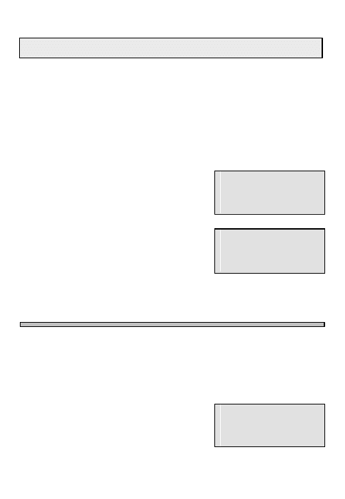
62
Perform the following procedure to clone terminal parameters from one
AN/PSC-5 to another. The radio will clone everything in the terminal except
the DAMA address and COMSEC keys.
1. Ensure radio sets are set to PT in LOS mode.
2. Connect cloning cable W7 to the AUX connector of each radio set.
3. On each radio set, press ESC until the main menu is displayed.
4. On each radio set, press 2. (Database Options)
5. On each radio set, press 8. (Clone Mode)
6. On the source radio set, ENTER the five-digit
DAMA address of the destination radio set.
7. On the source radio set, press ENT on SEND.
CLONE MODE
DAMA Address #####
{SEND}
8. Observe each radio set. The source radio will
display “Sending” and the destination radio will
display “Receiving." When complete, each will
display “Successful."
CLONE MODE
Sending - LOS
DAMA Address #####
9. If “Link Failure” is displayed on the source radio set, the transfer failed.
Repeat steps 1 thru 8. If the Cloning transfer continues to fail, check the
cloning cable.
Perform the following procedure to reset all parameters to factory default
parameters (excluding COMSEC keys).
1. Press ESC until the main menu is displayed.
2. Press 5. (Maintenance)
3. Press 5. (Erase Parameters)
4. Press ENT on ERASE.
5. Press ESC twice when done to return to the
main menu.
ERASE PARAMETERS
{ERASE}
CLONING AND ERASING PARAMETERS

63
The following footnotes are referenced throughout this manual (1).
1. Applies to message service only. Select manual to queue messages in
terminal, auto to release upon receipt. Defaults to manual whenever voice is
selected.
2. Terminal Time is required only for passive ranging. Time is also used in
Status Messages. Time is always reset to 00:00Z after radio is turned off.
3. Set Transmit Power as low as possible.
4. Orderwire is always encrypted.
5. Select Active or Passive. Not required in EMCON mode.
6. Satellite ID and Ephemeris data is used only when passive ranging.
7. Not Used.
8. Each terminal must have a unique Terminal Address.
9. Always include the network (Net Guard) address in the Guard List. Until
officially notified, DO NOT put terminal addresses in the guard list.
10. For Pre-assigned Login, demarcation point and call precedence are
required.
11. Maximum Call Precedence assigned to the terminal is in the SAR,
designated by unit frequency manager. In 25-kHz DAMA the terminal will not
indicate the maximum precedence.
12. Destination Addresses can be terminal or network address. Need network
address and all terminal addresses in net for making calls.
13. A checkmark indicates the Message has already been viewed.
14. Indefinite should always be used for network address.
15. Up and down arrows are displayed when orderwires are transmitted and
received.
16. M is displayed when orderwires are not received and decrypted. Check
antenna and power to remove M– if still there, refill the Orderwire key.
17. The acknowledgement message confirms the message was sent. It is not
from the receiving terminal.
18. Currently, no Codes are assigned; use the default value 00001.
19. To change preset parameters, move cursor to desired data field and
update then press ENT to confirm. The P (Preset) changes to M (Modified).
APPENDIX A FOOTNOTES
LIST OF ACRONYMS

64
AC
Automatic Control
ac
Alternating Current
AK
Automatic Keying
BER
Bit Error Rate
BIT
Built-In Test
bps
Bits per second
BPSK
Binary Phase Shift Keying
CC
Channel Controller
CCOW
Channel Control Orderwire
D
Data
DAMA
Demand Assigned Multiple Access
DASA
Demand Assigned Single Access
dBm
Decibels relative to 1 milliwatt
DC
Distributed Control
DIFF
Differential
EA
Emergency Action
EMCON Emergency Control
F
Flash
FO
Flash Override
FOW
Forward Orderwire
FSK
Frequency Shift Keying
KEK
Key Encryption Key
LIO
Limited Input/Output
LQ
Link Quality
MHOP
Multiple Satellite Hops
NDIFF
Non-Differential
NVM
Nonvolatile Memory
OTAR
Over-The-Air-Rekey
OW
Orderwire
P
Priority
PCC
Primary Channel Controller
PSK
Phase Shift Keying
R
Routine
RCCOW Return Channel Control Orderwire
ROW
Return Orderwire
RTS
Request to Send
SAA
Satellite Access Authorization
TDMA
Time Division Multiple Access
TSN
Time Slot Number
UPD
Update
LIST OF ACRONYMS
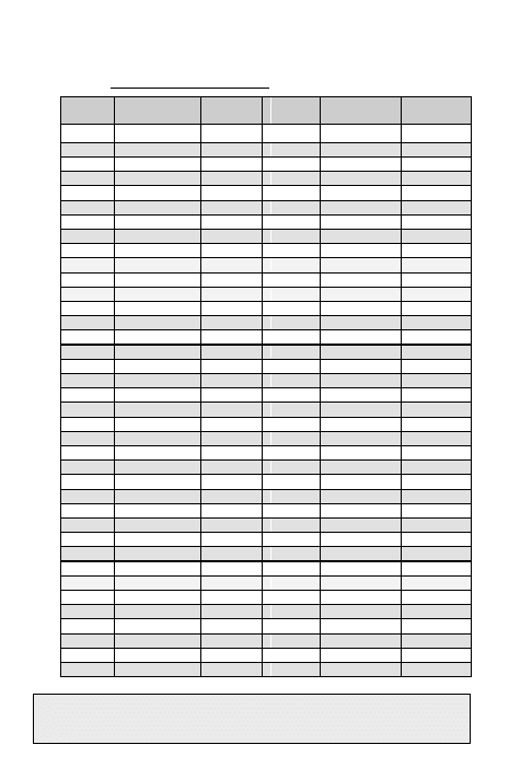
65
The following table lists satellite channels authorized for use with the radio set.
Table 19 25-kHz Satellite Channels (1-8 are not applicable)
CHAN
#
DOWNLINK
UPLINK
CHAN
#
DOWNLINK
UPLINK
1
250.350
SHF
39
268.350
309.350
2
250.400
SHF 40
268.450
309.450
3
250.450
SHF 41
269.650
310.650
4
250.500
SHF 42
269.750
310.750
5
250.550
SHF 43
269.850
310.850
6
250.600
SHF 44
269.950
310.950
7
250.650
SHF 45
260.350
293.950
8
250.700
SHF 46
260.375
293.975
9
251.850
292.850
47
260.400
294.000
10
251.950
292.950
48
260.425
294.025
11
252.050
293.050
49
260.450
294.050
12
252.150
293.150
50
260.475
294.075
13
253.550
294.550
51
260.500
294.100
14
253.650
294.650
52
260.525
294.125
15
253.750
294.750
53
260.550
294.150
16
253.850
294.850
54
260.575
294.175
17
255.250
296.250
55
260.600
294.200
18
255.350
296.350
56
260.625
294.225
19
255.450
296.450
57
260.650
294.250
20
255.550
296.550
58
260.675
294.275
21
256.850
297.850
59
260.700
294.300
22
256.950
297.950
60
260.725
294.325
23
257.050
298.050
61
260.750
294.350
24
257.150
298.150
62
260.775
294.375
25
258.350
299.350
63
260.800
294.400
26
258.450
299.450
64
260.825
294.425
27
258.550
299.550
65
260.850
294.450
28
258.650
299.650
66
261.450
295.050
29
265.250
306.250
67
261.475
295.075
30
265.350
306.350
68
261.500
295.100
31
265.450
306.450
69
261.525
295.125
32
265.550
306.550
70
261.550
295.150
33
266.750
307.750
71
261.575
295.175
34
266.850
307.850
72
261.600
295.200
35
266.950
307.950
73
261.625
295.225
36
267.050
308.050
74
261.650
295.250
37
268.150
309.150
75
261.675
295.275
38
268.250
309.250
76
261.700
295.300
25-kHz SATELLITE CHANNELS
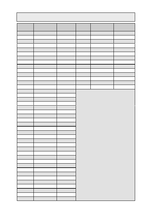
66
CHAN
#
DOWNLINK
UPLINK
CHAN
#
DOWNLINK
UPLINK
77
261.725
295.325
118
263.800 297.400
78
261.750
295.350
119
263.825 297.425
79
261.775
295.375
120
263.850 297.450
80
261.800
295.400
121
263.875 297.475
81
261.825
295.425
122
263.900 297.500
82
261.850
295.450
123
263.925 297.525
83
261.875
295.475
124
263.950 297.550
84
261.900
295.500
125
263.975 297.575
85
261.925
295.525
126
264.000 297.600
86
261.950
295.550
127
264.025 297.625
87
262.050
295.650
128
264.050 297.650
88
262.075
295.675
89
262.100
295.700
192
254.150 307.750
90
262.125
295.725
193
257.550 311.150
91
262.150
295.750
92
262.175
295.775
93
262.200
295.800
94
262.225
295.825
95
262.250
295.850
96
262.275
295.875
97
262.300
295.900
98
262.325
295.925
99
262.350
295.950
100
262.375
295.975
101
262.400 296.000
102
262.425 296.025
103
262.450 296.050
104
262.475 296.075
105
262.500 296.100
106
262.525 296.125
107
262.550 296.150
108
263.550 297.150
109
263.575 297.175
110
263.600 297.200
111
263.625 297.225
112
263.650 297.250
113
263.675 297.275
114
263.700 297.300
115
263.725 297.325
116
263.750 297.350
117
263.775 297.375
25-kHz SATELLITE CHANNELS

67
The following table lists satellite channels authorized for use with the radio
set.
Table 20 5-kHz Satellite Channels
CHAN
#
DOWNLINK
UPLINK
CHAN
#
DOWNLINK
UPLINK
129
248.845 302.445
166
249.150
302.750
130
248.850 302.450
167
249.155
302.755
131
248.855
302.455
168
249.165
302.765
132
248.865
302.465
169
249.175
302.775
133
248.875
302.475
170
249.185
302.785
134
248.885
302.485
171
249.195
302.795
135
248.895
302.495
172
249.200
302.800
136
248.900 302.500
173
249.205
302.805
137
248.905
302.505
174
249.215
302.815
138
248.915
302.515
175
249.225
302.825
139
248.925 302.525
176
249.235
302.835
140
248.935
302.535
177
249.245
302.845
141
248.945
302.545
178
249.250
302.850
142
248.950 302.550
179
249.255
302.855
143
248.955
302.555
180
249.265
302.865
144
248.965
302.565
181
249.275
302.875
145
248.975 302.575
182
249.285
302.885
146
248.985
302.585
183
249.295
302.895
147
248.995
302.595
184
249.300
302.900
148
249.000 302.600
185
249.305
302.905
149
249.005
302.605
186
249.315
302.915
150
249.015
302.615
187
249.325
302.925
151
249.025 302.625
188
249.335
302.935
152
249.035
302.635
189
249.345
302.945
153
249.045
302.645
190
249.350
302.950
154
249.050 302.650
191
249.355
302.955
155
249.055
302.655
156
249.065
302.665
157
249.075 302.675
194
243.855
316.955
158
249.085
302.685
195
243.860
316.960
159
249.095
302.695
196
243.875
316.975
160
249.100 302.700
197
243.900
317.000
161
249.105
302.705
198
243.910
317.010
162
249.115
302.715
199
243.915
317.015
163
249.125 302.725
200
243.925
317.025
164
249.135
302.735
201
243.935
317.035
165
249.145
302.745
202
243.945
317.045
5-kHz SATELLITE CHANNELS
68
CHAN
#
DOWNLINK
UPLINK
CHAN
#
DOWNLINK
UPLINK
203
243.955 317.055
223
244.105
317.205
204
243.965 317.065
224
244.110
317.210
205
243.975 317.075
225
244.115
317.215
206
243.985 317.085
226
244.125
317.225
207
243.990 317.090
227
244.135
317.235
208
243.995 317.095
228
244.145
317.245
209
244.000 317.100 229
244.155
317.255
210
244.005
317.105
230
244.165
317.265
211
244.010 317.110
231
244.175
317.275
212
244.015
317.115
232
244.185
317.285
213
244.025
317.125
233
244.190
317.290
214
244.035
317.135
234
244.195
317.295
215
244.045 317.145
235
244.200
317.300
216
244.055 317.155
236
244.205
317.305
217
244.065 317.165
237
244.210
317.310
218
244.075 317.175
238
244.215
317.315
219
244.085 317.185
239
244.225
317.325
220
244.090 317.190
221
244.095 317.195
222
244.100 317.200
5-kHz SATELLITE CHANNELS

By Order of the Secretary of the Army:
ERIC K. SHINSEKI
General, United States Army
Chief of Staff
Official:
Administrative Assistant to the
Secretary of the Army
xxxxxxxxxx
DISTRIBUTION:
To be distributed in accordance with the intial
Distribution number (IDN) 361032 requirements for TB
11-5820-1130-10-1.
By Order of the Secretary of the Air Force:
MICHAEL E. RYAN
General, United States Air Force
Chief of Staff
Official:
GEORGE T. BABBIT, JR.
General, United States Air Force
Commander, Air Force Material Command

PIN: 77443-000
Wyszukiwarka
Podobne podstrony:
Pocket Guide to Chemical Engineering
Pocket Guide to Chaos Magick
Electrician's Troubleshooting and Testing Pocket Guide
Templum Pocket Guide To Thelema
Pocket Guide to Kabbalah
Pocket Guide to Witchcraft
Templum Pocket Guide To Tarot
PMP Formula Pocket Guide
OReilly PHPUnit Pocket Guide (2006)
Pocket Linux Guide
User Guide Pocketbook IQ 701(RUS)
2002 Police Special Response Team SRT Guide 70p
The Official Guide to UFOs Compiled by the Editors of Science and Mechanics first published 1968 (
Answer Model Kartonowy Fana 2002 10 11 Spitfire Mk IX israel
więcej podobnych podstron