
Initial Print Date: 06/08
Table of Contents
Subject
Page
High Temperature in the ICOM A Working Environment . . . . . . . . . .8
Integrated Communication Optical Module
Revision Date:

2
ICOM
Integrated Communication Optical Module
(ICOM)
Model: All
Production: All
After completion of this module you will be able to:
• Identify the ICOM Modules.
• Explain and identify the purpose of the ICOM A, B, and C.
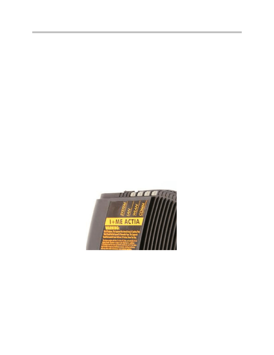
• Explain the purpose of the LEDs on the ICOM A.
3
ICOM
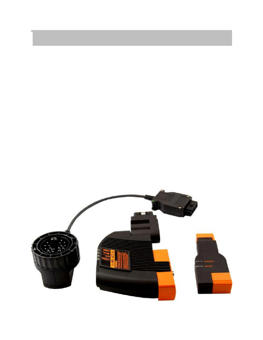
The Integrated Communication Optical Module (ICOM) is set of powerful vehicle inter-
faces to be used with the Integrated Service Information Display (ISID) device.
The ICOM consists of the following components:
• ICOM A is the basic component. Physically, it provides the interfaces for connec-
tion to the vehicle OBD II diagnostic interface on the one hand and the interfaces
for adaptive integration into the workshop network on the other. A powerful com-
puter core enables it to work as a protocol converter to assume the data inter-
change between the tester and the vehicle control units as well as the signal pro-
cessing for connection of the measurement system (IMIB). The power is supplied
by KL 30 across the vehicle interface.
• ICOM B is the external MOST (Media Oriented Systems Transport) interface for the
ICOM A. It is connected to the ICOM A using the supplied USB cable or a com-
mercially available USB cable of the type A-B. The power is supplied across the
ICOM A by way of a USB cable connection.
• ICOM C is an intelligent interface adapter that adapts the physical OBD II to the
BMW circular socket. As an extended supplementary module, it connects ICOM A
to vehicles without an OBD II female interface. The power supply is supplied at the
vehicle by way of KL 30 from the BMW 20 pin circular socket.
Introduction
ICOM A
4
ICOM
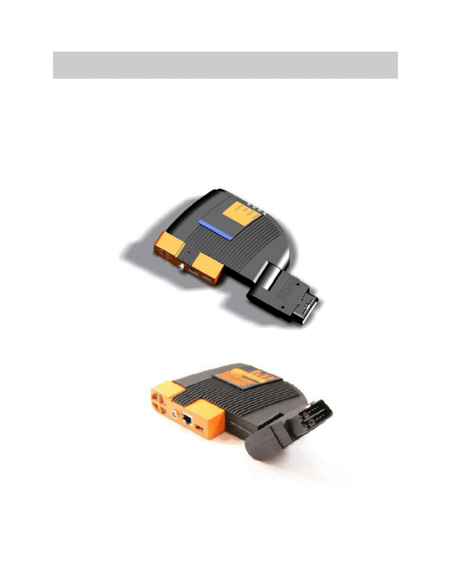
The ICOM A is the basic component. Physically, it provides the interfaces for connection
to the vehicle OBD II female diagnostic interface connector. A powerful computer core
enables it to work as a protocol converter to assume the data interchange between the
tester and the vehicle control units as well as the signal processing for connection of the
measurement system (IMIB). The power supply is supplied by way of KL 30 across the
vehicle interface. The ICOM A is specified rated in electrical operation for a minimum
voltage of 8 V. Stable operation is only ensured if the power supply is above the mini-
mum voltage limit.
5
ICOM
OBD II Pin
Interface Signal
1
Kl 15 (Ignition on)
2
SIA Reset signal
3
Ethernet Rx+
4
Ground (-)
5
Ground (-)
6
CAN High
7
K-Line 1
8
K-Line 2
9
TD Signal (RPM)
10
Not used
11
Ethernet Rx -
12
Ethernet Tx +
13
Ethernet Tx -
14
CAN Low
15
Not used
16
KL 30 (Battery Voltage)
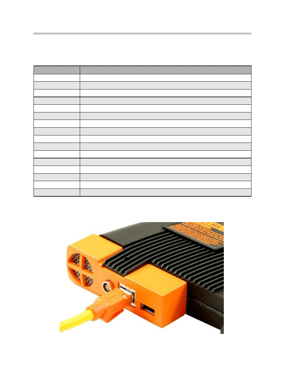
ICOM A can be connected to the workshop network by a Ethernet LAN cable
or wireless connection by WLAN. The maximum data rate is 100 Mbit/s.
ICOM A Vehicle Interfaces
ICOM A vehicle interfaces to the female 16 pin OBD II vehicle socket.
6
ICOM
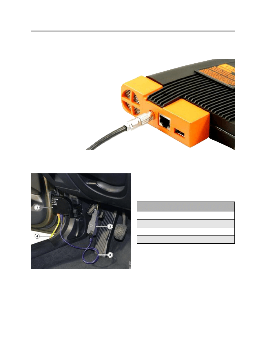
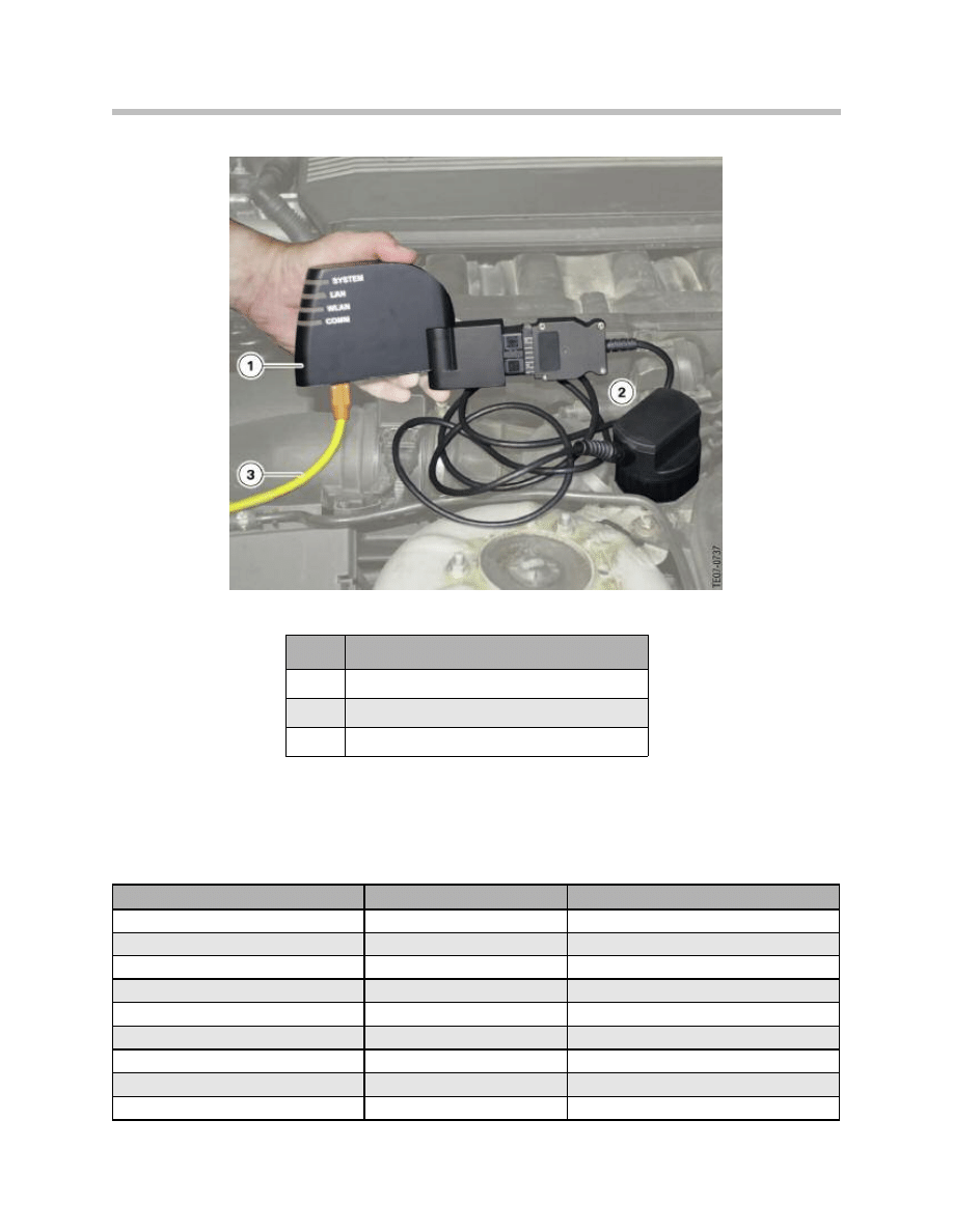
The IMIB can be connected by way of a LAN connector to the ICOM A.
The communication for the MOST Bus is supplied by ICOM B. For this purpose ICOM B
is to be connected with the ICOM A by way of a supplied USB cable.
The host communication is thru either a workshop network
LAN connection or WLAN.
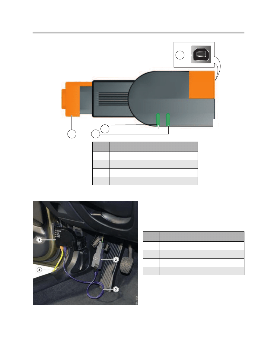
Index
Explanation
1
ICOM A
2
ICOM B
3
USB Cable (A B)
4
Ethernet Cable from Workshop Network
7
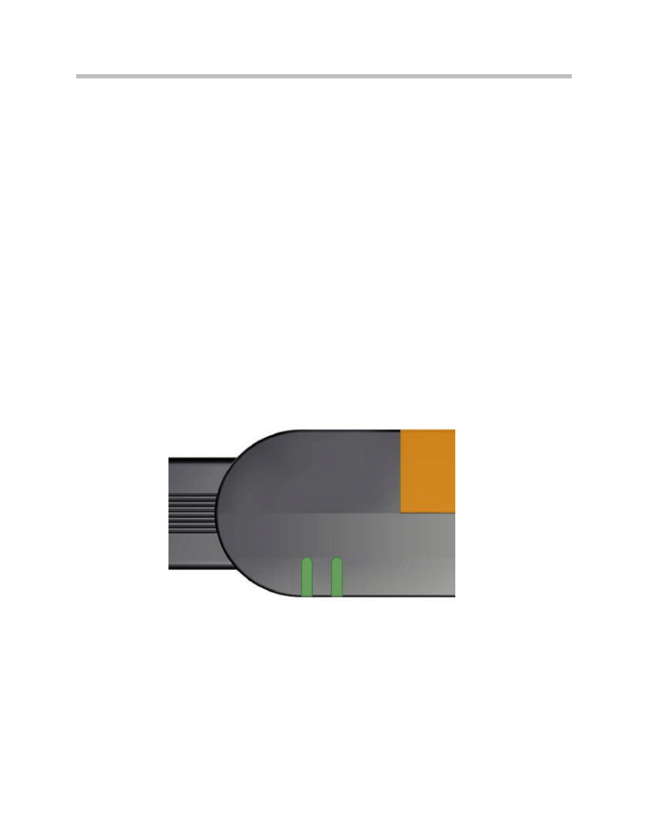
ICOM
The ICOM A includes a (4) four LED display. These LED’s displays the following informa-
tion and warnings:
• One 2-color LED label “SYSTEM” for the general status:
Green ------------------------------ system ready
Green flashing---------------------- system booting
Red --------------------------------- system fault
Off ---------------------------------- system off
• One 2-color LED label “LAN” for the status of ICOM A communication by Ethernet:
Green ------------------------------ Ethernet connection active (flashing if Traffic)
Off ---------------------------------- no LAN communication
• One 2-color LED label “WLAN” for the status of the ICOM A:
Green ------------------------------- Infrastructure (flashing if Traffic) Source: ISAP
Yellow ------------------------------- Ad-hoc (flashing if Traffic) ISAP offline
Off ----------------------------------- no WLAN communication
• One 2-color LED label “COMM” for the status of K-line, D_CAN or vehicle Ethernet
8
ICOM
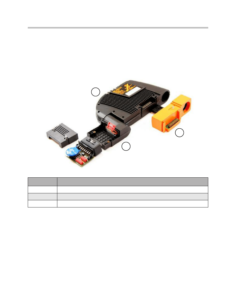
ICOM A Modular Structure
Due to a limited number of connect cycles, contact elements to connect assemblies are
subject to mechanical wear. The ICOM A concept enables replacement of wear parts, if
required, with minimum overhead in order to preserve full functions of the overall device
over a sustained period.
Wear parts are the OBD II module (2) and the fan / connector module (3).
High Temperature in the ICOM A Working Environment
High temperatures in the working environment of the ICOM A can have negative effects
on the hardware during regular operation. A separate fan is provided for the ICOM A tool
that is activated depending on the temperature increase inside the ICOM A. The fan
ensures that the air is circulated, thus protecting the ICOM A against heat damage.
The maximum permitted outside temperature is 45°C. If this limit value is exceed-
ed, an irreparable malfunction in the hardware can occur. (thermo shutdown takes place)
It must be ensured that the recirculation channel of the fan is not blocked by any objects
during regular operation. The fan is activated, when the temperature inside the ICOM A
exceeds a preset temperature value. The fan will remain on until the temperature drops
below a preset limit value.
Exploded view of individual parts
Index
Explanation
1
ICOM A Base Module
2
OBD II Module
3
Fan / Connector Module
1
3
2
ICOM B
9
ICOM
The ICOM B is the external MOST (Media Oriented Systems Transport) interface of the
ICOM A. It is connected to the ICOM A using the supplied USB cable or a commercially
available USB cable of the type A-B. The power is supplied across the ICOM A by way
of a USB cable connection.
During electrical operation, the ICOM B is only operational when the ICOM A is being
supplied with a minimum voltage of 8 V. If a cable other than that which is supplied is
used for the data connection for the ICOM A. The cable must complies with the USB
2.0 High Speed specification and is free of mechanical damage of any kind.
Note: Initially ICOM B will not be used for diagnostics. It is therefore,
not supported by Integrated Service Processes Application 2.x.
S
Y
S
T
E
M
M
O
S
T
10
ICOM
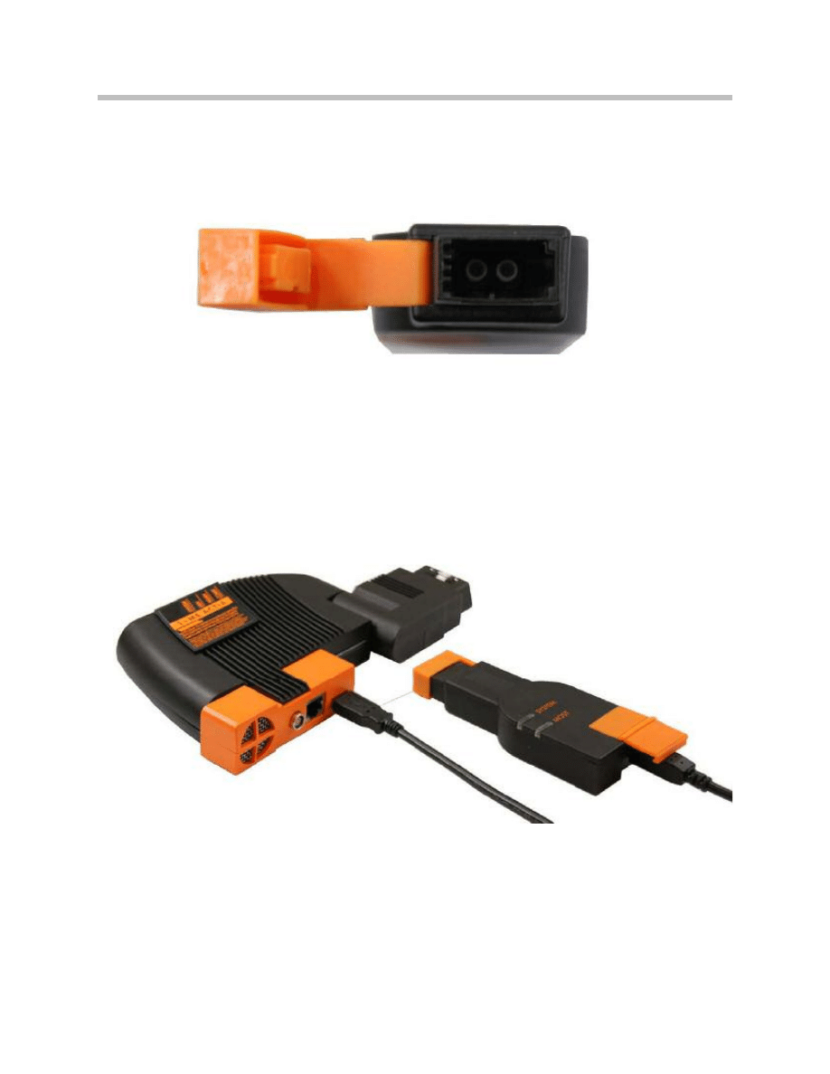
MOST interface ICOM B
Connection of ICOM A with ICOM B
11
ICOM
S
Y
S
T
E
M
M
O
S
T
1
3
2
4
Index
Explanation
1
USB Connection (Type B)
2
ICOM B “SYSTEM” status LED
3
“MOST” status LED
4
MOST interface connection
Index
Explanation
1
ICOM A
2
ICOM B
3
USB Cable (A B)
4
Ethernet Cable from Workshop Network
12
ICOM
The ICOM B includes a (2) two LED display. These LED’s displays the following informa-
tion and warnings:
• One 2-color LED label “SYSTEM” for the general status:
Off -------------------------------- no power or problems with power supply
Yellow ----------------------------- initializing ICOM B
Red flashing ---------------------- problems with booting/initializing
Green ----------------------------- ready
Green flashing -------------------- communication
• One 2-color LED label “MOST” for the status of MOST communication Ethernet:
Off --------------------------------- no light at MOST
Red -------------------------------- no lockable light
Green ------------------------------stable LOCK
Yellow *---------------------------- no stable LOCK
* Yellow = the relevant LED lights up simultaneously red and green.
S
Y
S
T
E
M
M
O
S
T
Light-emitting diodes on the ICOM B housing
ICOM C
13
ICOM
The ICOM C is an intelligent interface adapter that adapts the physical 16 pin female
OBD II socket to the BMW 20 pin circular socket. As an extended supplementary mod-
ule, it connects ICOM A to BMW vehicles which do not have a 16 pin OBD II female
interface. (older vehicles from the model E30 onwards). The power is supply from the
vehicle by way of KL 30 (+) of pin 14 of the BMW 20 pin circular socket.
The ICOM C is rated for electrical operation of a minimum voltage of 8 V. The voltage
at KL30 is routed inside the ICOM C to the OBD II. This is how power provided to the
ICOM A. Stable interaction of both devices (ICOM A & ICOM B) is only ensured when
the vehicle’s battery voltage is maintain above the 8 V minimum limit.
The BMW 20 pin round diagnostics connector contains a microprocessor that adapts
the read data from the vehicle to the data format of ICOM A. (a protocol convertor)
14
ICOM
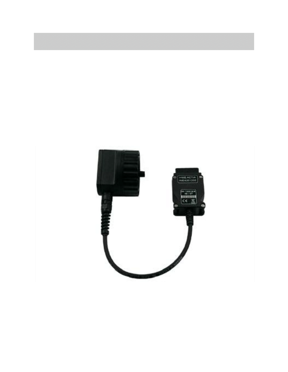
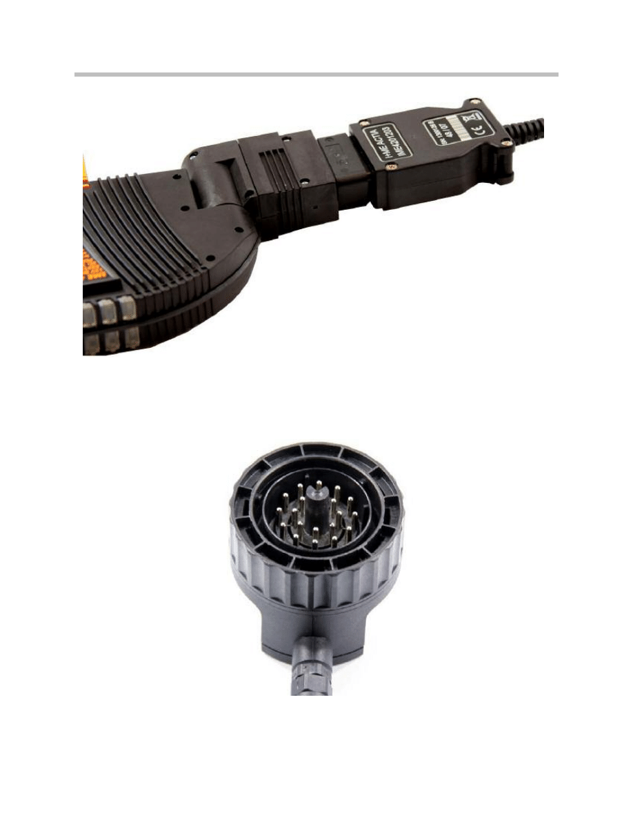
On the vehicle, the ICOM C is connected via the BMW 20 pin circular connector.
Connection of ICOM A with ICOM C
Circular connector of the ICOM C
15
ICOM
ICOM C Vehicle Interfaces
Following interfaces are supplied by ICOM C to ICOM A:
View of the ICOM A and ICOM C connected to a vehicle.
Index
Explanation
1
ICOM A
2
ICOM B
3
Workshop Network LAN Cable
Pin at 16 pin OBD II II Socket
Signal
Pin at 20 pin BMW round socket
1
KL 15 (Ignition on)
16
2
SIA Reset / Ethernet Activation
7
4
KL 31 (GND -)
19
5
KL 31 (GND -)
19
7
K-Line 1
17, 20
8
K-Line 2
18
9
KL 1 TD (RPM)
1
16
KL 30 (+)
14
-
Programming Voltage
18

16
ICOM
NOTES
PAGE
Document Outline
- Main Menu
- 01_Introduction to BMW
- 02_Features and Technology
- 03_Information Resources
- 04 Workshop Equipment
- 04a_ISIS.pdf
- 04b_ISID.pdf
- 04c_ICOM
- 04d_IMIB
- 04e_ISAP
- 05 Workshop Applications
- 05a_ISTA
- 05b_IMIB
- 05c_Understanding Diagnostics
- 05d_Coding and Programming
- 05e_ISTA-Programming
- 06_Service and Maintenance
- 07_PuMA
- 08_Basic Diagnostic Certification
Wyszukiwarka
Podobne podstrony:
BMW bluetooth Manual
BMW workshop manual install guide
BMW WORKSHOP MANUAL 2017 Installation Guide 5aea9a40e9cb5e491e77e344e521ede3
Bmw 01 94 Business Mid Radio Owners Manual
CARPROG BMW Key programmer manual
BMW M52TU engine training manual
BMW E38 E39 Wide Screen Monitor Service Manual
bmw canemu instalation manual
BMW CARSOFT 65 Manual id 90747 Nieznany (2)
ICOM instruction manual[1]
CARPROG BMW Airbag Reset manual
bmw e sys enet sf167 manual
Bmw 01 94 Business Mid Radio Owners Manual
CARPROG BMW Key programmer manual
bmw rheingold ista 3 icom
bmw ews immo emulator user manual EWS 2, 3 2 E34, E39, E36, E46, E38
więcej podobnych podstron