
"The repair methods given by the manufacturer in this document are based on the
technical specifications current when it was prepared.
The methods may be modified as a result of changes by the manufacturer in the
production of the various component units and accessories from which his vehicles
are constructed".
Supplement to manual F4P of JANUARY 1999
C
N.T. 3200A
CB0M
F4R
730
JA1B
F4R
740
F4R
741
X56P
F4R
780
JE0N
F4R
700
F4R
701
SPECIAL FEATURES
OF THE F4R ENGINE
Cancels and replaces Technical Note N
°
3238B of MAY 1999
For parts not dealt with in this Technical Note refer to Workshop Repair Manuals
MR 337-312-307-315
77 11 205 478
JUNE 1999
Edition Anglaise
All copyrights reserved by Renault.
Copying or translating, in part or in full, of this document or use of the service part
reference numbering system is forbidden without the prior written authority of
Renault.
RENAULT 1999

10-1
10-9
Specifications
Engine repair
Contents
Pages
ENGINE AND PERIPHERALS
ASSEMBLY
10
Timing belt
11-1
TOP AND FRONT OF ENGINE
11

This Technical Note deals with:
- the internal specifications of the F4R engine,
- replacement of the phase shifter solenoid valve seal,
- replacement of the timing belt and the camshaft seals.

ENGINE AND PERIPHERALS ASSEMBLY
Specifications
10
The specifications of the F4R engine are identical to those of the F4P engine with the exception of the follo-
wing specifications:
Engine
Index
Cubic capacity
(cm
3
)
Bore
(mm)
Stroke
(mm)
Compression
ratio
F4R
730
1998
82.7
93
11/1
F4R
700 - 701
740 - 741
780
1998
82.7
93
9.8/1
10-1

ENGINE AND PERIPHERALS ASSEMBLY
Specifications
10
CYLINDER HEAD
The bolts can be reused if the length under the head does not exceed 118.5 mm (otherwise change all the
bolts).
Cylinder head tightening procedure
REMINDER:
to achieve correct tightening of the bolts, remove any oil from the cylinder head securing holes
using a syringe.
Do not coat new bolts with oil. However, if the bolts are reused, it is essential to coat them with engine oil.
Tighten all the bolts to 2 daN.m in the order indicated below.
15153-1R
Check that all the bolts are correctly tightened to 2 daN.m, then carry out angular tightening (bolt by bolt) of
165
°
±
6
°
.
No retightening of the cylinder head bolts following application of this procedure.
10-2

ENGINE AND PERIPHERALS ASSEMBLY
Specifications
10
15156R
Details of mark (A) :
- mark (B) is only used by the supplier,
- mark (C) identifies the camshafts:
A
= Inlet
E
= Exhaust
- mark (D) indicates the engine type
F4R engine (except F4R 730)
F4RE668
104
14
22
B
C
D
VALVES
Valve lift (in mm)
F4R 730
F4R
(except
F4R 730)
Inlet
10.998
10.009
Exhaust
9.999
10.014
Valve spring (in mm)
F4R 730
F4R
(except
F4R 730)
Free length
43.57
41.30
Length under load:
- 27 daN
- 65 daN
- 19 daN
- 59 daN
34.50
23.50
-
-
-
-
34.50
24.50
Length with coils
touching max
22
23.20
Internal diameter
18.80
18.80
External diameter
27
27
F4R 730 engine
104
14
22 F4RE
B
C
D
Section of wire of the oval type.
CAMSHAFTS
The camshafts are identified:
- either by a mark (A),
10-3

ENGINE AND PERIPHERALS ASSEMBLY
Specifications
10
Timing diagram (cannot be checked)
F4R engine (except F4R 730)
Diagram with the intake not dephased
Inlet
camshaft
Cam 1
Cam 2
Exhaust
camshaft
Cam 1
Cam 2
Intake
opening
delay*
- 10
- 14
-
-
Intake
closing
delay
40
44
-
-
Exhaust
opening
advance
-
-
24
20
Exhaust
closing
advance**
-
-
- 4
0
Diagram with the intake dephased
Inlet
camshaft
Cam 1
Cam 2
Exhaust
camshaft
Cam 1
Cam 2
Intake
opening
delay*
6
2
-
-
Intake
closing
delay
24
28
-
-
Exhaust
opening
advance
-
-
24
20
Exhaust
closing
advance**
-
-
- 4
0
15152R
- F exhaust camshaft
- G inlet camshaft
- or by the ends of the camshafts.
F4R 730 engine
Diagram with the intake not dephased
Inlet
camshaft
Cam 1
Cam 2
Exhaust
camshaft
Cam 1
Cam 2
Intake
opening
delay*
- 7
- 11
-
-
Intake
closing
delay
61
65
-
-
Exhaust
opening
advance
-
-
41
37
Exhaust
closing
advance**
-
-
4
8
10-4

ENGINE AND PERIPHERALS ASSEMBLY
Specifications
10
Diagram with the intake dephased
Inlet
camshaft
Cam 1
Cam 2
Exhaust
camshaft
Cam 1
Cam 2
Intake
opening
delay*
9
5
-
-
Intake
closing
delay
45
49
-
-
Exhaust
opening
advance
-
-
41
37
Exhaust
closing
advance**
-
-
4
8
14515S
A 4 - 1 =
Intake of cylinder 4 and cam n
°
1.
E 4 - 1 =
Exhaust of cylinder 4 and cam n
°
1.
11953R
1
Cylinder block
TDC
fixed mark
2
Engine flywheel TDC movable mark
3
Engine flywheel
BDC
movable mark
4
Intake Opening Delay (IOD)
5
Exhaust Closing Advance (ECA)
6
Intake Closing Delay (ICD)
7
Exhaust Opening Advance (EOA)
*
As the Intake Opening Delay is negative, the
valves open after
TDC
.
**
As the Exhaust Closing Advance is negative,
the valves close before TDC.
10-5

ENGINE AND PERIPHERALS ASSEMBLY
Specifications
10
15521R
1
The direction of the piston
Λ
engine flywheel
side
2
The piston category (2-3 or A-B)
3
Only used by the supplier
4
Only used by the supplier
5
Piston line of symmetry
6
Piston pin hole line
7
Offset between the hole of line (6) and the
piston symmetry line (5) is 0.8 mm
8
Identification of the piston in relation to the
engine:
- 2
correspond
s to the
F4R
engine (except F4R
730)
,
- S corresponds to the F4R 730 engine
PISTONS
SMP piston
The pin is free in the connecting rod and in the
piston.
Piston marking
Marking of the diameter of the pistons in relation
to the diameter of the cylinder block
Piston
mark
Piston diameter (mm)
F4R
(except
F4R 730)
F4R 730
Cylinder
diameter
(mm)
2 or B
82.680
inclusive
to
82.690
exclusive
82.675
inclusive
to
82.685
exclusive
82.710
inclusive
to
82.720
exclusive
3 or C
82.690
inclusive
to
82.700
inclusive
82.685
inclusive
to
82.695
inclusive
82.720
inclusive
to
82.730
inclusive
10-6

ENGINE AND PERIPHERALS ASSEMBLY
Specifications
10
Category of cylinder block bores
WARNING: it is essential to match the piston and cylinder block bore diameters correctly. To do this:
the position of the holes "T", in relation to the mating surface of the cylinder block, makes it possible to iden-
tify the original nominal dimension of the bore, and consequently, the diameter of the corresponding pis-
tons.
15189R
NOTE: some cylinders blocks do not have a matching hole. This indicates that they are fitted with pistons of
category B or 2.
Position of holes T
on the cylinder block
Category mark
on the piston
Diameter of the bore
(in mm)
Piston diameter
(in mm)
F4R
(except
F4R 730)
F4R 730
T = 13 mm
2 or B
82.710 inclusive
to
82.720 exclusive
82.680 inclusive
to
82.690 exclusive
82.675 inclusive
to
82.685 exclusive
T = 19 mm
3 or C
82.720 inclusive
to
82.730 inclusive
82.690 inclusive
to
82.700 inclusive
82.685 inclusive
to
82.695 inclusive
10-7

ENGINE AND PERIPHERALS ASSEMBLY
Specifications
10
CONNECTING RODS
Lateral clearance of the big end (in mm):
0.22
to 0.402
Diametral clearance of the big end (in mm):
0.02 to 0.071
Centreline distance between the big end and the
little end (in mm):
144
±
0.035
Big end diameter (in mm):
51.587
Little end diameter (in mm):
- without ring:
23
- with ring:
21
CRANKSHAFT
Number of bearings:
5
Burnished journals:
- nominal diameter
(in
mm)
:
54.795
±
0.01
Burnished crank pins:
- nominal diameter (in mm)
48
Crankshaft lateral clearance (in mm):0.07 to 0.23
Crankshaft diametral clearance (in mm):
0.04 to 0.075
The side shims are on bearing n
°
2
.
- 0.02
0
+ 0.02
+ 0.01
+ 0.02
0
0
- 0.019
10-8

ENGINE AND PERIPHERALS ASSEMBLY
Engine repair
10
Replacement of the control solenoid valve seal
Remove:
- the coil,
- the solenoid valve,
15200S
- the seal.
The seal is refitted using tool Mot. 1513.
Refit in the reverse order to removal.
16016R
10-9

Angular tightening wrench
14 mm hexagonal wrench
TOP AND FRONT OF ENGINE
Timing belt
11
ESSENTIAL SPECIAL TOOLS
Mot. 799-01
Tool for immobilising pinions for
toothed timing belt
Mot. 1054
Top dead centre pin
Mot. 1487
Tool for refitting the inlet
camshaft plug
Mot. 1488
Tool for refitting the exhaust
camshaft plug
Mot. 1496
Tool for setting camshafts
Mot. 1509
Tool for immobilising camshaft
pulleys
Mot. 1509-01
Accessory for Mot. 1509
Mot. 1512
Tool for fitting the exhaust
camshaft seal
Mot. 1517
Tool for fitting the inlet camshaft
seal
ESSENTIAL EQUIPMENT
There are two very distinct procedures for setting
the timing.
1
st
PROCEDURE
The first procedure is applied in the event of re-
placement of any components which require
slackening of the exhaust camshaft pulley and of
the inlet camshaft phase shifter.
During this operation, it is essential to change:
- the exhaust camshaft pulley nut,
- the inlet camshaft phase shifter bolt,
- the phase shifter camshaft seal,
- the phase shifter blanking piece seal.
11-1

TOP AND FRONT OF ENGINE
Timing belt
11
15111R
- the inserts at the end of the camshafts,
15105S
- the Top Dead Centre pin plug.
15102-1S
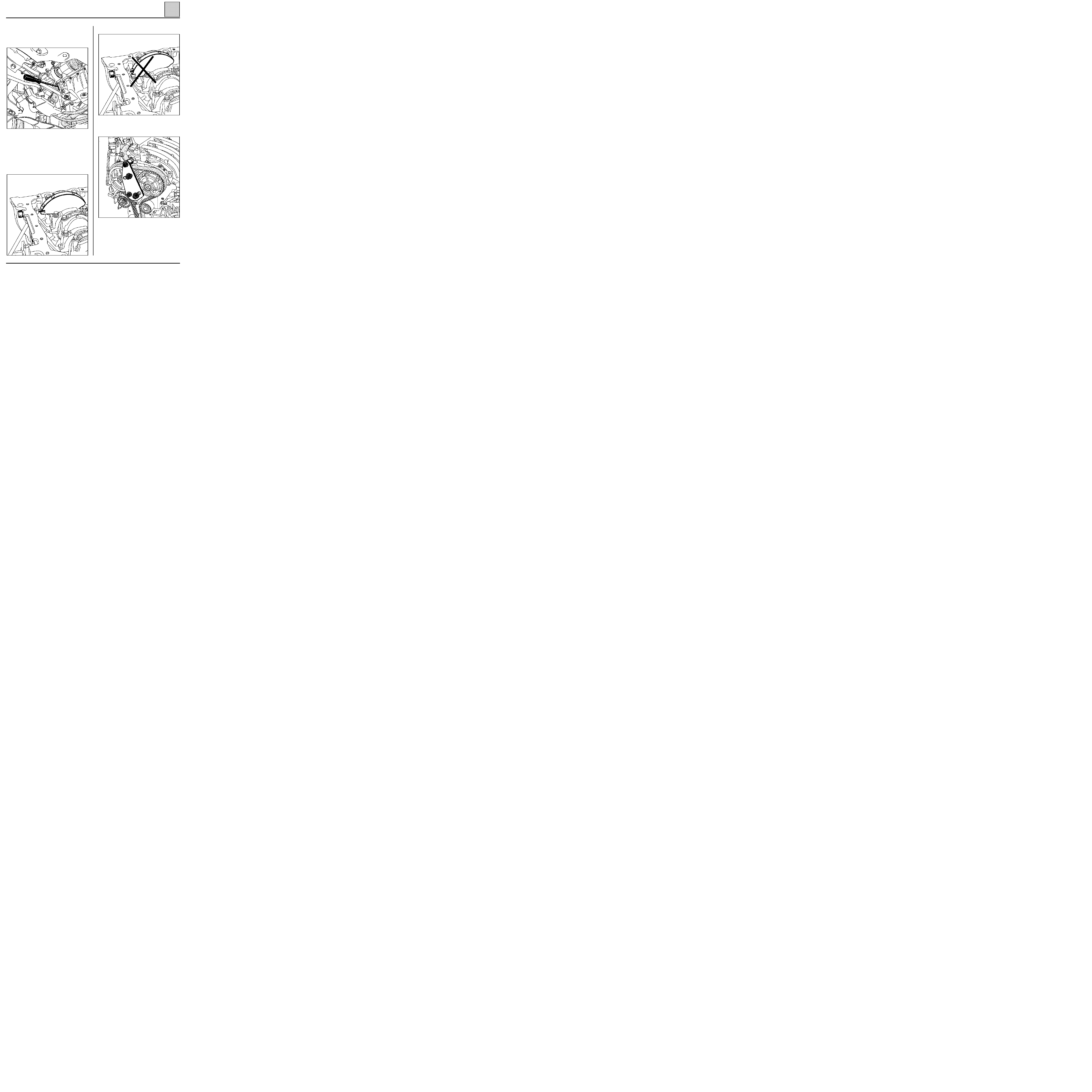
REMOVAL
Remove:
- the accessories belt; tilt the belt’s automatic
tensioner in the direction indicated below
using a 13 mm offset ring ended spanner.
Clamp the tensioner using a 6 mm hexagonal
wrench (1)
.
11-2

TOP AND FRONT OF ENGINE
Timing belt
11
15106S
15163-2S
NOTE: this is to avoid setting the crankshaft in a
balancing hole.
Incorrect position
15163S
Positioning the timing at the
setting point
Procedure
Position the camshaft grooves
downwards and almost hori-
zontal as indicated below,
then insert the Top Dead
Centre pin Mot. 1054 to be
between the balancing hole
and the crankshaft setting
groove.
11-3

TOP AND FRONT OF ENGINE
Timing belt
11
15106-1S
15163-1S
Turn the engine clockwise
(timing side), to the timing
setting point.
The camshaft grooves should
be horizontal and offset
downwards as indicated on the
diagram below.
11-4

TOP AND FRONT OF ENGINE
Timing belt
11
Immobilise the engine
flywheel using tool Mot. 582-
01 or a large screwdriver.
15815-1R
15303S
Remove:
- the crankshaft pulley,
- the intermediate timing
cover (1),
- the upper timing cover (2).
11-5

TOP AND FRONT OF ENGINE
Timing belt
11
15815-5R
Slacken the tensioner nut (1).
Remove:
- the pulley (2),
- the timing belt taking care
not to let the crankshaft ti-
ming pinion fall.
- the crankshaft timing pi-
nion.
11-6

TOP AND FRONT OF ENGINE
Timing belt
11
15865R
16014R
16017S
In its place fit the toothed pinion of tool
Mot. 1509-01
(reusing the two washers and the
nut of Mot. 1509).
16018S
Procedure for slackening the exhaust camshaft
pulley and the inlet camshaft phase shifter.
The operation is carried out using tools Mot. 1509
and Mot. 1509-01.
Preparation of tool Mot. 1509
Remove the upper toothed pinion from the
bracket.
11-7

TOP AND FRONT OF ENGINE
Timing belt
11
- the upper bolt (3) while positioning the spacer
(4) of tool Mot. 1509-01 between the tool and
the camshaft bearing cap housing (do not tigh-
ten the bolt)
.
- the flanged nut (5) of tool Mot. 1509-01.
- tool Mot. 1509 as indicated on the diagram be-
low,
16019R
16019-1S
16019-2R
16019-3R
Fit:
- the spacer (1) of tool Mot. 1509-09 on the stud
(2),
11-8

TOP AND FRONT OF ENGINE
Timing belt
11
16015R
16019-4R
16019-5S
16015-1R
Tighten the flanged nut (6) and the bolt (7), then
immobilise the pulleys using the toothed pinions
of tool Mot. 1509.
Remove:
- the inlet camshaft phase shifter blanking piece
using a 14 mm hexagonal wrench,
- the exhaust camshaft pulley nut,
- the inlet camshaft phase shifter bolt.
Fitting of the inlet camshaft phase shifter seal
using tool Mot. 1517 using the old bolt (2).
Replacement of the camshaft seals
Fitting of the exhaust camshaft seal using tool
Mot. 1512
using the old nut (1).
11-9

TOP AND FRONT OF ENGINE
Timing belt
11
Setting the timing
WARNING:
it is essential to degrease the end of the crankshaft (timing end), the
bore and the contact surfaces of the timing pinion, the contact surfaces
of the accessories pulley and the ends of the camshafts (timing end), the
bores and contact surfaces of the exhaust camshaft pulley and the inlet
camshaft phase shifter. This is to prevent sliding between the timing,
the crankshaft and the exhaust camshaft pulleys and the inlet phase
shifter which could destroy the engine.
NOTE:
to make it easier to place the grooves in a horizontal position, position
the camshaft pulley and phase shifter, then screw in place the old pulley
nut and the old phase shifter bolt tightening them to 1.5 daN.m
MAXIMUM, and position the pistons at mid-travel (to prevent any
contact between the valves and the pistons).
Place the camshaft grooves in a horizontal position as indicated on the
diagram below (turning the camshafts using tool Mot. 799-01 if necessa-
ry)
.
15106-1S
11-10

TOP AND FRONT OF ENGINE
Timing belt
11
Check that the inlet camshaft phase shifter crown wheel is immobilised
correctly (no rotation of the crown wheel to the left or the right).
15815-6S
11-11

TOP AND FRONT OF ENGINE
Timing belt
11
Fit tool Mot. 1496 which is secured to the end of
the camshafts.
15163S
Remove the old pulley nut and the old phase shif-
ter bolt and replace them with a new nut and bolt
(without tightening the nut and the bolt, clea-
rance of 0.5 to 1 mm between the nut or the bolt
and the pulley).
Check that the crankshaft is correctly pinned at
Top Dead Centre and not in the balancing hole
(the crankshaft groove (5) should be in the verti-
cal centreline of the engine).
15104R
Pinned crankshaft
15163-1S
15114-1R
Incorrect position
11-12

TOP AND FRONT OF ENGINE
Timing belt
11
When a timing belt is changed, it is essential to
change the timing tensioners and pulleys.
Check that the tensioner lug (1) is correctly posi-
tioned in the groove (2).
15201R
15815-7S
Refit:
- the timing belt,
- the crankshaft accessories pulley, pretightening the bolt (without fully tightening the bolt, clearance of 2
to 3 mm between bolt/pulley)
.
NOTE:
- the accessories crankshaft pulley bolt can be reused if the length under the head does does exceed 49.1
mm
(otherwise change it),
- do not oil a new bolt. However, if the old bolt is reused, it is essential to oil the threads and under the
head.
11-13

TOP AND FRONT OF ENGINE
Timing belt
11
15256R
Pretighten the tensioner nut to a torque of 0.7
daN.m.
NOTE:
check carefully that the nut and the bolt of
the camshaft pulleys do not come into contact
with their respective pulleys. Also, place the cams-
haft pulleys flush against the camshaft from time
to time.
Turn the timing six revolutions clockwise (timing
end) via the
exhaust pulley
using tool Mot. 799-
01
.
Align marks (6) and (7) if necessary, slackening the
tensioner nut by one revolution maximum while
retaining it using a 6 mm hexagonal wrench. Then
fully tighten the nut to a torque of 2.8 daN.m.
Tighten the accessories crankshaft pulley bolt to a
torque of 2 daN.m (Top Dead Centre pin still in
place in the crankshaft).
Belt tension
Check that there is still a clearance of 0.5 to 1 mm
between the nuts and the camshaft pulleys.
NOTE: do not turn the tensioner anti-clockwise.
Align tensioner marks (6) and (7) using a 6 mm
hexagonal wrench at (B).
11-14

TOP AND FRONT OF ENGINE
Timing belt
11
Using a pencil, make a mark (C) between the camshaft pulleys and the
camshaft bearing cap housing.
15815-8R
REMOVE THE TOP DEAD CENTRE PIN.
11-15
TOP AND FRONT OF ENGINE
Timing belt
11
Immobilise the engine flywheel using tool Mot.
582-01 or a large screwdriver
, then turn the acces-
sories crankshaft pulley bolt through an angle of
115
°
±
15
°
.
15303S
Pin the crankshaft using the marks made by the
operator between the camshaft pulleys and the
camshaft bearing cap housing. The marks must be
aligned as this ensures that the pin is in the pin
hole and not in the crankshaft balancing hole.
Correct position
15163-1S
Incorrect position
15163S
Fit the camshaft pulley immobilising tool Mot.
1509 fitted with the accessory Mot. 1509-01
.
16019-6S
11-16

TOP AND FRONT OF ENGINE
Timing belt
11
15163-2S
Pinned crankshaft
15163-1S
Tighten the new inlet camshaft phase shifter bolt
to a torque of 10 daN.m.
Tighten the exhaust camshaft pulley nut to a tor-
que of 3 daN.m, then turn through an angle of 86
°
±
6
°
.
Remove camshaft setting tool Mot. 1496, cams-
haft pulley immobilising tool Mot. 1509, and Top
Dead Centre pin Mot. 1054.
Checking the setting and tension
Checking the tension:
Turn the crankshaft two revolutions clockwise (ti-
ming end) and before the end of the two revolu-
tions (that is a half-tooth before alignment of the
marks made previously by the operator)
, insert
the crankshaft Top Dead Centre pin (to be bet-
ween the balancing hole and the pinning hole),
then move the timing to its setting point.
Before pinning
Remove the Top Dead Centre pin.
Check that the tensioner marks are correctly ali-
gned and repeat the tensioning procedure if they
are not. Slacken the tensioner nut by one revolu-
tion maximum while retaining it using a
6 mm
hexagonal wrench.
Align the tensioner marks and fully tighten the
nut to a torque of 2.8 daN.m.
11-17

TOP AND FRONT OF ENGINE
Timing belt
11
15106-1S
15104R
Refit the phase shifter blanking piece (1) (fitted
with its new seal) tightening it to a torque of 2.5
daN.m
.
16019-7R
Checking the setting
Ensure that the tensioner
marks are positioned correctly
before checking the timing set-
ting.
Fit the Top Dead Centre pin
(check that the marks made on
the camshaft pulleys by the
operator are aligned).
Fit (without using force) cams-
haft setting tool Mot. 1496
(the camshaft grooves should
be horizontal and offset down-
wards). If the tool does not en-
gage, the timing setting and
tensioning procedure must be
repeated.
11-18

TOP AND FRONT OF ENGINE
Timing belt
11
15110R
Fit the new sealing plugs:
- of the inlet camshaft (Mot. 1487),
- of the exhaust camshaft (Mot. 1488).
15103R
Refit in the reverse order to removal.
When refitting the accessories belt, it is essential
to check that the tooth "X" inside the pulleys (ti-
ming end) remains "free".
11-19

TOP AND FRONT OF ENGINE
Timing belt
11
2
nd
PROCEDURE
The second procedure is applied in the event of
replacement of any components on the timing
face which do not require slackening of the ex-
haust camshaft pulley and of the inlet camshaft
phase shifter.
For removal of the accessories belt and the timing
covers, refer to the beginning of the first proce-
dure.
11-20

TOP AND FRONT OF ENGINE
Timing belt
11
Setting the timing
WARNING: it is essential to de-
grease the end of the cranks-
haft, the bore and the contact
surfaces of the crankshaft pi-
nion and the contact surfaces
of the crankshaft pulley to pre-
vent sliding between the ti-
ming and the crankshaft which
could destroy the engine.
Position the camshaft grooves
downwards and almost hori-
zontal as indicated in the dia-
gram below, then insert the
Top Dead Centre pin Mot. 1054
to be between the balancing
hole and the crankshaft set-
ting groove.
15106S
15163-2S
NOTE: this is to avoid pinning the crankshaft in
the balancing hole.
Incorrect position
15163S
11-21

TOP AND FRONT OF ENGINE
Timing belt
11
Turn the engine clockwise (ti-
ming end), to the timing set-
ting point.
The camshaft grooves should
be horizontal and offset down-
wards as indicated on the dia-
gram opposite.
15106-1S
15163-1S
11-22

TOP AND FRONT OF ENGINE
Timing belt
11
Remove the Top Dead Centre pin.
Immobilise the engine flywheel using tool Mot.
582-01 or a large screwdriver.
15303S
15815-5R
Remove the accessories cranks-
haft pulley.
Slacken the timing tensioner
by unscrewing nut (1).
Remove the pulley (2).
11-23

TOP AND FRONT OF ENGINE
Timing belt
11
15163S
Remove the timing belt.
Fit tool Mot. 1496, which is secured at the end of
the camshafts.
Pinned crankshaft
15163-1S
15114-1R
15104R
Incorrect position
Check that the crankshaft is correctly pinned at
Top Dead Centre and not in the balancing hole (1)
(crankshaft groove (5) should be between the
two ribs (1) of the crankshaft closing cover).
11-24

TOP AND FRONT OF ENGINE
Timing belt
11
Also check that the inlet camshaft phase shifter crown wheel is immobi-
lised correctly (no rotation of the crown wheel to the left or to the
right).
15815-6S
11-25

TOP AND FRONT OF ENGINE
Timing belt
11
When a timing belt is changed, it is essential to
change the timing tensioners and pulleys.
Check that the tensioner lug (1) is correctly posi-
tioned in the groove (2).
WARNING: it is essential to degrease the end of
the crankshaft, the bore and the contact surfaces
of the crankshaft pinion, the contact surfaces of
the crankshaft pulley to prevent sliding between
the timing and the crankshaft which could des-
troy the engine.
15201R
- the crankshaft accessories pulley, pretightening the bolt (without fully tightening the bolt, clearance of 2
to 3 mm between bolt/pulley)
.
NOTE:
- the accessories crankshaft pulley bolt can be reused if the length under the head does does exceed 49.1
mm
(otherwise change it),
- do not oil a new bolt. However, if the old bolt is reused, it is essential to oil the threads and under the
head.
15815-7S
Refit:
- the timing belt,
11-26

TOP AND FRONT OF ENGINE
Timing belt
11
NOTE: do not turn the tensioner anti-clockwise.
Align tensioner marks (6) and (7) using a 6 mm
hexagonal wrench at (B).
15256R
Pretighten the tensioner nut to a torque of 0.7
daN.m.
Tighten the accessories crankshaft pulley bolt to a
torque of 2 daN.m (Top Dead Centre pin still in
place in the crankshaft).
11-27

TOP AND FRONT OF ENGINE
Timing belt
11
Make a mark (C) on the inlet
camshaft phase shifter crown
wheel and the exhaust pulley
in relation to the camshaft
bearing cap housing.
15815-8R
Remove camshaft setting tool Mot. 1496 and Top
Dead Centre pin Mot. 1054.
Carry out the angular tightening of the crankshaft
pulley bolt to 115
°
±
15
°
, while immobilising the
engine flywheel using a large screwdriver or tool
Mot. 582-01
.
15303S
11-28

TOP AND FRONT OF ENGINE
Timing belt
11
Turn the crankshaft two revolutions clockwise (ti-
ming end) and before the end of the two revolu-
tions (that is a half-tooth before alignment of the
marks made previously by the operator)
, insert
the crankshaft Top Dead Centre pin (to be bet-
ween the balancing hole and the pinning hole),
then move the timing to its setting point.
15163-2S
Correct position
15163-1S
Incorrect position
15163S
Remove Top Dead Centre pin Mot. 1054.
Check that the tensioner marks are correctly ali-
gned and repeat the tensioning procedure if they
are not. Slacken the tensioner nut by one revolu-
tion maximum while retaining it using a
6 mm
hexagonal wrench.
Align the tensioner marks and fully tighten the
nut to a torque of 2.8 daN.m.
Checking the setting and the tension
Checking the tension:
Turn the crankshaft two revolutions clockwise (ti-
ming end) and before the end of the two revolu-
tions (that is a half-tooth before alignment of the
marks made previously by the operator)
, insert
the crankshaft Top Dead Centre pin.
Remove Top Dead Centre pin Mot. 1054.
Check that the tensioner marks are correctly ali-
gned and repeat the tensioning procedure if they
are not. Slacken the tensioner nut by one revolu-
tion maximum while retaining it using a
6 mm
hexagonal wrench.
Align the tensioner marks and fully tighten the
nut to a torque of 2.8 daN.m.
11-29

TOP AND FRONT OF ENGINE
Timing belt
11
15106-1S
15104R
Checking the setting
Ensure that the tensioner
marks are positioned correctly
before checking the timing set-
ting.
Fit the Top Dead Centre pin
(check that the marks made on
the camshaft pulleys by the
operator are aligned).
Fit (without using force) cams-
haft setting tool Mot. 1496
(the camshaft grooves should
be horizontal and offset down-
wards). If the tool does not en-
gage, the timing setting and
tensioning procedure must be
repeated.
11-30
Document Outline
Wyszukiwarka
Podobne podstrony:
Top Sellable Personal Features of the Coaching Service
An experimental study on the development of a b type Stirling engine
MEPC 154(55) Designation of the Southern South African waters as a Special Area
From the design of a generic metamorphic engine to a black box classification of antivirus detection
British Patent 2,801 Improvements in Reciprocating Engines and Means for Regulating the Period of th
Honing the Tip of the Spear Developing an Operational Level Intelligence Preparation of the Battlefi
autismo prevalence of disorders of the autism spectrum in a population cohort of children in south t
Wiewiorowski Comes Hispaniarum Octavianus the special envoy of Constantine
Analysis And Reconstruction Of The 1974 Tornado Super Outbreak RMS Special Report
Scharnhorst Special Irreducible Matrix Repr of the Real CA C(3,1) (1998) [sharethefiles com]
After Allied Victory The Special Units Of Jews
The law of the European Union
A Behavioral Genetic Study of the Overlap Between Personality and Parenting
Pirates of the Spanish Main Smuggler's Song
Magiczne przygody kubusia puchatka 3 THE SILENTS OF THE LAMBS
An%20Analysis%20of%20the%20Data%20Obtained%20from%20Ventilat
więcej podobnych podstron