
Schneider Electric - Electrical installation guide 2008
A
© Schneider Electr
ic - all r
ights reser
ved
Chapter A
General rules of electrical
installation design
Contents
Methodology
A2
Rules and statutory regulations
A4
2.1 Definition of voltage ranges
A4
2.2 Regulations
A5
2.3 Standards
A5
2.4 Quality and safety of an electrical installation
A6
2.5 Initial testing of an installation
A6
2.6 Periodic check-testing of an installation
A7
2.7 Conformity (with standards and specifications) of equipment
used in the installation
A7
2.8 Environment
A8
Installed power loads - Characteristics
A0
3.1 Induction motors
A10
3.2 Resistive-type heating appliances and incandescent lamps
(conventional or halogen)
A12
Power loading of an installation
A5
4.1 Installed power (kW)
A15
4.2 Installed apparent power (kVA)
A15
4.3 Estimation of actual maximum kVA demand
A16
4.4 Example of application of factors ku and ks
A17
4.5 Diversity factor
A18
4.6 Choice of transformer rating
A19
4.7 Choice of power-supply sources
A20
2
3
4

Schneider Electric - Electrical installation guide 2008
A - General rules of electrical installation design
A2
© Schneider Electr
ic - all r
ights reser
ved
For the best results in electrical installation design it is recommended to read all the
chapters of this guide in the order in which they are presented.
Listing of power demands
The study of a proposed electrical installation requires an adequate understanding of
all governing rules and regulations.
The total power demand can be calculated from the data relative to the location and
power of each load, together with the knowledge of the operating modes (steady
state demand, starting conditions, non simultaneous operation, etc.)
From these data, the power required from the supply source and (where appropriate)
the number of sources necessary for an adequate supply to the installation are
readily obtained.
Local information regarding tariff structures is also required to allow the best choice
of connection arrangement to the power-supply network, e.g. at medium voltage or
low voltage level.
Service connection
This connection can be made at:
b
Medium Voltage level
A consumer-type substation will then have to be studied, built and equipped. This
substation may be an outdoor or indoor installation conforming to relevant standards
and regulations (the low-voltage section may be studied separately if necessary).
Metering at medium-voltage or low-voltage is possible in this case.
b
Low Voltage level
The installation will be connected to the local power network and will (necessarily) be
metered according to LV tariffs.
Electrical Distribution architecture
The whole installation distribution network is studied as a complete system.
A selection guide is proposed for determination of the most suitable architecture.
MV/LV main distribution and LV power distribution levels are covered.
Neutral earthing arrangements are chosen according to local regulations, constraints
related to the power-supply, and to the type of loads.
The distribution equipment (panelboards, switchgears, circuit connections, ...) are
determined from building plans and from the location and grouping of loads.
The type of premises and allocation can influence their immunity to external
disturbances.
Protection against electric shocks
The earthing system (TT, IT or TN) having been previously determined, then the
appropriate protective devices must be implemented in order to achieve protection
against hazards of direct or indirect contact.
Circuits and switchgear
Each circuit is then studied in detail. From the rated currents of the loads, the level
of short-circuit current, and the type of protective device, the cross-sectional area
of circuit conductors can be determined, taking into account the nature of the
cableways and their influence on the current rating of conductors.
Before adopting the conductor size indicated above, the following requirements must
be satisfied:
b
The voltage drop complies with the relevant standard
b
Motor starting is satisfactory
b
Protection against electric shock is assured
The short-circuit current
I
sc is then determined, and the thermal and electrodynamic
withstand capability of the circuit is checked.
These calculations may indicate that it is necessary to use a conductor size larger
than the size originally chosen.
The performance required by the switchgear will determine its type and
characteristics.
The use of cascading techniques and the discriminative operation of fuses and
tripping of circuit breakers are examined.
Methodology
A - General rules of electrical installation design
B – Connection to the MV utility distribution
network
C - Connection to the LV utility distribution
network
D - MV & LV architecture selection guide
F - Protection against electric shocks
G - Sizing and protection of conductors
H - LV switchgear: functions & selection
E - LV Distribution

Schneider Electric - Electrical installation guide 2008
A - General rules of electrical installation design
A3
© Schneider Electr
ic - all r
ights reser
ved
Protection against overvoltages
Direct or indirect lightning strokes can damage electrical equipment at a distance
of several kilometers. Operating voltage surges, transient and industrial frequency
over-voltage can also produce the same consequences.The effects are examined
and solutions are proposed.
Energy efficiency in electrial distribution
Implementation of measuring devices with an adequate communication system
within the electrical installation can produce high benefits for the user or owner:
reduced power consumption, reduced cost of energy, better use of electrical
equipment.
Reactive energy
The power factor correction within electrical installations is carried out locally,
globally or as a combination of both methods.
Harmonics
Harmonics in the network affect the quality of energy and are at the origin of many
disturbances as overloads, vibrations, ageing of equipment, trouble of sensitive
equipment, of local area networks, telephone networks. This chapter deals with the
origins and the effects of harmonics and explain how to measure them and present
the solutions.
Particular supply sources and loads
Particular items or equipment are studied:
b
Specific sources such as alternators or inverters
b
Specific loads with special characteristics, such as induction motors, lighting
circuits or LV/LV transformers
b
Specific systems, such as direct-current networks
Generic applications
Certain premises and locations are subject to particularly strict regulations: the most
common example being residential dwellings.
EMC Guidelines
Some basic rules must be followed in order to ensure Electromagnetic Compatibility.
Non observance of these rules may have serious consequences in the operation of
the electrical installation: disturbance of communication systems, nuisance tripping
of protection devices, and even destruction of sensitive devices.
Ecodial software
Ecodial software
(1)
provides a complete design package for LV installations, in
accordance with IEC standards and recommendations.
The following features are included:
b
Construction of one-line diagrams
b
Calculation of short-circuit currents
b
Calculation of voltage drops
b
Optimization of cable sizes
b
Required ratings of switchgear and fusegear
b
Discrimination of protective devices
b
Recommendations for cascading schemes
b
Verification of the protection of people
b
Comprehensive print-out of the foregoing calculated design data
J – Protection against voltage surges in LV
L - Power factor correction and harmonic filtering
N - Characteristics of particular sources and
loads
P - Residential and other special locations
M - Harmonic management
(1) Ecodial is a Merlin Gerin product and is available in French
and English versions.
Methodology
K – Energy efficiency in electrical distribution
Q - EMC guideline
Schneider Electric - Electrical installation guide 2008
A - General rules of electrical installation design
A4
© Schneider Electr
ic - all r
ights reser
ved
Low-voltage installations are governed by a number of regulatory and advisory texts,
which may be classified as follows:
b
Statutory regulations (decrees, factory acts,etc.)
b
Codes of practice, regulations issued by professional institutions, job specifications
b
National and international standards for installations
b
National and international standards for products
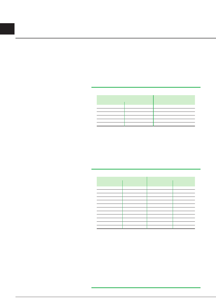
2. Definition of voltage ranges
IEC voltage standards and recommendations
2 Rules and statutory regulations
Three-phase four-wire or three-wire systems Single-phase three-wire systems
Nominal voltage (V)
Nominal voltage (V)
50 Hz
60 Hz
60 Hz
–
120/208
120/240
–
240
–
230/400
(1)
277/480
–
400/690
(1)
480
–
–
347/600
–
1000
600
–
(1) The nominal voltage of existing 220/380 V and 240/415 V systems shall evolve
toward the recommended value of 230/400 V. The transition period should be as short
as possible and should not exceed the year 2003. During this period, as a first step, the
electricity supply authorities of countries having 220/380 V systems should bring the
voltage within the range 230/400 V +6 %, -10 % and those of countries having
240/415 V systems should bring the voltage within the range 230/400 V +10 %,
-6 %. At the end of this transition period, the tolerance of 230/400 V ± 10 % should
have been achieved; after this the reduction of this range will be considered. All the
above considerations apply also to the present 380/660 V value with respect to the
recommended value 400/690 V.
Fig. A1
: Standard voltages between 100 V and 1000 V (IEC 60038 Edition 6.2 2002-07)
Series I
Series II
Highest voltage
Nominal system
Highest voltage
Nominal system
for equipment (kV)
voltage (kV)
for equipment (kV) voltage (kV)
3.6
(1)
3.3
(1)
3
(1)
4.40
(1)
4.16
(1)
7.2
(1)
6.6
(1)
6
(1)
–
–
12
11
10
–
–
–
–
–
13.2
(2)
12.47
(2)
–
–
–
13.97
(2)
13.2
(2)
–
–
–
14.52
(1)
13.8
(1)
(17.5)
–
(15)
–
–
24
22
20
–
–
–
–
–
26.4
(2)
24.94
(2)
36
(3)
33
(3)
–
–
–
–
–
–
36.5
34.5
40.5
(3)
–
35
(3)
–
–
These systems are generally three-wire systems unless otherwise indicated.
The values indicated are voltages between phases.
The values indicated in parentheses should be considered as non-preferred values. It is
recommended that these values should not be used for new systems to be constructed
in future.
Note : It is recommended that in any one country the ratio between two adjacent
nominal voltages should be not less than two.
Note 2: In a normal system of Series I, the highest voltage and the lowest voltage do
not differ by more than approximately ±10 % from the nominal voltage of the system.
In a normal system of Series II, the highest voltage does not differ by more then +5 %
and the lowest voltage by more than -10 % from the nominal voltage of the system.
(1) These values should not be used for public distribution systems.
(2) These systems are generally four-wire systems.
(3) The unification of these values is under consideration.
Fig. A2
: Standard voltages above 1 kV and not exceeding 35 kV
(IEC 60038 Edition 6.2 2002-07)

Schneider Electric - Electrical installation guide 2008
A - General rules of electrical installation design
A5
© Schneider Electr
ic - all r
ights reser
ved
2.2 Regulations
In most countries, electrical installations shall comply with more than one set of
regulations, issued by National Authorities or by recognized private bodies. It is
essential to take into account these local constraints before starting the design.
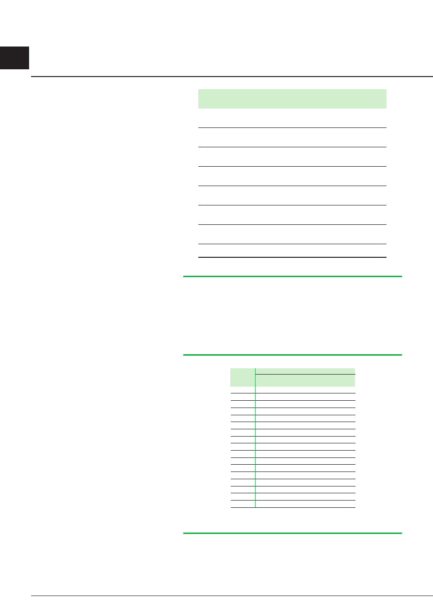
2.3 Standards
This Guide is based on relevant IEC standards, in particular IEC 60364. IEC 60364
has been established by medical and engineering experts of all countries in the
world comparing their experience at an international level. Currently, the safety
principles of IEC 60364 and 60479-1 are the fundamentals of most electrical
standards in the world (see table below and next page).
IEC 60038
Standard voltages
IEC 60076-2
Power transformers - Temperature rise
IEC 60076-3
Power transformers - Insulation levels, dielectric tests and external clearances in air
IEC 60076-5
Power transformers - Ability to withstand short-circuit
IEC 60076-0
Power transformers - Determination of sound levels
IEC 6046
Semiconductor convertors - General requirements and line commutated convertors
IEC 60255
Electrical relays
IEC 60265-
High-voltage switches - High-voltage switches for rated voltages above 1 kV and less than 52 kV
IEC 60269-
Low-voltage fuses - General requirements
IEC 60269-2
Low-voltage fuses - Supplementary requirements for fuses for use by unskilled persons (fuses mainly for household and similar applications)
IEC 60282-
High-voltage fuses - Current-limiting fuses
IEC 60287--
Electric cables - Calculation of the current rating - Current rating equations (100% load factor) and calculation of losses - General
IEC 60364
Electrical installations of buildings
IEC 60364-
Electrical installations of buildings - Fundamental principles
IEC 60364-4-4 Electrical installations of buildings - Protection for safety - Protection against electric shock
IEC 60364-4-42 Electrical installations of buildings - Protection for safety - Protection against thermal effects
IEC 60364-4-43 Electrical installations of buildings - Protection for safety - Protection against overcurrent
IEC 60364-4-44 Electrical installations of buildings - Protection for safety - Protection against electromagnetic and voltage disrurbance
IEC 60364-5-5 Electrical installations of buildings - Selection and erection of electrical equipment - Common rules
IEC 60364-5-52 Electrical installations of buildings - Selection and erection of electrical equipment - Wiring systems
IEC 60364-5-53 Electrical installations of buildings - Selection and erection of electrical equipment - Isolation, switching and control
IEC 60364-5-54 Electrical installations of buildings - Selection and erection of electrical equipment - Earthing arrangements
IEC 60364-5-55 Electrical installations of buildings - Selection and erection of electrical equipment - Other equipments
IEC 60364-6-6 Electrical installations of buildings - Verification and testing - Initial verification
IEC 60364-7-70 Electrical installations of buildings - Requirements for special installations or locations - Locations containing a bath tub or shower basin
IEC 60364-7-702 Electrical installations of buildings - Requirements for special installations or locations - Swimming pools and other basins
IEC 60364-7-703 Electrical installations of buildings - Requirements for special installations or locations - Locations containing sauna heaters
IEC 60364-7-704 Electrical installations of buildings - Requirements for special installations or locations - Construction and demolition site installations
IEC 60364-7-705 Electrical installations of buildings - Requirements for special installations or locations - Electrical installations of agricultural and horticultural
premises
IEC 60364-7-706 Electrical installations of buildings - Requirements for special installations or locations - Restrictive conducting locations
IEC 60364-7-707 Electrical installations of buildings - Requirements for special installations or locations - Earthing requirements for the installation of data
processing equipment
IEC 60364-7-708 Electrical installations of buildings - Requirements for special installations or locations - Electrical installations in caravan parks and caravans
IEC 60364-7-709 Electrical installations of buildings - Requirements for special installations or locations - Marinas and pleasure craft
IEC 60364-7-70 Electrical installations of buildings - Requirements for special installations or locations - Medical locations
IEC 60364-7-7 Electrical installations of buildings - Requirements for special installations or locations - Exhibitions, shows and stands
IEC 60364-7-72 Electrical installations of buildings - Requirements for special installations or locations - Solar photovoltaic (PV) power supply systems
IEC 60364-7-73 Electrical installations of buildings - Requirements for special installations or locations - Furniture
IEC 60364-7-74 Electrical installations of buildings - Requirements for special installations or locations - External lighting installations
IEC 60364-7-75 Electrical installations of buildings - Requirements for special installations or locations - Extra-low-voltage lighting installations
IEC 60364-7-77 Electrical installations of buildings - Requirements for special installations or locations - Mobile or transportable units
IEC 60364-7-740 Electrical installations of buildings - Requirements for special installations or locations - Temporary electrical installations for structures,
amusement devices and booths at fairgrounds, amusement parks and circuses
IEC 60427
High-voltage alternating current circuit-breakers
IEC 60439-
Low-voltage switchgear and controlgear assemblies - Type-tested and partially type-tested assemblies
IEC 60439-2
Low-voltage switchgear and controlgear assemblies - Particular requirements for busbar trunking systems (busways)
IEC 60439-3
Low-voltage switchgear and controlgear assemblies - Particular requirements for low-voltage switchgear and controlgear assemblies intended to
be installed in places where unskilled persons have access for their use - Distribution boards
IEC 60439-4
Low-voltage switchgear and controlgear assemblies - Particular requirements for assemblies for construction sites (ACS)
IEC 60446
Basic and safety principles for man-machine interface, marking and identification - Identification of conductors by colours or numerals
IEC 60439-5
Low-voltage switchgear and controlgear assemblies - Particular requirements for assemblies intended to be installed outdoors in public places
- Cable distribution cabinets (CDCs)
IEC 60479-
Effects of current on human beings and livestock - General aspects
IEC 60479-2
Effects of current on human beings and livestock - Special aspects
IEC 60479-3
Effects of current on human beings and livestock - Effects of currents passing through the body of livestock
(Continued on next page)
2 Rules and statutory regulations

Schneider Electric - Electrical installation guide 2008
A - General rules of electrical installation design
A6
© Schneider Electr
ic - all r
ights reser
ved
IEC 60529
Degrees of protection provided by enclosures (IP code)
IEC 60644
Spécification for high-voltage fuse-links for motor circuit applications
IEC 60664
Insulation coordination for equipment within low-voltage systems
IEC 6075
Dimensions of low-voltage switchgear and controlgear. Standardized mounting on rails for mechanical support of electrical devices in switchgear
and controlgear installations.
IEC 60724
Short-circuit temperature limits of electric cables with rated voltages of 1 kV (Um = 1.2 kV) and 3 kV (Um = 3.6 kV)
IEC 60755
General requirements for residual current operated protective devices
IEC 60787
Application guide for the selection of fuse-links of high-voltage fuses for transformer circuit application
IEC 6083
Shunt power capacitors of the self-healing type for AC systems having a rated voltage up to and including 1000 V - General - Performance, testing
and rating - Safety requirements - Guide for installation and operation
IEC 60947-
Low-voltage switchgear and controlgear - General rules
IEC 60947-2
Low-voltage switchgear and controlgear - Circuit-breakers
IEC 60947-3
Low-voltage switchgear and controlgear - Switches, disconnectors, switch-disconnectors and fuse-combination units
IEC 60947-4-
Low-voltage switchgear and controlgear - Contactors and motor-starters - Electromechanical contactors and motor-starters
IEC 60947-6-
Low-voltage switchgear and controlgear - Multiple function equipment - Automatic transfer switching equipment
IEC 6000
Electromagnetic compatibility (EMC)
IEC 640
Protection against electric shocks - common aspects for installation and equipment
IEC 6557-
Electrical safety in low-voltage distribution systems up to 1000 V AC and 1500 V DC - Equipment for testing, measuring or monitoring of protective
measures - General requirements
IEC 6557-8
Electrical safety in low-voltage distribution systems up to 1000 V AC and 1500 V DC - Equipment for testing, measuring or monitoring of protective
measures
IEC 6557-9
Electrical safety in low-voltage distribution systems up to 1000 V AC and 1500 V DC - Equipment for insulation fault location in IT systems
IEC 6557-2
Electrical safety in low-voltage distribution systems up to 1000 V AC and 1500 V DC - Equipment for testing, measuring or monitoring of protective
measures. Performance measuring and monitoring devices (PMD)
IEC 6558-2-6 Safety of power transformers, power supply units and similar - Particular requirements for safety isolating transformers for general use
IEC 6227-
Common specifications for high-voltage switchgear and controlgear standards
IEC 6227-00 High-voltage switchgear and controlgear - High-voltage alternating-current circuit-breakers
IEC 6227-02 High-voltage switchgear and controlgear - Alternating current disconnectors and earthing switches
IEC 6227-05 High-voltage switchgear and controlgear - Alternating current switch-fuse combinations
IEC 6227-200 High-voltage switchgear and controlgear - Alternating current metal-enclosed switchgear and controlgear for rated voltages above 1 kV and up to
and including 52 kV
IEC 6227-202 High-voltage/low voltage prefabricated substations
(Concluded)
2.4 Quality and safety of an electrical installation
In so far as control procedures are respected, quality and safety will be assured
only if:
b
The initial checking of conformity of the electrical installation with the standard and
regulation has been achieved
b
The electrical equipment comply with standards
b
The periodic checking of the installation recommended by the equipment
manufacturer is respected.
2.5 Initial testing of an installation
Before a utility will connect an installation to its supply network, strict pre-
commissioning electrical tests and visual inspections by the authority, or by its
appointed agent, must be satisfied.
These tests are made according to local (governmental and/or institutional)
regulations, which may differ slightly from one country to another. The principles of
all such regulations however, are common, and are based on the observance of
rigorous safety rules in the design and realization of the installation.
IEC 60364-6-61 and related standards included in this guide are based on an
international consensus for such tests, intended to cover all the safety measures and
approved installation practices normally required for residential, commercial and (the
majority of) industrial buildings. Many industries however have additional regulations
related to a particular product (petroleum, coal, natural gas, etc.). Such additional
requirements are beyond the scope of this guide.
The pre-commissioning electrical tests and visual-inspection checks for installations
in buildings include, typically, all of the following:
b
Insulation tests of all cable and wiring conductors of the fixed installation, between
phases and between phases and earth
b
Continuity and conductivity tests of protective, equipotential and earth-bonding
conductors
b
Resistance tests of earthing electrodes with respect to remote earth
b
Verification of the proper operation of the interlocks, if any
b
Check of allowable number of socket-outlets per circuit
2 Rules and statutory regulations

Schneider Electric - Electrical installation guide 2008
A - General rules of electrical installation design
A7
© Schneider Electr
ic - all r
ights reser
ved
2 Rules and statutory regulations
b
Cross-sectional-area check of all conductors for adequacy at the short-circuit
levels prevailing, taking account of the associated protective devices, materials and
installation conditions (in air, conduit, etc.)
b
Verification that all exposed- and extraneous metallic parts are properly earthed
(where appropriate)
b
Check of clearance distances in bathrooms, etc.
These tests and checks are basic (but not exhaustive) to the majority of installations,
while numerous other tests and rules are included in the regulations to cover
particular cases, for example: TN-, TT- or IT-earthed installations, installations based
on class 2 insulation, SELV circuits, and special locations, etc.
The aim of this guide is to draw attention to the particular features of different types
of installation, and to indicate the essential rules to be observed in order to achieve
a satisfactory level of quality, which will ensure safe and trouble-free performance.
The methods recommended in this guide, modified if necessary to comply with any
possible variation imposed by a utility, are intended to satisfy all precommissioning
test and inspection requirements.
2.6 Periodic check-testing of an installation
In many countries, all industrial and commercial-building installations, together with
installations in buildings used for public gatherings, must be re-tested periodically by
authorized agents.
Figure A3 shows the frequency of testing commonly prescribed according to the
kind of installation concerned.
Fig A3
: Frequency of check-tests commonly recommended for an electrical installation
2.7 Conformity (with standards and specifications)
of equipment used in the installation
Attestation of conformity
The conformity of equipment with the relevant standards can be attested:
b
By an official mark of conformity granted by the certification body concerned, or
b
By a certificate of conformity issued by a certification body, or
b
By a declaration of conformity from the manufacturer
The first two solutions are generally not available for high voltage equipment.
Declaration of conformity
Where the equipment is to be used by skilled or instructed persons, the
manufacturer’s declaration of conformity (included in the technical documentation),
is generally recognized as a valid attestation. Where the competence of the
manufacturer is in doubt, a certificate of conformity can reinforce the manufacturer’s
declaration.
Type of installation
Testing
frequency
Installations which
b
Locations at which a risk of degradation, Annually
require the protection
fire or explosion exists
of employees
b
Temporary installations at worksites
b
Locations at which MV installations exist
b
Restrictive conducting locations
where mobile equipment is used
Other cases
Every 3 years
Installations in buildings
According to the type of establishment
From one to
used for public gatherings, and its capacity for receiving the public
three years
where protection against
the risks of fire and panic
are required
Residential
According to local regulations
Conformity of equipment with the relevant
standards can be attested in several ways

Schneider Electric - Electrical installation guide 2008
A - General rules of electrical installation design
A8
© Schneider Electr
ic - all r
ights reser
ved
Note: CE marking
In Europe, the European directives require the manufacturer or his authorized
representative to affix the CE marking on his own responsibility. It means that:
b
The product meets the legal requirements
b
It is presumed to be marketable in Europe
The CE marking is neither a mark of origin nor a mark of conformity.
Mark of conformity
Marks of conformity are affixed on appliances and equipment generally used by
ordinary non instructed people (e.g in the field of domestic appliances). A mark of
conformity is delivered by certification body if the equipment meet the requirements
from an applicable standard and after verification of the manufacturer’s quality
management system.
Certification of Quality
The standards define several methods of quality assurance which correspond to
different situations rather than to different levels of quality.
Assurance
A laboratory for testing samples cannot certify the conformity of an entire production
run: these tests are called type tests. In some tests for conformity to standards,
the samples are destroyed (tests on fuses, for example).
Only the manufacturer can certify that the fabricated products have, in fact,
the characteristics stated.
Quality assurance certification is intended to complete the initial declaration or
certification of conformity.
As proof that all the necessary measures have been taken for assuring the quality of
production, the manufacturer obtains certification of the quality control system which
monitors the fabrication of the product concerned. These certificates are issued
by organizations specializing in quality control, and are based on the international
standard ISO 9001: 2000.
These standards define three model systems of quality assurance control
corresponding to different situations rather than to different levels of quality:
b
Model 3 defines assurance of quality by inspection and checking of final products.
b
Model 2 includes, in addition to checking of the final product, verification of the
manufacturing process. For example, this method is applied, to the manufacturer of
fuses where performance characteristics cannot be checked without destroying the
fuse.
b
Model 1 corresponds to model 2, but with the additional requirement that the
quality of the design process must be rigorously scrutinized; for example, where it is
not intended to fabricate and test a prototype (case of a custom-built product made to
specification).
2.8 Environment
Environmental management systems can be certified by an independent body if they
meet requirements given in ISO 14001. This type of certification mainly concerns
industrial settings but can also be granted to places where products are designed.
A product environmental design sometimes called “eco-design” is an approach of
sustainable development with the objective of designing products/services best
meeting the customers’ requirements while reducing their environmental impact
over their whole life cycle. The methodologies used for this purpose lead to choose
equipment’s architecture together with components and materials taking into account
the influence of a product on the environment along its life cycle (from extraction of
raw materials to scrap) i.e. production, transport, distribution, end of life etc.
In Europe two Directives have been published, they are called:
b
RoHS Directive (Restriction of Hazardous Substances) coming into force on
July 2006 (the coming into force was on February 13
th
, 2003, and the application
date is July 1
st
, 2006) aims to eliminate from products six hazardous substances:
lead, mercury, cadmium, hexavalent chromium, polybrominated biphenyls (PBB) or
polybrominated diphenyl ethers (PBDE).
2 Rules and statutory regulations

Schneider Electric - Electrical installation guide 2008
A - General rules of electrical installation design
A9
© Schneider Electr
ic - all r
ights reser
ved
2 Rules and statutory regulations
b
WEEE Directive (Waste of Electrical and Electronic Equipment) coming into
force in August 2005 (the coming into force was on February 13
th
, 2003, and
the application date is August 13
th
, 2005) in order to master the end of life and
treatments for household and non household equipment.
In other parts of the world some new legislation will follow the same objectives.
In addition to manufacturers action in favour of products eco-design, the contribution
of the whole electrical installation to sustainable development can be significantly
improved through the design of the installation. Actually, it has been shown that an
optimised design of the installation, taking into account operation conditions, MV/LV
substations location and distribution structure (switchboards, busways, cables),
can reduce substantially environmental impacts (raw material depletion, energy
depletion, end of life)
See chapter D about location of the substation and the main LV switchboard.

Schneider Electric - Electrical installation guide 2008
A - General rules of electrical installation design
A0
© Schneider Electr
ic - all r
ights reser
ved
3 Installed power loads -
Characteristics
The examination of actual values of apparent-power required by each load enables
the establishment of:
b
A declared power demand which determines the contract for the supply of energy
b
The rating of the MV/LV transformer, where applicable (allowing for expected
increased load)
b
Levels of load current at each distribution board
3. Induction motors
Current demand
The full-load current
I
a supplied to the motor is given by the following formulae:
b
3-phase motor:
I
a = Pn x 1,000 /
(√
3 x U x
η
x cos
ϕ)
b
1-phase motor:
I
a = Pn x 1,000 / (U x
η
x cos
ϕ)
where
I
a: current demand (in amps)
Pn: nominal power (in kW)
U: voltage between phases for 3-phase motors and voltage between the terminals
for single-phase motors (in volts). A single-phase motor may be connected phase-to-
neutral or phase-to-phase.
η
: per-unit efficiency, i.e. output kW / input kW
cos
ϕ
: power factor, i.e. kW input / kVA input
Subtransient current and protection setting
b
Subtransient current peak value can be very high ; typical value is about 12
to 15 times the rms rated value
I
nm. Sometimes this value can reach 25 times
I
nm.
b
Merlin Gerin circuit-breakers, Telemecanique contactors and thermal relays are
designed to withstand motor starts with very high subtransient current (subtransient
peak value can be up to 19 times the rms rated value
I
nm).
b
If unexpected tripping of the overcurrent protection occurs during starting, this
means the starting current exceeds the normal limits. As a result, some maximum
switchgear withstands can be reached, life time can be reduced and even some
devices can be destroyed. In order to avoid such a situation, oversizing of the
switchgear must be considered.
b
Merlin Gerin and Telemecanique switchgears are designed to ensure the
protection of motor starters against short-circuits. According to the risk, tables show
the combination of circuit-breaker, contactor and thermal relay to obtain type 1 or
type 2 coordination (see chapter N).
Motor starting current
Although high efficiency motors can be found on the market, in practice their starting
currents are roughly the same as some of standard motors.
The use of start-delta starter, static soft start unit or variable speed drive allows to
reduce the value of the starting current (Example : 4
I
a instead of 7.5
I
a).
Compensation of reactive-power (kvar) supplied to induction motors
It is generally advantageous for technical and financial reasons to reduce the current
supplied to induction motors. This can be achieved by using capacitors without
affecting the power output of the motors.
The application of this principle to the operation of induction motors is generally
referred to as “power-factor improvement” or “power-factor correction”.
As discussed in chapter L, the apparent power (kVA) supplied to an induction motor
can be significantly reduced by the use of shunt-connected capacitors. Reduction
of input kVA means a corresponding reduction of input current (since the voltage
remains constant).
Compensation of reactive-power is particularly advised for motors that operate for
long periods at reduced power.
As noted above
As noted above cos =
kW input
kVA input
so that a kVA input reduction in kVA input will
increase (i.e. improve) the value of cos
so that a kVA input reduction will increase
(i.e. improve) the value of cos
ϕ
.
An examination of the actual apparent-
power demands of different loads: a
necessary preliminary step in the design of a
LV installation
The nominal power in kW (Pn) of a motor
indicates its rated equivalent mechanical power
output.
The apparent power in kVA (Pa) supplied to
the motor is a function of the output, the motor
efficiency and the power factor.
Pa =
Pn
cos
η
ϕ

Schneider Electric - Electrical installation guide 2008
A - General rules of electrical installation design
A
© Schneider Electr
ic - all r
ights reser
ved
The current supplied to the motor, after power-factor correction, is given by:
I
cos
cos '
=
I
a
where cos
ϕ
is the power factor before compensation and cos
ϕ
’ is the power factor
after compensation,
I
a being the original current.
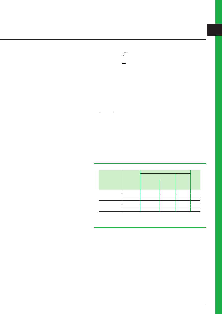
Figure A4 below shows, in function of motor rated power, standard motor current
values for several voltage supplies.
3 Installed power loads -
Characteristics
kW
hp
230 V
380 -
400 V
440 -
500 V
690 V
45 V
480 V
A
A
A
A
A
A
0.18
-
1.0
-
0.6
-
0.48
0.35
0.25
-
1.5
-
0.85
-
0.68
0.49
0.37
-
1.9
-
1.1
-
0.88
0.64
-
1/2
-
1.3
-
1.1
-
-
0.55
-
2.6
-
1.5
-
1.2
0.87
-
3/4
-
1.8
-
1.6
-
-
-
1
-
2.3
-
2.1
-
-
0.75
-
3.3
-
1.9
-
1.5
1.1
1.1
-
4.7
-
2.7
-
2.2
1.6
-
1-1/2
-
3.3
-
3.0
-
-
-
2
-
4.3
-
3.4
-
-
1.5
-
6.3
-
3.6
-
2.9
2.1
2.2
-
8.5
-
4.9
-
3.9
2.8
-
3
-
6.1
-
4.8
-
-
3.0
-
11.3
-
6.5
-
5.2
3.8
3.7
-
-
-
-
-
-
-
4
-
15
9.7
8.5
7.6
6.8
4.9
5.5
-
20
-
11.5
-
9.2
6.7
-
7-1/2
-
14.0
-
11.0
-
-
-
10
-
18.0
-
14.0
-
-
7.5
-
27
-
15.5
-
12.4
8.9
11
-
38.0
-
22.0
-
17.6
12.8
-
15
-
27.0
-
21.0
-
-
-
20
-
34.0
-
27.0
-
-
15
-
51
-
29
-
23
17
18.5
-
61
-
35
-
28
21
-
25
-
44
-
34
-
22
-
72
-
41
-
33
24
-
30
-
51
-
40
-
-
-
40
-
66
-
52
-
-
30
-
96
-
55
-
44
32
37
-
115
-
66
-
53
39
-
50
-
83
-
65
-
-
-
60
-
103
-
77
-
-
45
-
140
-
80
-
64
47
55
-
169
-
97
-
78
57
-
75
-
128
-
96
-
-
-
100
-
165
-
124
-
-
75
-
230
-
132
-
106
77
90
-
278
-
160
-
128
93
-
125
-
208
-
156
-
-
110
-
340
-
195
156
113
-
150
-
240
-
180
-
-
132
-
400
-
230
-
184
134
-
200
-
320
-
240
-
-
150
-
-
-
-
-
-
-
160
-
487
-
280
-
224
162
185
-
-
-
-
-
-
-
-
250
-
403
-
302
-
-
200
-
609
-
350
-
280
203
220
-
-
-
-
-
-
-
-
300
-
482
-
361
-
-
250
-
748
-
430
-
344
250
280
-
-
-
-
-
-
-
-
350
-
560
-
414
-
-
-
400
-
636
-
474
-
-
300
-
-
-
-
-
-
-
Fig. A4
: Rated operational power and currents (continued on next page)
Schneider Electric - Electrical installation guide 2008
A - General rules of electrical installation design
A2
© Schneider Electr
ic - all r
ights reser
ved
kW
hp
230 V
380 -
400 V
440 -
500 V
690 V
45 V
480 V
A
A
A
A
A
A
315
-
940
-
540
-
432
313
-
540
-
-
-
515
-
-
335
-
-
-
-
-
-
-
355
-
1061
-
610
-
488
354
-
500
-
786
-
590
-
-
375
-
-
-
-
-
-
-
400
-
1200
-
690
-
552
400
425
-
-
-
-
-
-
-
450
-
-
-
-
-
-
-
475
-
-
-
-
-
-
-
500
-
1478
-
850
-
680
493
530
-
-
-
-
-
-
-
560
-
1652
-
950
-
760
551
600
-
-
-
-
-
-
-
630
-
1844
-
1060
-
848
615
670
-
-
-
-
-
-
-
710
-
2070
-
1190
-
952
690
750
-
-
-
-
-
-
-
800
-
2340
-
1346
-
1076
780
850
-
-
-
-
-
-
-
900
-
2640
-
1518
-
1214
880
950
-
-
-
-
-
-
-
1000
-
2910
-
1673
-
1339
970
Fig. A4
: Rated operational power and currents (concluded)
3.2 Resistive-type heating appliances and
incandescent lamps (conventional or halogen)
The current demand of a heating appliance or an incandescent lamp is easily
obtained from the nominal power Pn quoted by the manufacturer (i.e. cos
ϕ
= 1)
(see
Fig. A5).
Fig. A5
: Current demands of resistive heating and incandescent lighting (conventional or
halogen) appliances
Nominal Current demand (A)
power
-phase
-phase
3-phase 3-phase
(kW)
27 V
230 V
230 V
400 V
0.1
0.79
0.43
0.25
0.14
0.2
1.58
0.87
0.50
0.29
0.5
3.94
2.17
1.26
0.72
1
7.9
4.35
2.51
1.44
1.5
11.8
6.52
3.77
2.17
2
15.8
8.70
5.02
2.89
2.5
19.7
10.9
6.28
3.61
3
23.6
13
7.53
4.33
3.5
27.6
15.2
8.72
5.05
4
31.5
17.4
10
5.77
4.5
35.4
19.6
11.3
6.5
5
39.4
21.7
12.6
7.22
6
47.2
26.1
15.1
8.66
7
55.1
30.4
17.6
10.1
8
63
34.8
20.1
11.5
9
71
39.1
22.6
13
10
79
43.5
25.1
14.4
3 Installed power loads -
Characteristics
Schneider Electric - Electrical installation guide 2008
A - General rules of electrical installation design
A3
© Schneider Electr
ic - all r
ights reser
ved
3 Installed power loads -
Characteristics
(2) “Power-factor correction” is often referred to as
“compensation” in discharge-lighting-tube terminology.
Cos
ϕ
is approximately 0.95 (the zero values of V and
I
are almost in phase) but the power factor is 0.5 due to the
impulsive form of the current, the peak of which occurs “late”
in each half cycle
The currents are given by:
b
3-phase case:
3-phase case:
I
a =
Pn
U
3
(1)
b
1-phase case:
1-phase case:
I
a =
Pn
U
(1)
where U is the voltage between the terminals of the equipment.
where U is the voltage between the terminals of the equipment.
For an incandescent lamp, the use of halogen gas allows a more concentrated light
source. The light output is increased and the lifetime of the lamp is doubled.
Note: At the instant of switching on, the cold filament gives rise to a very brief but
intense peak of current.
Fluorescent lamps and related equipment
The power Pn (watts) indicated on the tube of a fluorescent lamp does not include
the power dissipated in the ballast.
The current is given by:
The current is given by:
I
a
cos
=
+
P
Pn
U
ballast
If no power-loss value is indicated for the ballast, a figure of 25% of Pn may be used.
Where U = the voltage applied to the lamp, complete with its related equipment.
If no power-loss value is indicated for the ballast, a figure of 25% of Pn may be used.
Standard tubular fluorescent lamps
With (unless otherwise indicated):
b
cos
ϕ
= 0.6 with no power factor (PF) correction
(2)
capacitor
b
cos
ϕ
= 0.86 with PF correction
(2)
(single or twin tubes)
b
cos
ϕ
= 0.96 for electronic ballast.
If no power-loss value is indicated for the ballast, a figure of 25% of Pn may be used.
Figure A6 gives these values for different arrangements of ballast.
(1)
I
a in amps; U in volts. Pn is in watts. If Pn is in kW, then
multiply the equation by 1,000
Fig. A6
: Current demands and power consumption of commonly-dimensioned fluorescent
lighting tubes (at 230 V-50 Hz)
Arrangement
Tube power Current (A) at 230 V
Tube
of lamps, starters (W)
(3)
Magnetic ballast
Electronic length
and ballasts
ballast
(cm)
Without PF
With PF
correction
correction
capacitor
capacitor
Single tube
18
0.20
0.14
0.10
60
36
0.33
0.23
0.18
120
58
0.50
0.36
0.28
150
Twin tubes
2 x 18
0.28
0.18
60
2 x 36
0.46
0.35
120
2 x 58
0.72
0.52
150
(3) Power in watts marked on tube
Compact fluorescent lamps
Compact fluorescent lamps have the same characteristics of economy and long life
as classical tubes. They are commonly used in public places which are permanently
illuminated (for example: corridors, hallways, bars, etc.) and can be mounted in
situations otherwise illuminated by incandescent lamps (see
Fig. A7
next page).
Schneider Electric - Electrical installation guide 2008
A - General rules of electrical installation design
A4
© Schneider Electr
ic - all r
ights reser
ved
3 Installed power loads -
Characteristics
The power in watts indicated on the tube of
a discharge lamp does not include the power
dissipated in the ballast.
Fig. A7
: Current demands and power consumption of compact fluorescent lamps (at 230 V - 50 Hz)
Type of lamp
Lamp power
Current at 230 V
(W)
(A)
Separated
10
0.080
ballast lamp
18
0.110
26
0.150
Integrated
8
0.075
ballast lamp
11
0.095
16
0.125
21
0.170
Fig. A8
: Current demands of discharge lamps
Type of
Power
Current
I
n(A)
Starting
Luminous Average
Utilization
lamp (W) demand
PF not
PF
I
a/
I
n
Period
efficiency timelife of
(W) at
corrected
corrected
(mins)
(lumens
lamp (h)
230 V 400 V 230 V 400 V 230 V 400 V
per watt)
High-pressure sodium vapour lamps
50
60
0.76
0.3
1.4 to 1.6 4 to 6
80 to 120
9000
b
Lighting of
70
80
1
0.45
large halls
100
115
1.2
0.65
b
Outdoor spaces
150
168
1.8
0.85
b
Public lighting
250
274
3
1.4
400
431
4.4
2.2
1000
1055
10.45
4.9
Low-pressure sodium vapour lamps
26
34.5
0.45
0.17
1.1 to 1.3 7 to 15
100 to 200
8000
b
Lighting of
36
46.5
0.22
to 12000
autoroutes
66
80.5
0.39
b
Security lighting,
91
105.5
0.49
station
131
154
0.69
b
Platform, storage
areas
Mercury vapour + metal halide (also called metal-iodide)
70
80.5
1
0.40
1.7
3 to 5
70 to 90
6000
b
Lighting of very
150
172
1.80
0.88
6000
large areas by
250
276
2.10
1.35
6000
projectors (for
400
425
3.40
2.15
6000
example: sports
1000
1046
8.25
5.30
6000
stadiums, etc.)
2000
2092 2052 16.50 8.60 10.50 6
2000
Mercury vapour + fluorescent substance (fluorescent bulb)
50
57
0.6
0.30
1.7 to 2
3 to 6
40 to 60
8000
b
Workshops
80
90
0.8
0.45
to 12000
with very high
125
141
1.15
0.70
ceilings (halls,
250
268
2.15
1.35
hangars)
400
421
3.25
2.15
b
Outdoor lighting
700
731
5.4
3.85
b
Low light output
(1)
1000
1046
8.25
5.30
2000
2140 2080 15
11 6.1
(1) Replaced by sodium vapour lamps.
Note: these lamps are sensitive to voltage dips. They extinguish if the voltage falls to less than 50% of their nominal voltage, and will
not re-ignite before cooling for approximately 4 minutes.
Note: Sodium vapour low-pressure lamps have a light-output efficiency which is superior to that of all other sources. However, use of
these lamps is restricted by the fact that the yellow-orange colour emitted makes colour recognition practically impossible.
Discharge lamps
Figure A8 gives the current taken by a complete unit, including all associated
ancillary equipment.
These lamps depend on the luminous electrical discharge through a gas or vapour
of a metallic compound, which is contained in a hermetically-sealed transparent
envelope at a pre-determined pressure. These lamps have a long start-up time,
during which the current
I
a is greater than the nominal current
I
n. Power and current
demands are given for different types of lamp (typical average values which may
differ slightly from one manufacturer to another).

Schneider Electric - Electrical installation guide 2008
A - General rules of electrical installation design
A5
© Schneider Electr
ic - all r
ights reser
ved
A - General rules of electrical installation design
In order to design an installation, the actual maximum load demand likely to be
imposed on the power-supply system must be assessed.
To base the design simply on the arithmetic sum of all the loads existing in the
installation would be extravagantly uneconomical, and bad engineering practice.
The aim of this chapter is to show how some factors taking into account the diversity
(non simultaneous operation of all appliances of a given group) and utilization
(e.g. an electric motor is not generally operated at its full-load capability, etc.) of
all existing and projected loads can be assessed. The values given are based on
experience and on records taken from actual installations. In addition to providing
basic installation-design data on individual circuits, the results will provide a
global value for the installation, from which the requirements of a supply system
(distribution network, MV/LV transformer, or generating set) can be specified.
4. Installed power (kW)
The installed power is the sum of the nominal
powers of all power consuming devices in the
installation.
This is not the power to be actually supplied in
practice.
Most electrical appliances and equipments are marked to indicate their nominal
power rating (Pn).
The installed power is the sum of the nominal powers of all power-consuming
devices in the installation. This is not the power to be actually supplied in practice.
This is the case for electric motors, where the power rating refers to the output power
at its driving shaft. The input power consumption will evidently be greater
Fluorescent and discharge lamps associated with stabilizing ballasts, are other
cases in which the nominal power indicated on the lamp is less than the power
consumed by the lamp and its ballast.
Methods of assessing the actual power consumption of motors and lighting
appliances are given in Section 3 of this Chapter.
The power demand (kW) is necessary to choose the rated power of a generating set
or battery, and where the requirements of a prime mover have to be considered.
For a power supply from a LV public-supply network, or through a MV/LV transformer,
the significant quantity is the apparent power in kVA.
4.2 Installed apparent power (kVA)
The installed apparent power is commonly assumed to be the arithmetical sum of
the kVA of individual loads. The maximum estimated kVA to be supplied however is
not equal to the total installed kVA.
The apparent-power demand of a load (which might be a single appliance) is
obtained from its nominal power rating (corrected if necessary, as noted above for
motors, etc.) and the application of the following coefficients:
η
= the per-unit efficiency = output kW / input kW
cos
ϕ
= the power factor = kW / kVA
The apparent-power kVA demand of the load
Pa = Pn /(
η
x cos
ϕ
)
From this value, the full-load current
I
a (A)
(1)
taken by the load will be:
b
From this value, the full-load current
c
I
a =
Pa x 10
V
3
for single phase-to-neutral connected load
for single phase-to-neutral connected load
b
From this value, the full-load current
c
I
a =
Pa x 10
3
for single phase-to-neutral connected load
3 x U
for three-phase balanced load where:
V = phase-to-neutral voltage (volts)
U = phase-to-phase voltage (volts)
It may be noted that, strictly speaking, the total kVA of apparent power is not the
arithmetical sum of the calculated kVA ratings of individual loads (unless all loads are
at the same power factor).
It is common practice however, to make a simple arithmetical summation, the result
of which will give a kVA value that exceeds the true value by an acceptable “design
margin”.
When some or all of the load characteristics are not known, the values shown
in
Figure A9 next page may be used to give a very approximate estimate of VA
demands (individual loads are generally too small to be expressed in kVA or kW).
The estimates for lighting loads are based on floor areas of 500 m
2
.
The installed apparent power is commonly
assumed to be the arithmetical sum of the kVA
of individual loads. The maximum estimated
kVA to be supplied however is not equal to the
total installed kVA.
(1) For greater precision, account must be taken of the factor
of maximum utilization as explained below in 4.3
4 Power loading of an installation

Schneider Electric - Electrical installation guide 2008
A - General rules of electrical installation design
A6
© Schneider Electr
ic - all r
ights reser
ved
Fig. A9
: Estimation of installed apparent power
4.3 Estimation of actual maximum kVA demand
All individual loads are not necessarily operating at full rated nominal power nor
necessarily at the same time. Factors ku and ks allow the determination of the
maximum power and apparent-power demands actually required to dimension the
installation.
Factor of maximum utilization (ku)
In normal operating conditions the power consumption of a load is sometimes less
than that indicated as its nominal power rating, a fairly common occurrence that
justifies the application of an utilization factor (ku) in the estimation of realistic values.
This factor must be applied to each individual load, with particular attention to
electric motors, which are very rarely operated at full load.
In an industrial installation this factor may be estimated on an average at 0.75 for
motors.
For incandescent-lighting loads, the factor always equals 1.
For socket-outlet circuits, the factors depend entirely on the type of appliances being
supplied from the sockets concerned.
Factor of simultaneity (ks)
It is a matter of common experience that the simultaneous operation of all installed
loads of a given installation never occurs in practice, i.e. there is always some degree
of diversity and this fact is taken into account for estimating purposes by the use of a
simultaneity factor (ks).
The factor ks is applied to each group of loads (e.g. being supplied from a distribution
or sub-distribution board). The determination of these factors is the responsibility
of the designer, since it requires a detailed knowledge of the installation and the
conditions in which the individual circuits are to be exploited. For this reason, it is not
possible to give precise values for general application.
Factor of simultaneity for an apartment block
Some typical values for this case are given in
Figure A0 opposite page, and are
applicable to domestic consumers supplied at 230/400 V (3-phase 4-wires). In the
case of consumers using electrical heat-storage units for space heating, a factor of
0.8 is recommended, regardless of the number of consumers.
Fluorescent lighting (corrected to cos
ϕ
= 0.86)
Type of application
Estimated (VA/m
2
)
Average lighting
fluorescent tube
level (lux =
l
m/m
2
)
with industrial reflector
()
Roads and highways
7
150
storage areas, intermittent work
Heavy-duty works: fabrication and
14
300
assembly of very large work pieces
Day-to-day work: office work
24
500
Fine work: drawing offices
41
800
high-precision assembly workshops
Power circuits
Type of application
Estimated (VA/m
2
)
Pumping station compressed air
3 to 6
Ventilation of premises
23
Electrical convection heaters:
private houses
115 to 146
flats and apartments
90
Offices
25
Dispatching workshop
50
Assembly workshop
70
Machine shop
300
Painting workshop
350
Heat-treatment plant
700
(1) example: 65 W tube (ballast not included), flux 5,100 lumens (Im),
luminous efficiency of the tube = 78.5 Im / W.
4 Power loading of an installation
Schneider Electric - Electrical installation guide 2008
A - General rules of electrical installation design
A7
© Schneider Electr
ic - all r
ights reser
ved
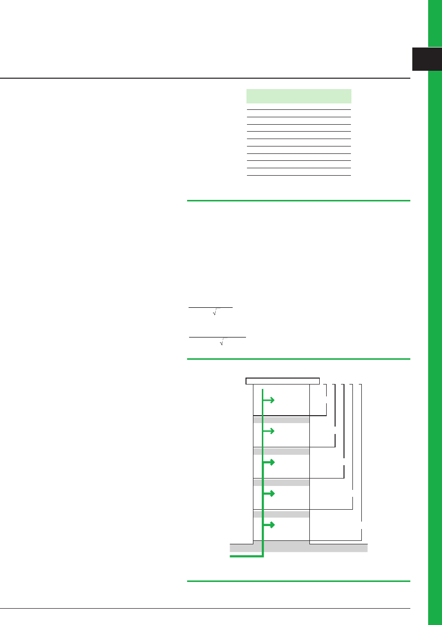
Example (see Fig. A):
5 storeys apartment building with 25 consumers, each having 6 kVA of installed load.
The total installed load for the building is: 36 + 24 + 30 + 36 + 24 = 150 kVA
The apparent-power supply required for the building is: 150 x 0.46 = 69 kVA
From Figure A10, it is possible to determine the magnitude of currents in different
sections of the common main feeder supplying all floors. For vertical rising mains
fed at ground level, the cross-sectional area of the conductors can evidently be
progressively reduced from the lower floors towards the upper floors.
These changes of conductor size are conventionally spaced by at least 3-floor
intervals.
In the example, the current entering the rising main at ground level is:
150 x 0.46 x 10
400 3
3
= 100 A
the current entering the third floor is:
(36 + 24) x 0.63 x 10
400 3
3
= 55 A
4
th
floor
6 consumers
36 kVA
3
rd
floor
2
nd
floor
1
st
floor
ground
floor
4 consumers
24 kVA
6 consumers
36 kVA
5 consumers
30 kVA
4 consumers
24 kVA
0.78
0.63
0.53
0.49
0.46
Fig. A11
: Application of the factor of simultaneity (ks) to an apartment block of 5 storeys
4 Power loading of an installation
Fig. A10
: Simultaneity factors in an apartment block
Number of downstream Factor of
consumers
simultaneity (ks)
2 to 4
1
5 to 9
0.78
10 to 14
0.63
15 to 19
0.53
20 to 24
0.49
25 to 29
0.46
30 to 34
0.44
35 to 39
0.42
40 to 49
0.41
50 and more
0.40

Schneider Electric - Electrical installation guide 2008
A - General rules of electrical installation design
A8
© Schneider Electr
ic - all r
ights reser
ved
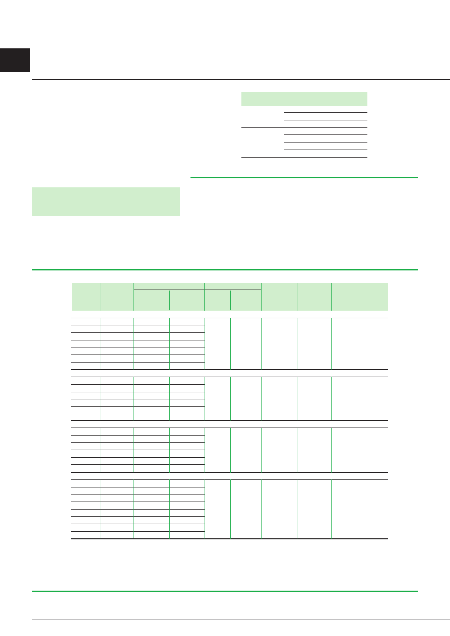
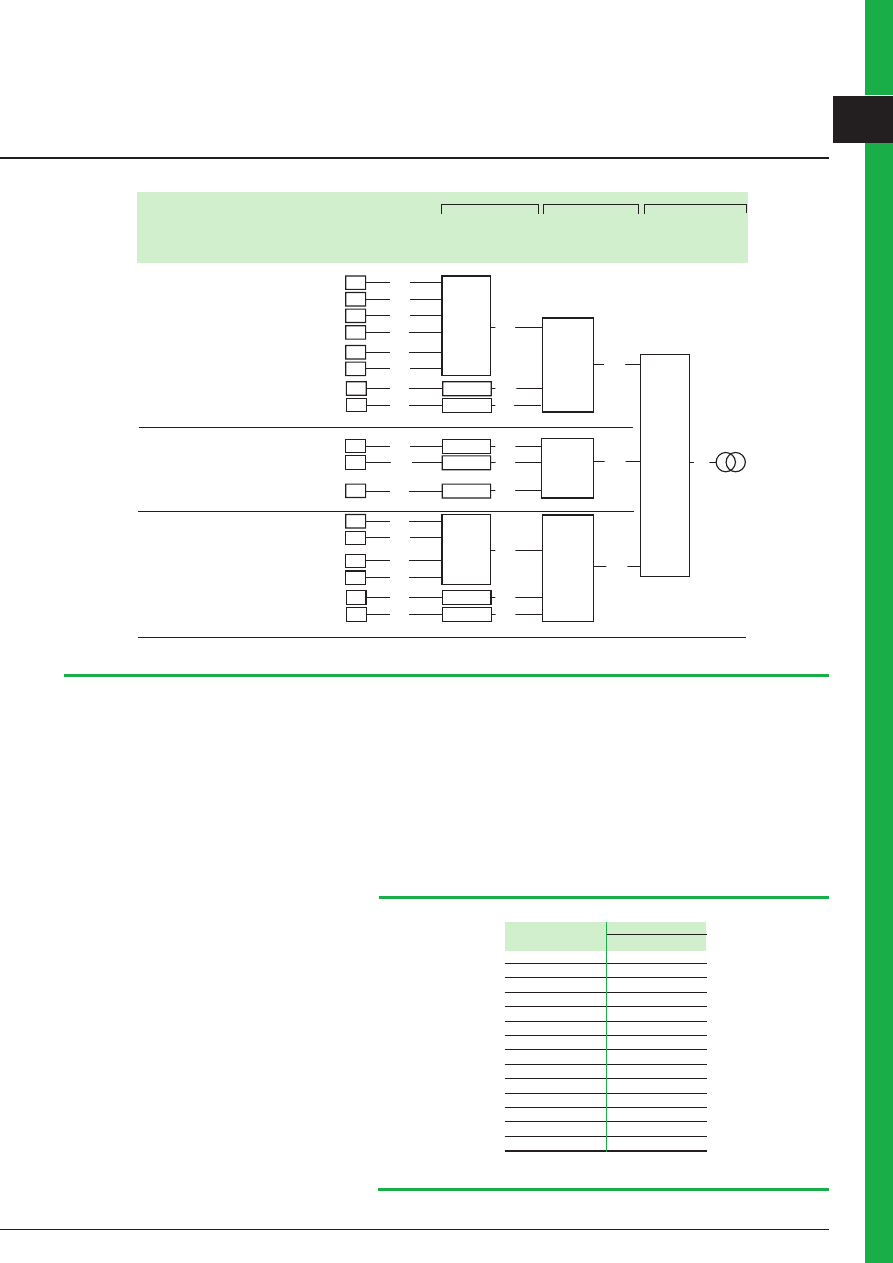
4.4 Example of application of factors ku and ks
An example in the estimation of actual maximum kVA demands at all levels of an
installation, from each load position to the point of supply is given
Fig. A4 (opposite
page).
In this example, the total installed apparent power is 126.6 kVA, which corresponds
to an actual (estimated) maximum value at the LV terminals of the MV/LV transformer
of 65 kVA only.
Note: in order to select cable sizes for the distribution circuits of an installation, the
current
I
(in amps) through a circuit is determined from the equation:
I
=
kVA
U
x 10
3
3
where kVA is the actual maximum 3-phase apparent-power value shown on the
diagram for the circuit concerned, and U is the phase to- phase voltage (in volts).
4.5 Diversity factor
The term diversity factor, as defined in IEC standards, is identical to the factor of
simultaneity (ks) used in this guide, as described in 4.3. In some English-speaking
countries however (at the time of writing) diversity factor is the inverse of ks i.e. it is
always u 1.
Factor of simultaneity for distribution boards
Figure A2 shows hypothetical values of ks for a distribution board supplying a
number of circuits for which there is no indication of the manner in which the total
load divides between them.
If the circuits are mainly for lighting loads, it is prudent to adopt ks values close to
unity.
Fig. A12
: Factor of simultaneity for distribution boards (IEC 60439)
Circuit function
Factor of simultaneity (ks)
Lighting
1
Heating and air conditioning
1
Socket-outlets
0.1 to 0.2
(1)
Lifts and catering hoist
(2)
b
For the most powerful
motor
1
b
For the second most
powerful motor
0.75
b
For all motors
0.60
(1) In certain cases, notably in industrial installations, this factor can be higher.
(2) The current to take into consideration is equal to the nominal current of the motor,
increased by a third of its starting current.
Fig. A13
: Factor of simultaneity according to circuit function
Number of
Factor of
circuits
simultaneity (ks)
Assemblies entirely tested 0.9
2 and 3
4 and 5
0.8
6 to 9
0.7
10 and more
0.6
Assemblies partially tested 1.0
in every case choose
Factor of simultaneity according to circuit function
ks factors which may be used for circuits supplying commonly-occurring loads, are
shown in
Figure A3.
4 Power loading of an installation
Schneider Electric - Electrical installation guide 2008
A - General rules of electrical installation design
A9
© Schneider Electr
ic - all r
ights reser
ved
4 Power loading of an installation
Fig A14
: An example in estimating the maximum predicted loading of an installation (the factor values used are for demonstration purposes only)
1
Distribution
box
Workshop A
5
0.8
0.8
0.8
0.8
0.8
0.8
5
5
5
2
2
Lathe
18
3
1
1
1
0.8
0.4
1
15
10.6
2.5
2.5
15
15
Ventilation
0.28
1
18
1
1
2
1
Oven
30 fluorescent
lamps
Pedestal-
drill
Workshop B Compressor
Workshop C
no. 1
no. 2
no. 3
no. 4
no. 1
no. 2
no. 1
no. 2
no. 1
no. 2
4
4
4
4
1.6
1.6
18
3
14.4
12
1
1
1
1
2.5
2
18
15
15
2.5
Workshop A
distribution
box
0.75
Power
circuit
Power
circuit
Powver
circuit
Workshop B
distribution
box
Workshop C
distribution
box
Main
general
distribution
board
MGDB
Socket-
oulets
Socket-
oulets
Socket-
oulets
Lighting
circuit
Lighting
circuit
Lighting
circuit
0.9
0.9
0.9
0.9
10.6
3.6
3
12
4.3
1
15.6
18.9
37.8
35
5
2
65
LV / MV
Distribution
box
1
1
1
0.2
1
10/16 A
5 socket-
outlets
20 fluorescent
lamps
5 socket-
outlets
10 fluorescent
lamps
3 socket-
outlets
10/16 A
10/16 A
Utilization
Apparent Utilization Apparent Simultaneity Apparent Simultaneity Apparent Simultaneity Apparent
power
factor
power
factor
power
factor
power factor
power
(Pa)
max.
demand
demand
demand
demand
kVA
max. kVA
kVA
kVA
kVA
Level
Level 2
Level 3
4.6 Choice of transformer rating
When an installation is to be supplied directly from a MV/LV transformer and
the maximum apparent-power loading of the installation has been determined, a
suitable rating for the transformer can be decided, taking into account the following
considerations (see
Fig. A5):
b
The possibility of improving the power factor of the installation (see chapter L)
b
Anticipated extensions to the installation
b
Installation constraints (e.g. temperature)
b
Standard transformer ratings
Fig. A15
: Standard apparent powers for MV/LV transformers and related nominal output currents
Apparent power
I
n (A)
kVA
237 V
40 V
100
244
141
160
390
225
250
609
352
315
767
444
400
974
563
500
1218
704
630
1535
887
800
1949
1127
1000
2436
1408
1250
3045
1760
1600
3898
2253
2000
4872
2816
2500
6090
3520
3150
7673
4436

Schneider Electric - Electrical installation guide 2008
A - General rules of electrical installation design
A20
© Schneider Electr
ic - all r
ights reser
ved
The nominal full-load current
I
n on the LV side of a 3-phase transformer is given by:
I
n
a x 10
3
=
P
U 3
where
where
b
Pa = kVA rating of the transformer
b
U = phase-to-phase voltage at no-load in volts (237 V or 410 V)
b
I
n is in amperes.
For a single-phase transformer:
I
n
a x 10
3
=
P
V
where
where
b
V = voltage between LV terminals at no-load (in volts)
Simplified equation for 400 V (3-phase load)
b
I
n = kVA x 1.4
The IEC standard for power transformers is IEC 60076.
4.7 Choice of power-supply sources
The importance of maintaining a continuous supply raises the question of the use of
standby-power plant. The choice and characteristics of these alternative sources are
part of the architecture selection, as described in chapter D.
For the main source of supply the choice is generally between a connection to the
MV or the LV network of the power-supply utility.
In practice, connection to a MV source may be necessary where the load exceeds
(or is planned eventually to exceed) a certain level - generally of the order of
250 kVA, or if the quality of service required is greater than that normally available
from a LV network.
Moreover, if the installation is likely to cause disturbance to neighbouring consumers,
when connected to a LV network, the supply authorities may propose a MV service.
Supplies at MV can have certain advantages: in fact, a MV consumer:
b
Is not disturbed by other consumers, which could be the case at LV
b
Is free to choose any type of LV earthing system
b
Has a wider choice of economic tariffs
b
Can accept very large increases in load
It should be noted, however, that:
b
The consumer is the owner of the MV/LV substation and, in some countries,
he must build and equip it at his own expense. The power utility can, in certain
circumstances, participate in the investment, at the level of the MV line for example
b
A part of the connection costs can, for instance, often be recovered if a second
consumer is connected to the MV line within a certain time following the original
consumer’s own connection
b
The consumer has access only to the LV part of the installation, access to the
MV part being reserved to the utility personnel (meter reading, operations, etc.).
However, in certain countries, the MV protective circuit-breaker (or fused load-break
switch) can be operated by the consumer
b
The type and location of the substation are agreed between the consumer and
the utility
4 Power loading of an installation
Document Outline
- Cover
- Foreword
- The Guiding System
- General contents
- Chapter A : General rules of electrical installation design
- 1 Methodology
- 2 Rules and statutory regulations
- 2.1 Definition of voltage ranges
- 2.2 Regulations
- 2.3 Standards
- 2.4 Quality and safety of an electrical installation
- 2.5 Initial testing of an installation
- 2.6 Periodic check-testing of an installation
- 2.7 Conformity (with standards and specifications) of equipment used in the installation
- 2.8 Environment
- 3 Installed power loads - Characteristics
- 4 Power loading of an installation
- Chapter B : Connection to the MV utility distribution network
- Chapter C : Connection to the LV utility distribution network
- Chapter D : MV & LV architecture selection guide
- Chapter E : LV Distribution
- Chapter F : Protection against electric shocks
- Chapter G : Sizing and protection of conductors
- Chapter H : LV switchgear: functions & selection
- Chapter J : Protection against voltage surges in LV
- Chapter K : Energy Efficiency in electrical distribution
- Chapter L : Power factor correction and harmonic filtering
- Chapter M : Harmonic management
- Chapter N : Characteristics of particular sources and loads
- Chapter P : Residential and other special locations
- Chapter Q : EMC guidelines
- Back cover
Wyszukiwarka
Podobne podstrony:
Make Wearable Electronics Design 2014
Make Wearable Electronics Design 2014
Embedded Systems Electronic Design Magazine
Electrolux sprzęt
Biomass Fired Superheater for more Efficient Electr Generation From WasteIncinerationPlants025bm 422
History Costume History Costume Design Viking Women
General Electric
Rodzaje pracy silników elektrycznych, 04. 01. ELECTRICAL, 07. Elektryka publikacje, 07. Electrical M
Eurocode 5 EN 1995 1 1 Design Of Timber Structures Part 1 1 General Rules
Elektor Electronics No 10 10 2011
ElectronIII
Electrolysis (8)
Electronics 4 Systems and procedures S
DSC EcoCup Electric Vacuum Cup Flyer
Electrochemical properties for Journal of Polymer Science
[Instrukcja] GDOT Design Policy Manual Chapter 8 Roundabouts (USA)
58 SPECIFICATIONS & ELECTRIC COOLING FANS
100108 nmea 0183 sentences not recommended for new designs
więcej podobnych podstron