MAR.
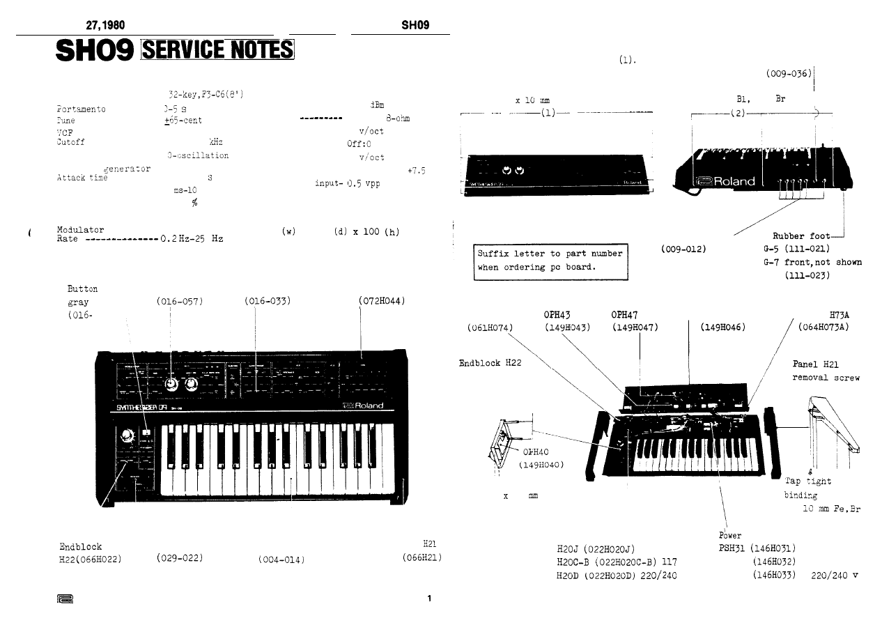
SPECIFICATIONS
Keyboard ----------
--------
range --------
frequency -- 10 Hz-20
Resonance ---------
Envelope
------- 1 x3-2.5
Decay time -------- 2
s
Sustain level ----- O-100
Release time ------ 2 ms-10 s
Delay time -------- O-l.5 s
Jacks
Signal output --
Phones
cv output ------
Gate output ----
CV input -------
Gate input -----
Ext. sig.
-10
Stereo
1
v: On;+14 v
1
Threshold:
v
or less
Power consumption -- 8-watt
Weight --------- 6.1 kg
Dimensions
605
x 305
mm
no.8
Knob no.57
Knob no.33
Panel H44
-008)
Bender unit
Keyboard X132-F
Side panel
PS-4
R-L set
Roland
Printed in Japan A3
Panel H44 removal screws:
(2)
Jack SG7713 no.4 stereo
'Tap tight binding head
Self tapping binding head
3
Fe,Br
3 x 6 mm
Fe,
Jack SG7622 no.8
Chassis H74
OPH46 (not shown)
Holder
removal screw
Binding head
3 x 6 mm Fe,Br
Tap tight binding
3 10
Fe,Br
head
3
x
Power transformer
supply board
100 v
100 v
v
PSH32
117 v
v
PSH33
MAR.
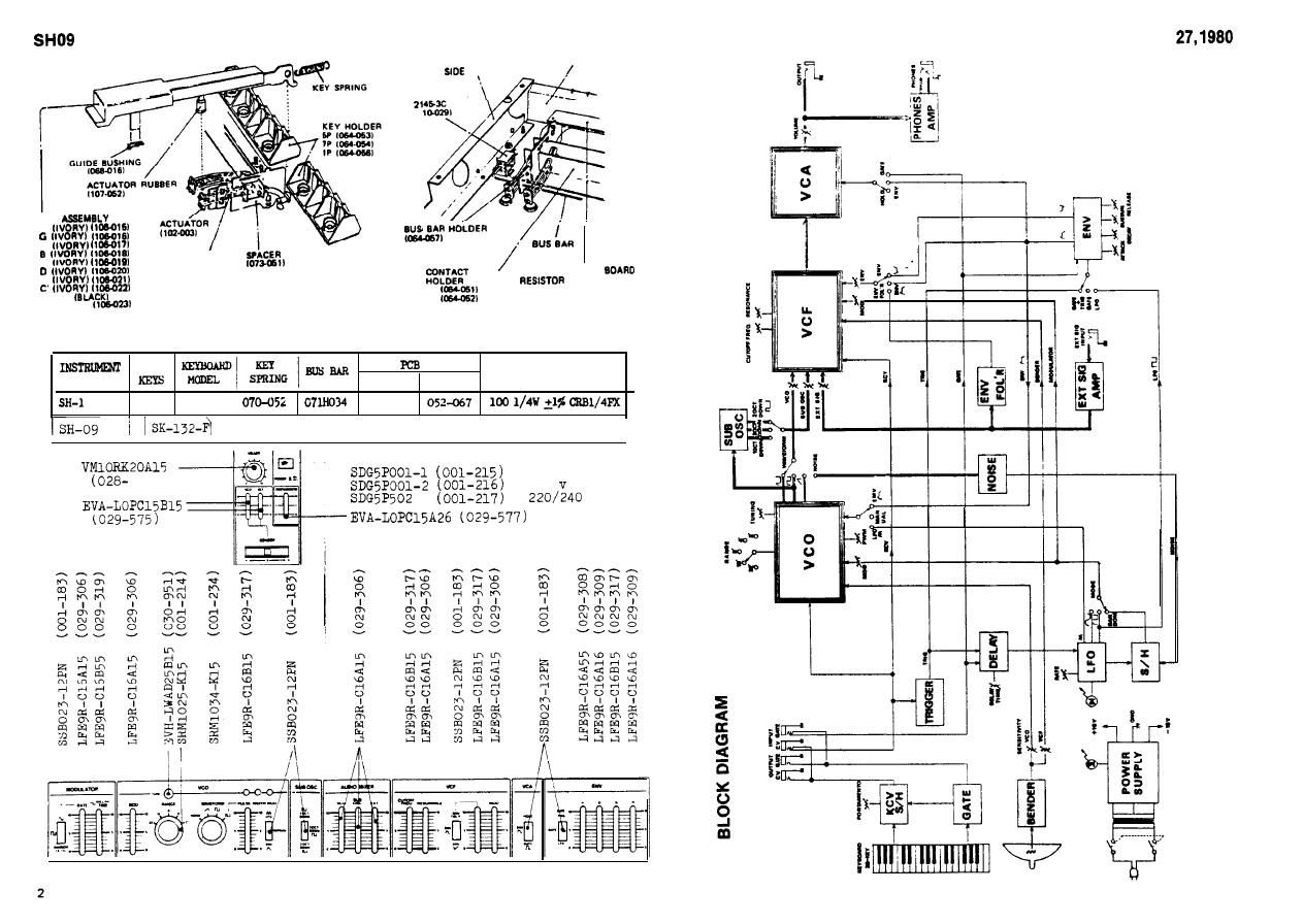
KEY
F
A
CONTACT LEAF
c
ion.0011
E
SHARP
KEYBOARD PARTS
CHASSIS
ANGLE
CONNECTOR
IO
.
LEAF
PRINTED CIRCUIT
6P
7P
MODEL
6 P
7 P
M O D E L
RESISTOR
32
SK-132-D
052-066
32
identical to SK-132D except for blind
I
7 0 6 )
Power switch
100 v
117
v
!
MAR.
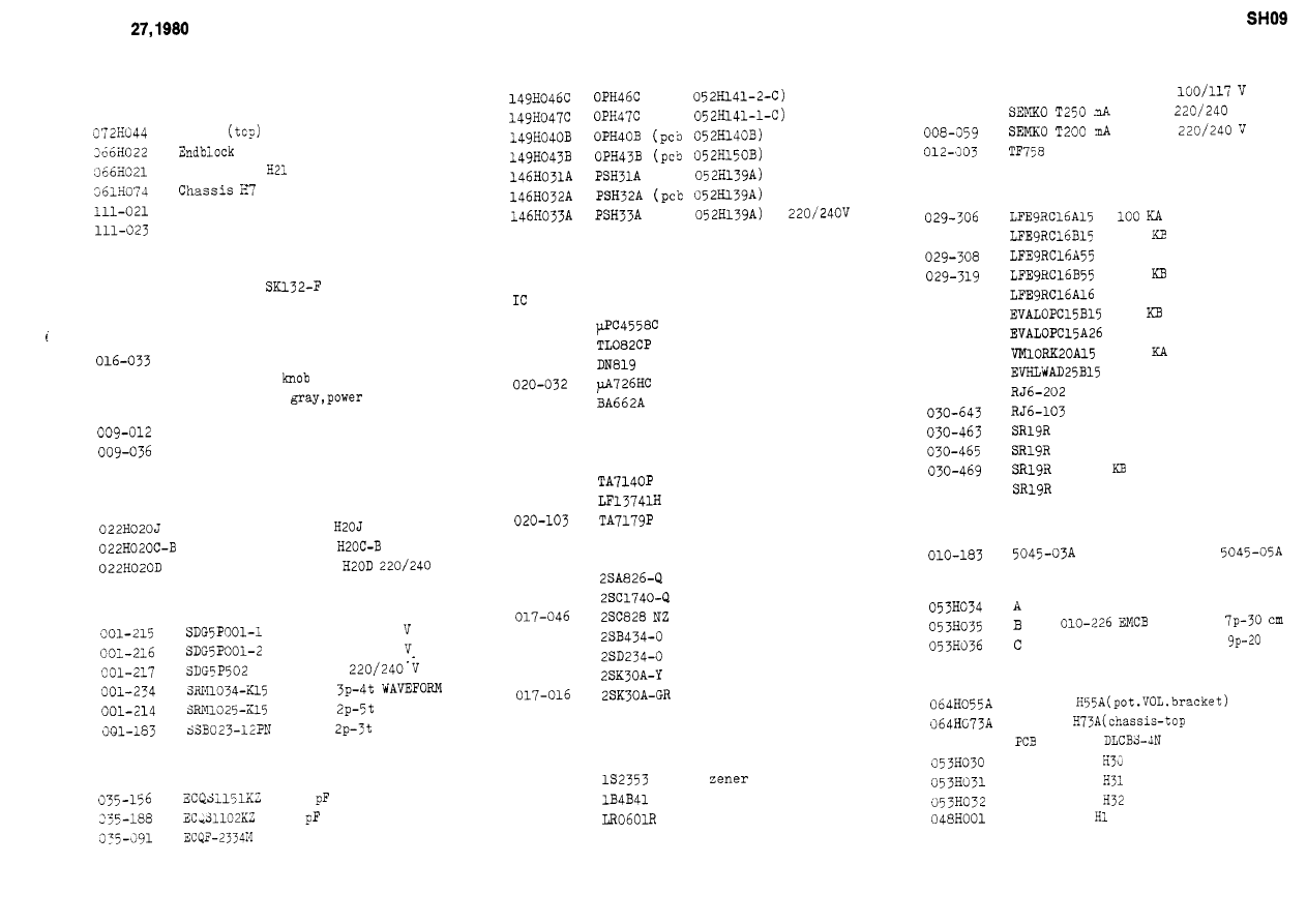
PARTS LIST
Panel
H44
(bender) H22
Side panel
a pair of R and L
4
Foot G-5
rear
Foot G-7
front
068-020
Bushing no.20
panel
004-014
029-022
016-057
063-012
016-008
068-005
068-018
Keyboard
Bender assy PB-4
Knob no.57 rotary
Knob no.33 slider
Strip no.12
no.33
Button no.8
switch
Jack SG7622 no.8 mono
Jack SG7713 no.4 stereo
Bushing no.5
jack
Bushing no.18 red,jack
Power transformer
100 v
Power transformer
117 V
Power transformer
V
SWITCH
power
100
power
117
power
rotary
rotary
RANGE
slide
CAPACITOR
150 polystyrene
1000
polystyrene
0.33 mfd polypropylene
PCB ASSEMBLY
(pcb
(pcb
(pcb
100 v
117 V
(pcb
SEMICONDUCTOR
020-097
020-100
020-039
020-160
0 2 0 - 1 8 9
020-102
TRANSISTOR
017-097
017-118
017-022
017-010
017-014
DIODE
018-014
132473
018-078
018-089
019-009
(noise generator)
FET
FET
rectifier stack
LED
FUSE. FUSE HOLDER
0 0 8 - 0 2 9
MGP 0.25 A prim.
008-060
prim.
V
sec.
fuse clip
P
OTENTIOMETER
slide
029-317
100
slide
500 KA slide
500
slide
029-309
1 MA
slide
029-575
100
slide
029-577
2 MA
slide
028-706
100
rotary
030-951
100 KB rotary
030-641
2 KB trimmer, metal film
10 KB trimmer, metal film
4.7 KB trimmer
10 KB trimmer
47
trimmer
030-471
100 KB trimmer
WAFER TERMINAL. WIRING ASSEMBLY
Terminal
010-186
010-218
EMCS 0750
010-220
EMCS 0950
Wiring assy
0730851
010-228 EMCB 0920851
cm
OTHERS
Holder
Holder
panel)
064-264
holder
Flat cable
Flat cable
Flat cable
Heat sink
MAR.
I
4
MAR.
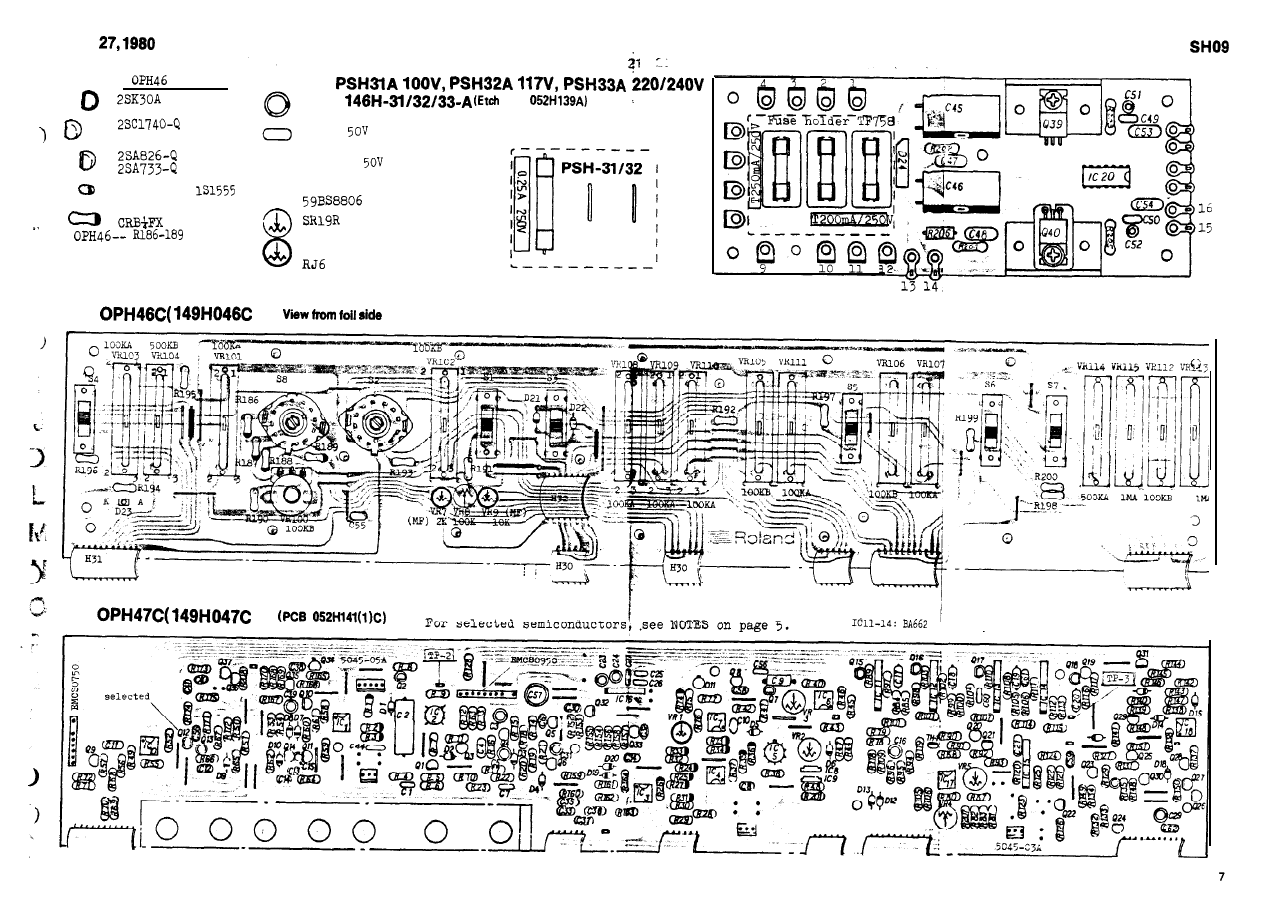
OPH46
o x i d e f i l m .
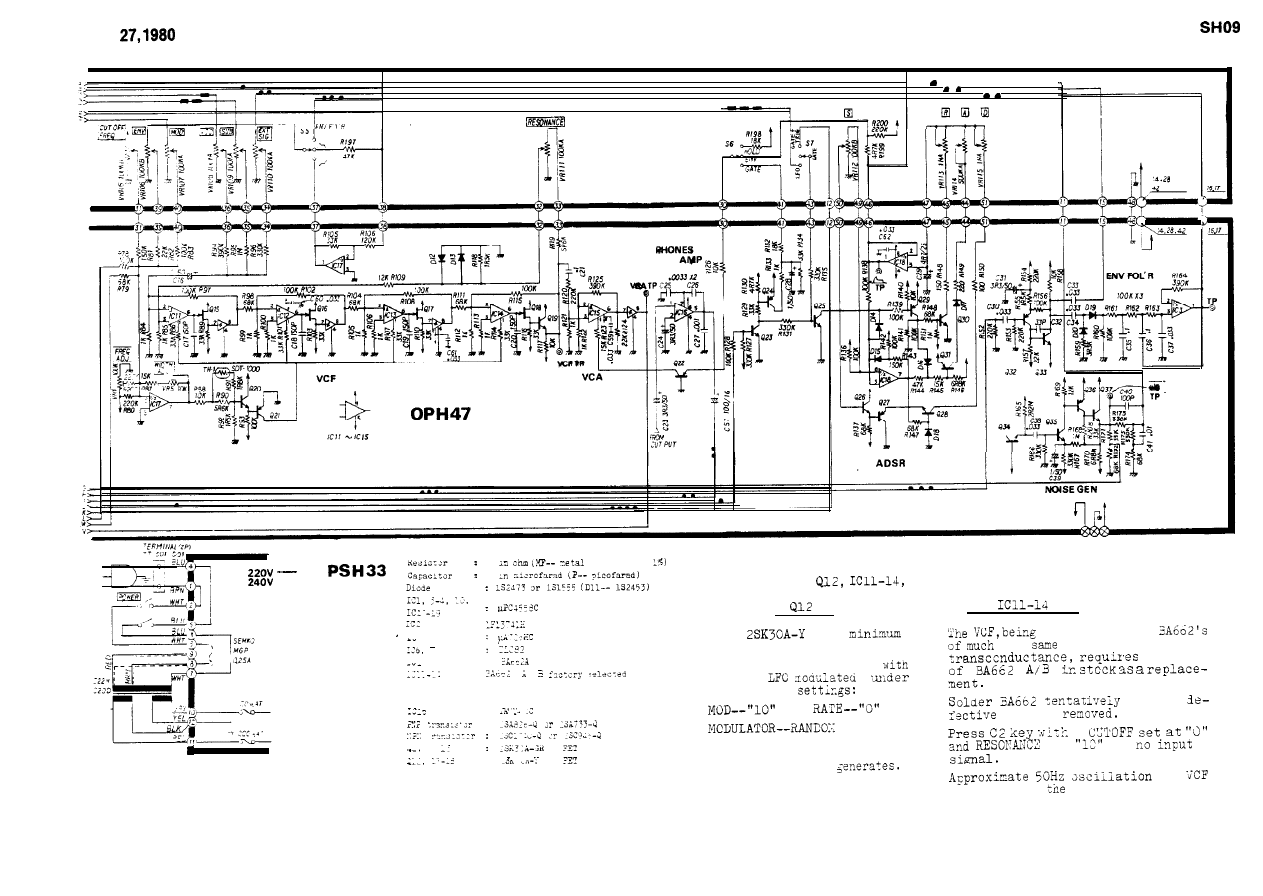
NOTES -- Replacing Selected IC, Transistor --
----
When
replacing
take tae following
procedures.
. .
Choose
for
a set of four
leakage.
the
characteristics in
test
:
Check new Q12 for leakage
a
VCO being
the foilowing
after
:
one is
:
at
--
VCO should not drift before
:
tne next d/H pulse
at
stage proves
IC adeqate.
5
MAR.
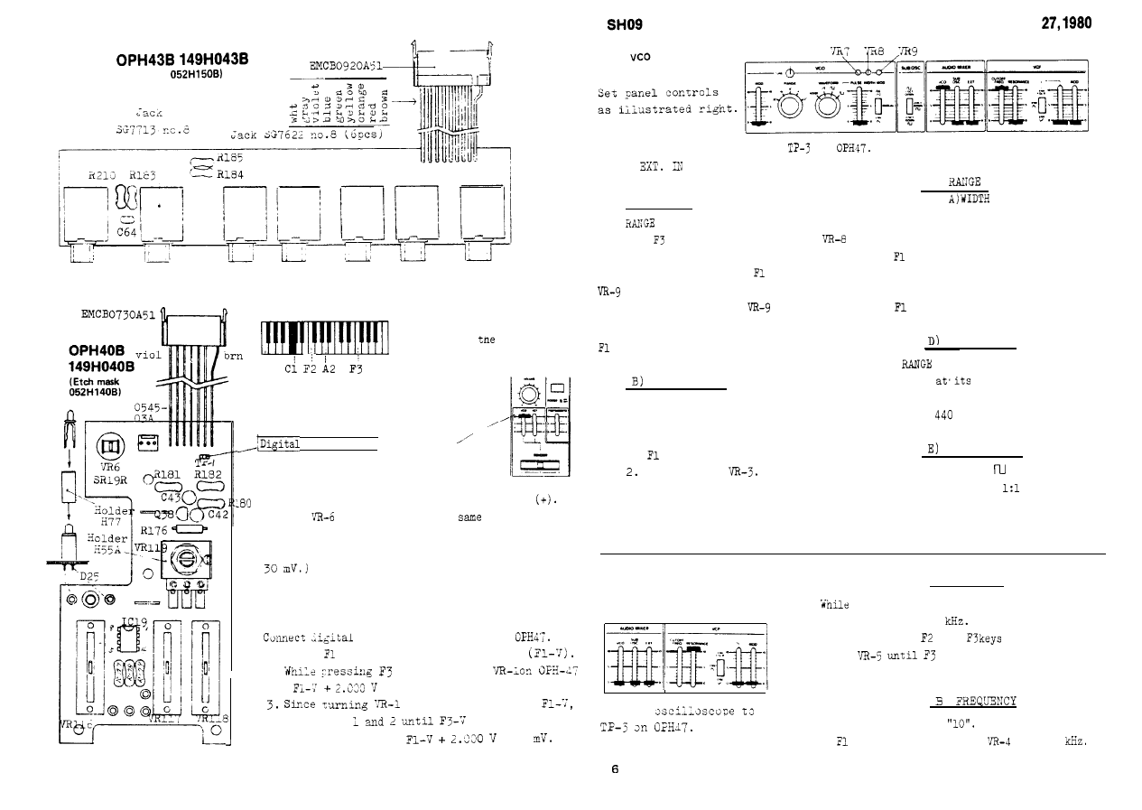
(Etch mask
View from the foil side
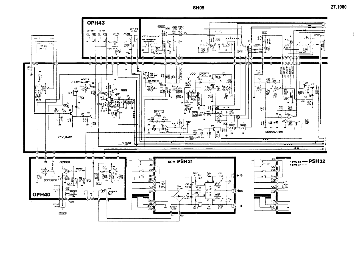
ADJUSTMENT
Fl
KEY DESIGNATION
only for
adjustments
BENDER
Panel setting and connection:,,-
voltmeter!
at 10
1. Flip and hold Bender lever
at
the left(-). Note the reading.
2. Turn and hold the lever at the right
Adjast
on OPH40 for the
reading, but
opposite polarity, as in step 1.
(Difference between two readings must be within
KCV
voltmeter to TP-2 on
1. Press
key and note the reading,
2.
key, adjust
for
reading.
has an effect on
repeat steps
becomes
+ 1
Connect an oscilloscope to
on
Apply reference F note to the
scope
for Lissajous figures.
A) 'WIDTH
Set
at 8'.
1. With
key held down, adjust
for motionless figures.
2. While pressing down
key, adjust
for motionless figures.
F3 pitch will vary as
turned.
3. Repeat steps 1 and 2 until F3 and
figures stand still.
LINEARITY
-- details follow A) WIDTH --
Set RANGE at 2'.
Adjust the pots.
1.
key --- VR-8.
F3 key ---
3. Repeat steps 1 and 2.
Adjustments A and B must be repeated
C)
--refer to
for details--
Set RANGE at 32'.
Obtain stable Lissajous figures.
1.
key --- VR-8.
Place RANGE at 2'.
Obtain motionless figures.
1.
key --- W-7.
FREQUENCY
Set
at 8'.
Set TUNE
midpoint.
1. While playing A2 key,adjust
I
VR-8 for
Hz.
DUTY CYCLE
because of cross interference between them.
Set WAVEFORM at
.
1. Adjust VR-2 for
mark/space.
VCF
A) WIDTH
Set Controls as shown below.
1.
pressing A2 key, set CUTOFF FREQ.
for approximate 1
2. While playing
and
alternateiy,
turn
figure doubles F2 in
cycle.
Connect
Slide up CUTOFF knob to
1. With
key held down, set
for 20
MAR.
OPH47
or
2X945-4
or
152473 or
Metal
oxide film
:
tailored for nearly
equal resistance
0
0
ECEA
mask
Mylar
K
5
6
Ceramic
K
Check point
7
8
Metal film
)
2c
19
18
17
)
selected.
Wyszukiwarka
Podobne podstrony:
Roland Jet Phaser AP 7 Service Manual
hplj 5p 6p service manual vhnlwmi5rxab6ao6bivsrdhllvztpnnomgxi2ma vhnlwmi5rxab6ao6bivsrdhllvztpnnomg
Oberheim Prommer Service Manual
Korg SQ 10 Service Manual
MAC1500 service manual
Kyocera Universal Feeder UF 1 Service Manual
Proview RA783 LCD Service Manual
indesit witp82euy Service Manual
Glow Worm installation and service manual Hideaway 70CF UIS
Proview PZ456 LCD Service Manual
Glow Worm installation and service manual Ultimate 50CF UIS
ewm2000 service manual
Glow Worm installation and service manual Ultimate 60CF UIS
Proview SH770I LCD Service Manual
M23 Service Manual
Glow Worm installation and service manual Glow micron 60
Konica Minolta QMS 7115, 7118 Service Manual
Honda NSR125 '87 Service Manual
więcej podobnych podstron