Fitting Instructions /Inbouwinstructie /Manuel de Montage / Einbauanleitung
Fitting Instructions /Inbouwinstructie /Manuel de Montage / Einbauanleitung
684200-010*1
1/10
www.teleflexgfi.nl
02-08-2006
Opel Meriva Z16XEP MT/AT ‘06--->
When installing the LPG installation,compliance is required with the following guidelines:
*
This manual is based on dutch regulations. It’s the installer’s responsibility to check the local regulations and to
make all necessary adaptions
*
Before commencing the installation of the LPG installation, remove the negative terminal from the battery.
*
If necessary, consult the workshop manual of the relevant car before the parts are disassembled.
*
All directions in the installation manual are given from the direction of the traffic.
*
Unless indicated otherwise, all measurements are in mm.
*
When drilling be careful for the underlying parts!
*
Deburr holes in the plating and treat them for rust.
*
First check the measurements given and the wire colours and positions.
*
The holes for the injectors must be drilled in accordance with the instructions.
Use the correct drilling jig,if indicated.
*
When fitting the injector nipples, vacuum nipples, water nipples, gas nipples and LPG valve, use sealing locking
agent on the screwthread.
*
Mount the GSI injector in line with the injector holder.
*
Always oil the O-rings of the injector holders.
*
Use the right hose clips when fitting all hoses.
*
After installing the LPG installation, ensure a watertight seal on the cable and pipe lead-throughs.
*
Use the connectors supplied for electrical connections and then insulate them completely. Do not solder!
*
Prevent the risk of damage from wiring harnesses and hoses. Fasten them with the cable ties supplied
*
Check the entire installation for leaks once installation is completed.
*
Adjustment for a car with TeleflexGFI LPG installation:
Adjust the operating pressure of the vaporiser/pressure regulator when the engine is at operating temperature:
1st stage: 1000 mbar
This adjustment must always be made immediately after the installation of the LPG installation!
GENERAL INSTRUCTIONS
Bij de inbouw van de autogasinstallatie dienen de volgende richtlijnen in acht te worden genomen:
*
Deze instructie is gebaseerd op de nederlandse inbouwvoorschriften. Het is de verantwoording van de inbouwer om
de lokale regels te controleren en de nodige aanpassingen uit te voeren.
*
Neem voordat met de inbouw van de autogasinstallatie wordt begonnen de minpool van de accu los.
*
Raadpleeg, indien nodig, het werkplaatshandboek van de betreffende auto voordat onderdelen worden
gedemonteerd.
*
Alle richtingen in de inbouwhandleiding zijn aangegeven vanuit de rijrichting.
*
Alle maten zijn, tenzij anders aangegeven, vermeld in mm’s.
*
Let bij het boren op de onderliggende delen.
*
Gaten in het plaatwerk aangebracht ontbramen en tegen roest behandelen.
*
Controleer vooraf de opgegeven maten en draadkleuren en posities.
*
Het boren van de gaten voor de injectoren moet volgens de instructies gebeuren. Indien aangegeven de juiste
boormal gebruiken.
ALGEMENE INSTRUCTIES
Instruction Nr./Instructienr./No. d’instruction/Einbauanleitungs Nr.
Make / Merk / Marque / Marke:
Car-Engine type / Auto-Motor type / Auto-Moteur type / Model-Motor Typ:
Modelyear / Modeljaar / Annee de fabrication / Modelljahr :
Motorkit Nr. / Motorset Nr. / No. Kit moteur / Motorkit Nr. :
684200-010*1
Opel
Meriva Z16XEP
‘06 --->
694200-010

Fitting Instructions /Inbouwinstructie /Manuel de Montage / Einbauanleitung
Fitting Instructions /Inbouwinstructie /Manuel de Montage / Einbauanleitung
684200-010*1
2/10
www.teleflexgfi.nl
02-08-2006
Opel Meriva Z16XEP MT/AT ‘06--->
ALGEMEINE ANWEISUNGEN
Règles de montage de l’installation gaz :
*
Cette manuel d”instruction est bassé sur normes neerlandais. C”est la responsabilité de mechanicien de vér normes
locales !
*
Veuillez déconnecter, avant le montage de l’installation gaz la borne négative de la batterie.
*
Consultez, si nécessaire, le manuel d’atelier de la voiture concernée avant le démontage des pièces.
*
Toutes les indications du manuel de montage sont données suivant l’ordre chronologique des opérations à
effectuer.
*
Toutes les mesures sont, sauf autrement indiquées, en mm.
*
Faites attention aux pièces latérales pendant les perçages.
*
Les trous réalisés dans la tôle doivent être ébavurés et protégés contre la rouille.
*
Contrôler à l’avance les mesures, les couleurs des fils et les positions indiquées.
*
Le perçage des trous pour les injecteurs doit être fait selon l’instruction de montage.
Si indiqué,utiliser le gabarit spécifique.
*
Au montage des raccords injecteurs, raccords à dépression, raccords d’eau, raccords de gaz et
électrovanne principale, utilisez un produit de scellement sur le filet.
*
Toujours utiliser de l’huile sur les joints, en montant les injecteurs.
*
Placer l’injecteur GSI précisément dans l’axe de sa coupelle et sans contrainte.
*
Serrer les tuyaux avec les colliers correspondant aux diamètres.
*
Après le montage, assurer l’étanchéité des passages faisceaux et canalisations.
*
Réaliser les connections électriques avec les connecteurs livrés et puis isoler. Ne pas souder!
*
Attachez les faisceaux, câbles et tuyaux pour éviter tous frottements.
*
Après le montage, contrôler l’étanchéité gaz, essence et eau sur tous les circuits et raccords.
*
Règlage de l’ installation TeleflexGFI:
Règler la pression de travail du détendeur quand la voiture est en température de fonctionnement.
Première étage: 1000 mbar
Ce règlage doit être effectué directement après le montage de l’installation gaz!
Die folgenden Richtlinien müssen beim Einbau einer Autogasanlage befolgt werden:
*
Diese Anweisungen richten sich nach der niederländischen Einbauvorschriften. Es unterliegt der alleinigen
Verantwortung des Installateurs um die örtlichen Regeln zu kontrollieren und die erforderlichen Anpassungen
auszuführen.
*
Vor dem Einbau der Autogasanlage den Minuspol der Batterie abklemmen.
*
Falls erforderlich, vor dem Ausbau von Fahrzeugteilen zuerst im diesbezüglichen Werkstatthandbuch nachschlagen.
*
Alle Richtungsanweisungen in dieser Einbauanleitung beziehen sich auf die Fahrtrichtung.
*
Sofern nicht anders vermerkt, sind alle Maße in mm angegeben.
*
Beim Bohren auf die unterliegenden Teile achten.
*
In den Blechplatten gebohrten Löcher entgraten und gegen Rost behandeln.
*
Die angegebenen Maße, Drahtfarben und Positionen vor dem Einbau kontrollieren.
*
Beim Anbringen von Bohrlöchern für die Injektoren müssen die Anweisungen streng befolgt werden.
Falls angegeben, die korrekte Bohrschablone verwenden.
*
Zum Abdichten der Injektor-, Unterdruck-, Wasser- und Gasnippel sowie des LPG-Ventils, beim Einbau auf dem
Schraubengewinde ein Dichtmittel anbringen.
*
Den GSI-Injektor auf einer Linie mit dem Injektorhalter einbauen.
*
Die O-Ringe der Injektorhalter immer mit Öl benetzen.
*
Für alle Schläuche die passenden Schlauchklemmen verwenden.
*
Nach dem Einbau der Autogasanlage die Kabel- und Leitungsdurchführung wasserdicht abdichten.
*
Für die elektrischen Anschlüsse die mitgelieferten Steckverbinder verwenden und danach abisolieren. Nicht löten!
*
Kabelbäume und Schläuche vor Beschädigungen schützen. Diese mit den mitgelieferten Kabelbindern befestigen.
*
Nach dem Einbau die gesamte Anlage auf Lecks überprüfen.
*
Einstellen von Fahrzeugen mit TeleflexGFI Autogasanlagen:
Den Betriebsdruck des Verdampfers/Druckreglers einstellen, wenn der Motor die Betriebstemperatur aufweist:
1. Stufe: 1000 mbar
Diese Einstellungen müssen immer unmittelbar nach dem Einbau der Autogasanlage durchgeführt werden!
INSTRUCTIONS GENERAL
*
Bij de montage van de injectornippels,vacuumnippels,waternippels,gasnippels en LPG-afsluiter een afdichtend
borgmiddel op de schroefdraad gebruiken.
*
Monteer de GSI-injector in lijn met de injectorhouder.
*
Gebruik altijd olie op de O-ringen van de injectorhouders.
*
Alle slangen monteren met de juiste slangklemmen.
*
Na inbouw van de autogasinstallatie de kabel- en leidingdoorvoer waterdicht afwerken.
*
Electrische verbindingen uitvoeren met de bijgeleverde verbindingconnectors en daarna afisoleren. Niet solderen!
*
Voorkom dat kabelbomen en slangen kunnen beschadigen. Leg deze vast met de bijgeleverde binders
*
Controleer de gehele installatie op lekkage als de inbouw gereed is.
*
Afstelling voor auto met TeleflexGFI autogasinstallatie:
Stel de werkdruk van de verdamper/drukregelaar af als de motor op bedrijfstemperatuur is.
1e trap : 1000 mbar
Deze afstelling moet altijd direct na inbouw van de autogasinstallatie uitgevoerd worden !

Fitting Instructions /Inbouwinstructie /Manuel de Montage / Einbauanleitung
Fitting Instructions /Inbouwinstructie /Manuel de Montage / Einbauanleitung
684200-010*1
3/10
www.teleflexgfi.nl
02-08-2006
Opel Meriva Z16XEP MT/AT ‘06--->
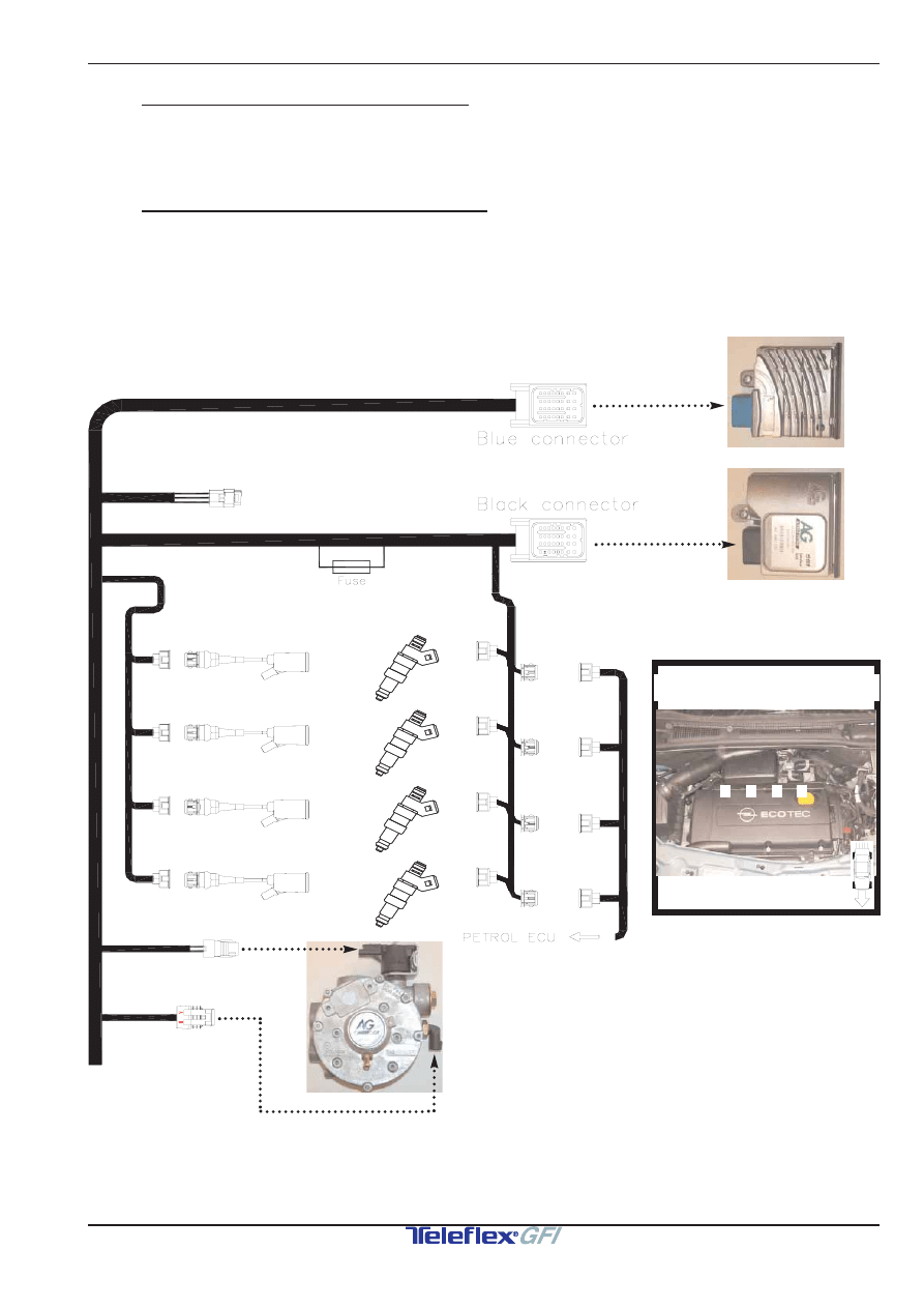
OverviewSystem/SysteemOverzicht/ImplantationGénérale/System Übersicht
Fitting order / Montage volgorde / Ordre de montage / Einbau reihenfolge
Nr.
Description / Omschrijving / Description / Umschreibung
1.
Inlet manifold / Inlaatspruitstuk / Collecteur d’admission/ Ansaugkrumer
2.
GSI-injectors /GSI-injectors /Injecteurs GSI/ GSI-Einspritzventile
3.
Vacuum nipple /Vacuümnippel /Nipple à dépression /Vakuum Nippel
4.
Vaporisor / Verdamper / Vaporiseur / Verdampfer
5
Waterconnexions /Wateraansluitingen /Connections d’eau /Wasseranschlüsse
6.
Filter & Pressure sensor /Filter & Druksensor /
Filtre & capteur de pression / Filter & Drucksensor
7.1
Module Interface unit /Module Interface unit /
Module Unit ‘d interface /Interface Modul
7.2
ECM /ECM /ECM /Steuergerät 600108
8.
Mount connector ECM & Module Interface unit
Monteren connector ECM & Module Interface unit
Monter fiche ECM & Module Unit ‘d interface
Montieren Stecker Steuergerät & Interface Modul
9.
Vacuumconnections / Vacuumaansluitingen /
Connexions de dépression / Vakuumanschlüsse
10.
Electric connections /Electrische aansluitingen
Connexions electriques /Elektronische anschlüsse
Explanation of symbols /Verklaring van symbolen /Explications des symboles /
Kurzzeichnungerklärung
Page 10
Colorcodes/Kleurcodes/Code des coleurs/Farbecodes
Page 10
3
4
7.2
2
2
2
2
7.1
6
8
9
9
9
1
5
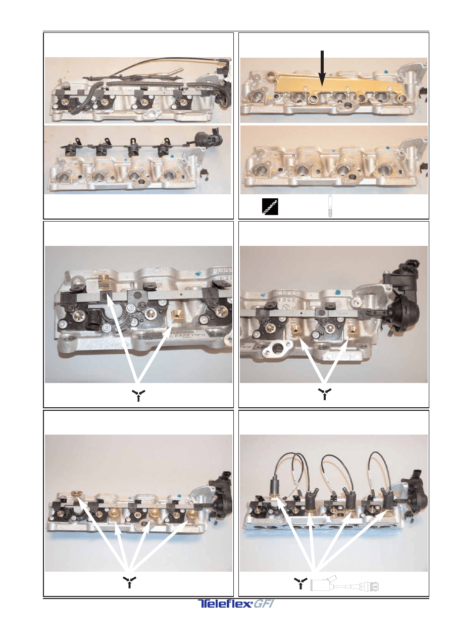
1b
1a
2b
2a
Fitting Instructions /Inbouwinstructie /Manuel de Montage / Einbauanleitung
Fitting Instructions /Inbouwinstructie /Manuel de Montage / Einbauanleitung
2d
2c
684200-010*1
4/10
www.teleflexgfi.nl
02-08-2006
Opel Meriva Z16XEP MT/AT ‘06--->
Ø 8,5 mm
241505-135
M10x1 (4x)
4a
3
4c
4b
Fitting Instructions /Inbouwinstructie /Manuel de Montage / Einbauanleitung
Fitting Instructions /Inbouwinstructie /Manuel de Montage / Einbauanleitung
5b
5a
684200-010*1
5/10
www.teleflexgfi.nl
02-08-2006
Opel Meriva Z16XEP MT/AT ‘06--->
Preparation/Voorbereiding/Préparation/Vorbereitung
600009
244305-542
M8
240008-001
M8
240008-002
M8 x 25
240008-825
600009
M8 x 1
Ø 6.5mm
2x 240008-825
2x 240008-002
2x 240008-001
244305-542
T
19-16-19
T
19-16-19
16-23mm (4x)
12-20mm (4x)
L=400
L=400
Preparation/Voorbereiding/Préparation/Vorbereitung
2x

5d
5c
6b
6a
Fitting Instructions /Inbouwinstructie /Manuel de Montage / Einbauanleitung
Fitting Instructions /Inbouwinstructie /Manuel de Montage / Einbauanleitung
7a
6c
684200-010*1
6/10
www.teleflexgfi.nl
02-08-2006
Opel Meriva Z16XEP MT/AT ‘06--->
(2x)
T
19-16-19(2x)
(2x)
242200-509
(16 mm)
600090 + 4x 50 cm
+
L=400
M6
+
2x
2x
+
242200-509
(8 mm)
600090
7mm
7c
7b
9a
8
Fitting Instructions /Inbouwinstructie /Manuel de Montage / Einbauanleitung
Fitting Instructions /Inbouwinstructie /Manuel de Montage / Einbauanleitung
9c
9b
684200-010*1
7/10
www.teleflexgfi.nl
02-08-2006
Opel Meriva Z16XEP MT/AT ‘06--->
238675-066
238675-066
BLUE
BLACK
600131 + 600108 + 600161
600161
M5 x 20
+
M6
+
Vacuümhose / Vacuümslang
Tuyau de depression / Vakuumschlauch
Ø 5mm + Ø 3.2mm
+ T
6-4-6
AG 35303
ENGINE
MOTOR
MOTEUR
MOTOR
Vacuümhose / Vacuümslang
Tuyau de depression /Vakuumschlauch
Ø 3,2 mm
Vacuümhose / Vacuümslang
Tuyau de depression / Vakuumschlauch
Ø 5 mm
Fitting Instructions /Inbouwinstructie /Manuel de Montage / Einbauanleitung
Fitting Instructions /Inbouwinstructie /Manuel de Montage / Einbauanleitung
684200-010*1
8/10
www.teleflexgfi.nl
02-08-2006
Opel Meriva Z16XEP MT/AT ‘06--->
10a.1 , 10.2 , 10a.3 , 10a.4 , 10a.5 + 10a.6 :
Mount the connectors to the components
Monteer de connectors op de componenten
Monter les connecteurs aux composants
Montiere die Stecker auf die Komponenten
Remark / Opmerking / Remarque / Bemerkung :
Cylinderarrangement equal to data carmanufacturer
Cilindernummering gelijk aan data autofabrikant
Numérotage cylindres égal données fabricant de auto
Numerierung Zylinder nach Hersteller
E
1
A
B
C
D
2
3
4
H
F
G
E
1
A
B
C
D
2
3
4
H
F
G
Cylinder arrangement / Cilindernummering
Numérotage cylindre/ Numerierung Zyl.
4
3
2
1
E
lectrical connections/
E
lectrische aansluitingen/
R
accordement électrique/
E
lektronische anschlüsse
10A
DIAGNOSIS
DIAGNOSE
DIAGNOSTIC
DIAGNOSE
10a.1
(BU)
(BK)
10a.2
10a.3
10a.4
10a.5
10a.6
CYLINDER 4
CYLINDER 3
CYLINDER 2
CYLINDER 1
CYLINDER 4
CYLINDER 1
CYLINDER 3
CYLINDER 2
Connector 4
(Inj. 4)
Connector 3
(Inj. 3)
Connector 2
(Inj. 2)
Connector 1
(Inj. 1)
Fitting Instructions /Inbouwinstructie /Manuel de Montage / Einbauanleitung
Fitting Instructions /Inbouwinstructie /Manuel de Montage / Einbauanleitung
684200-010*1
9/10
www.teleflexgfi.nl
02-08-2006
Opel Meriva Z16XEP MT/AT ‘06--->
E
lectrical connections/
E
lectrische aansluitingen/
R
accordement électrique/
E
lektronische anschlüsse
5.
4.
6.
3.
2.
1.
3.
5.
4.
10b.2
10b.3
10b.4
10b.5
10b.7
REMOVE
STICKER
STICKER
VERWIJDEREN
ENLEVER
AUTOCOLLANT
AUFKLEBER
ENTFERNEN
QUITAR
PEGATINA
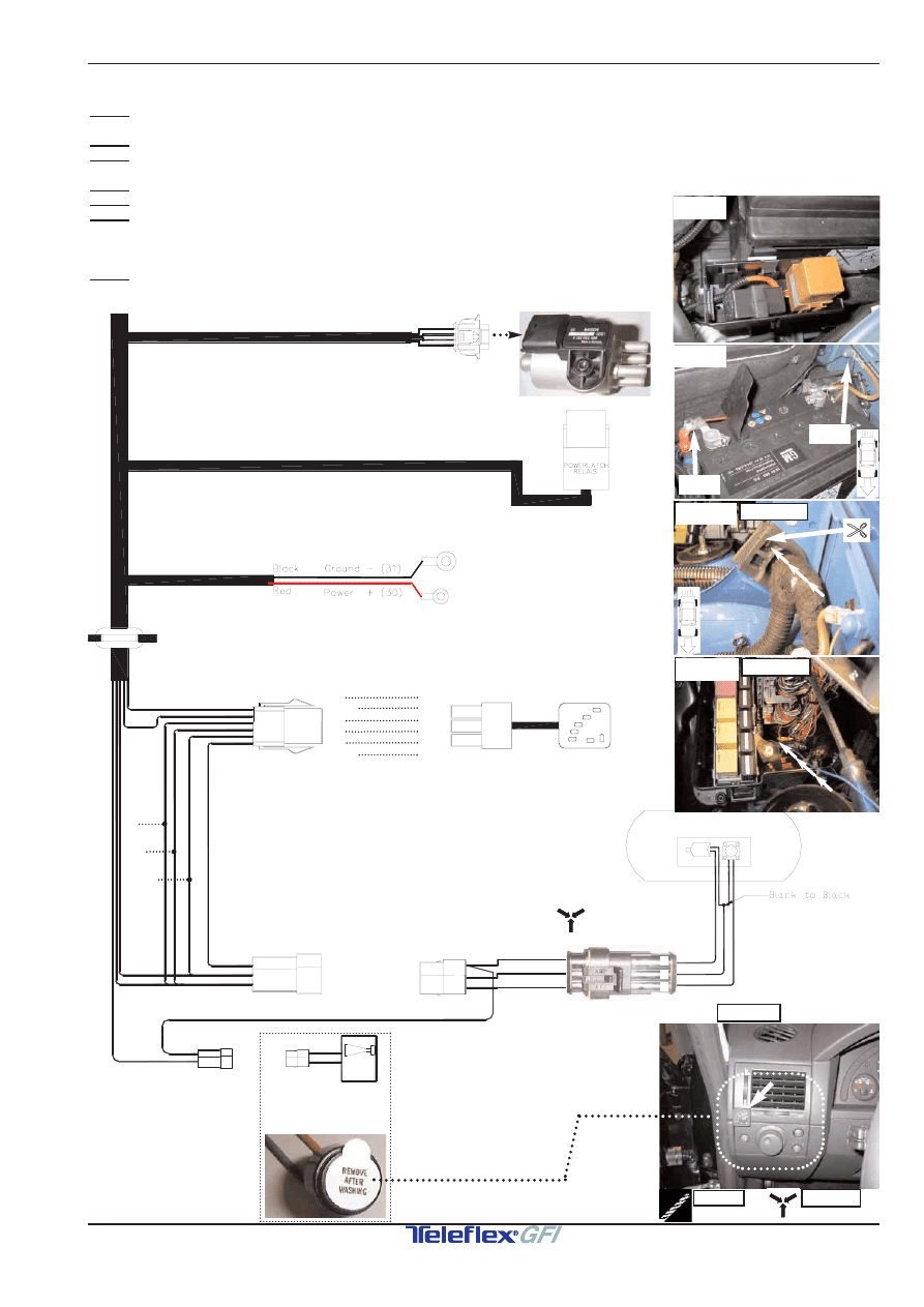
10b.1
Connector Filter & Pressure sensor /Connector Filter & Druksensor /
Fiche Filtre & capteur de pression / SteckerFilter & Drucksensor
10b.2
Power Latch Relais /Power Latch Relais /Power Latch Relais /Power Latch Relais
10b.3
Power (30+) + Ground / Voeding (30+) + Massa /
Alimentation batterie (30+) +Masse /Stromversorgung(30+) + Masse
10b.4
Grummet /Doorvoerrubber /Passe fils caoutchouc /Kabeldurchführungstülle
10b.5
LPG switch / LPG schakelaar / Interrupteur GPL / LPG Schalter
10b.6
Connections to LPG switch + LPG tank/
Aansluitingen schakelaar+ LPG tank /
Connections vers l’interrupteur GPL+ réservoir GPL /
Verbindungen Richtung LPG Schalter + Gastank
10b.7
Beeper(Remove sticker! )/ Alarm(Sticker verwijderen! )/
Alarme(Enlever autocollant!)/ Alarm(Aufkleber Entfernen!)
Ø 8mm
Ø 6mm
10b.1
10B
YE/BN
YE
BK
RD
PU/YE
RD/WH
1
2
3
246400-131
(BROWN)
1.BN
(ORANGE/YELLOW)
2.OR/YE
(YELLOW/BROWN)
3.YE/BN
(PURPLE/YELLOW)
4.PU/YE
(RED/WHITE)
5.RD/WH
(GREEN/YELLOW)
6.GN/YE
10b.6
BN
OR/YE
RD
PU
BK
YE/BN
BN
OR
RD
PU
BK
YE
RD
PU
BK
RD/WH
SWITCH
SWITCH
Ø 8 MM
10b.5
-(31)
GRUMMET
10b.4a
10b.3
10b.2
+(30)
10b.4b
GRUMMET
Fitting Instructions /Inbouwinstructie /Manuel de Montage / Einbauanleitung
Fitting Instructions /Inbouwinstructie /Manuel de Montage / Einbauanleitung
684200-010*1
10/10
www.teleflexgfi.nl
02-08-2006
Opel Meriva Z16XEP MT/AT ‘06--->
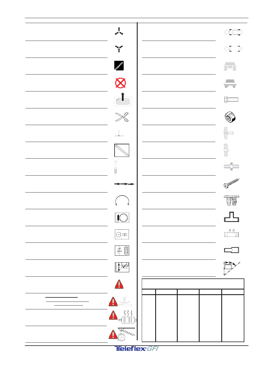
Disassemble part
Demonteer onderdeel
Démonter élément
Teil demontieren
Mount part
Monteer onderdeel
Monter élément
Teil montieren
Drill
Boren
Perforer
Bohren
Redundant part
Te vervallen onderdeel
Pièce d’origine à supprimer
Weggefallen Teil
Piece to be removed from element
Te verwijderen gedeelte van onderdeel
Partie d’origine à supprimer
Teil von Ersatzteil entfernen
Cut
Knippen
Couper
Durchschneiden
Electrical connection
Electrische verbinding
Liaison électrique
Elektrische verbindung
Scriber / Draw
Kraspen / Aftekenen
Pointe à tracer / Dessiner
Reißnadel / Markieren
Use screw tap
Gebruik draadtap
Faire usage de taraudeuse
Gebrauch machen von Gewindeschneiden
Pierce / Moving direction
Doorvoeren / Bewegingsrichting
Guider / Direction mouvement
Durchführen / Bewegungsrichtung
Rotate
Draaien
Tourner
Drehen
Crankshaft signal
Krukas signaal
Signal du vilebrequin
Kurbelwellesignal
Camshaft signal
Nokkenas signaal
Signal de l’ arbre à cames
Nockenwellesignal
Lambda sensor signal
Lambdasonde signaal
Signal de la sonde lambda
Lambdasondesignal
TPS signal
TPS signaal
Signal de la capteur pos. de papillon
Drosselklappensignal
Warning
Let op
Fais attention
Achtung
Attention for hoses/tubes/cables while drilling
Attentie voor leidingen/slangen/kabels met boren
Faites attention pour tubes/tuyau/câbles durante perforer
Achtung fur Leitungen/Schlauchen/Kabel während bohren
Heat! Keep at least 100mm away from source
Hitte! Houd minstens100mm afstand van bron
Chaleur!Tenir au moins 100mmdistance de source
Hitze ! Mindestens 100mm spielraum halten
Moving /Rotating parts
Bewegende / Draaiende delen
Pièces mobile / Giration
Teilen in bewegung / oder drehend
View from top(Indication viewpoint image)
Bovenaanzicht(Indicatie aanzicht foto)
Vue d’ en haut(Indication point de vue photo)
Sicht von Oben (Hinweis Blickpunkt Foto)
View from bottom(Indication viewpoint image)
Onderaanzicht(Indicatie aanzicht foto)
Vue d’ en bas(Indication point de vue photo)
Sicht von Unten (Hinweis Blickpunkt Foto)
Frontview(Indication viewpoint image)
Vooraanzicht(Indicatie aanzicht foto)
Aspect frontal(Indication point de vue photo)
Vorderansicht (Hinweis Blickpunkt Foto)
Rearview(Indication viewpoint image)
Achteraanzicht(Indicatie aanzicht foto)
Aspect arrière(Indication point de vue photo)
Hinteransicht (Hinweis Blickpunkt Foto)
Bolt
Bout
Boulon
Bolzen
Nut (P=plastic)
Moer (P=kunststof)
Écrou (P=plastique)
Mutter (P=Kunststoff)
Original threadend
Origineel draadeind
Boulon fileté d’origine
Gewindestift original
Original threadhole
Bestaand draadgat
Trou taraudé d’origine
Gewindebohrung original
Studbolt
Draadeind
Boulon fileté
Gewinde stift
Screw
Plaatschroef
Vis
Schrauben
Expansion nut
Spreidmoer
Ecrou d’expansion
Spannungsmutter
T-joint water/ vacuum
T-stuk water/ vacuüm
Raccord en T d’eau/ vacuum
T-Stuck Wasser / Vakuum
Water by-pass nipple
Water by-pass nippel
Douille d’eau
Wassernippel
Water extensionpipe
Water verlengnippel
Raccord d’eau
Wasserverlängerung
Bend/Adapt
Buigen/Aanpassen
Courber/Adapter
Biegen/Anpassen
Explanation of symbols /Verklaring symbolen /Explication des symboles /Kurzzeichnung erklärung
100mm
((
(
COLORCODES/KLEURCODES/
CODE DES COLEURS/FARBECODES
BN
BU
GN
YE
GY
PU
PK
RD
WH
BK
OR
CODE
BROWN
BLUE
GREEN
YELLOW
GREY
PURPLE
PINK
RED
WHITE
BLACK
ORANGE
COLOR
KLEUR
COULEUR FARBE
BRUIN
BLAUW
GROEN
GEEL
GRIJS
PAARS
ROZE
ROOD
WIT
ZWART
ORANJE
BRUN
BLEU
VERT
JAUNE
GRIS
VIOLET
ROSE
ROUGE
BLANC
NOIR
ORANGE
BRAUN
BLAU
GRUN
GELB
GRAU
LILA
ROSA
ROT
WEISS
SCHWARZ
ORANGE
(P)
xx
º
Wyszukiwarka
Podobne podstrony:
opel meriva klimatyzacja halasy1025/3113
akumulator do opel meriva 14 16v twinport
opel meriva wymia zarowek
Opis bezpieczników Opel Meriva A
akumulator do opel meriva 16 16 16v 17 dti 18 13tdi
Opis bezpieczników Opel Meriva A
akumulator do opel meriva 13 tdi 17 cdti 17 dti 16v
akumulator do opel meriva 32 31 td
opel meriva kontrolka silnika
Parę słów o ściąganiu kokpitu, Sam.Naprawiam.Opel.Corsa.i.Meriva
opel corsa C astra G zafira meriva gwizd z klimatyzacji
Obrotomierz w każdej Corsie, Sam.Naprawiam.Opel.Corsa.i.Meriva
opel astra h 1 8 16v 06
opel vectra c 18 16v 06
więcej podobnych podstron