Z1 Free Ride
1/45
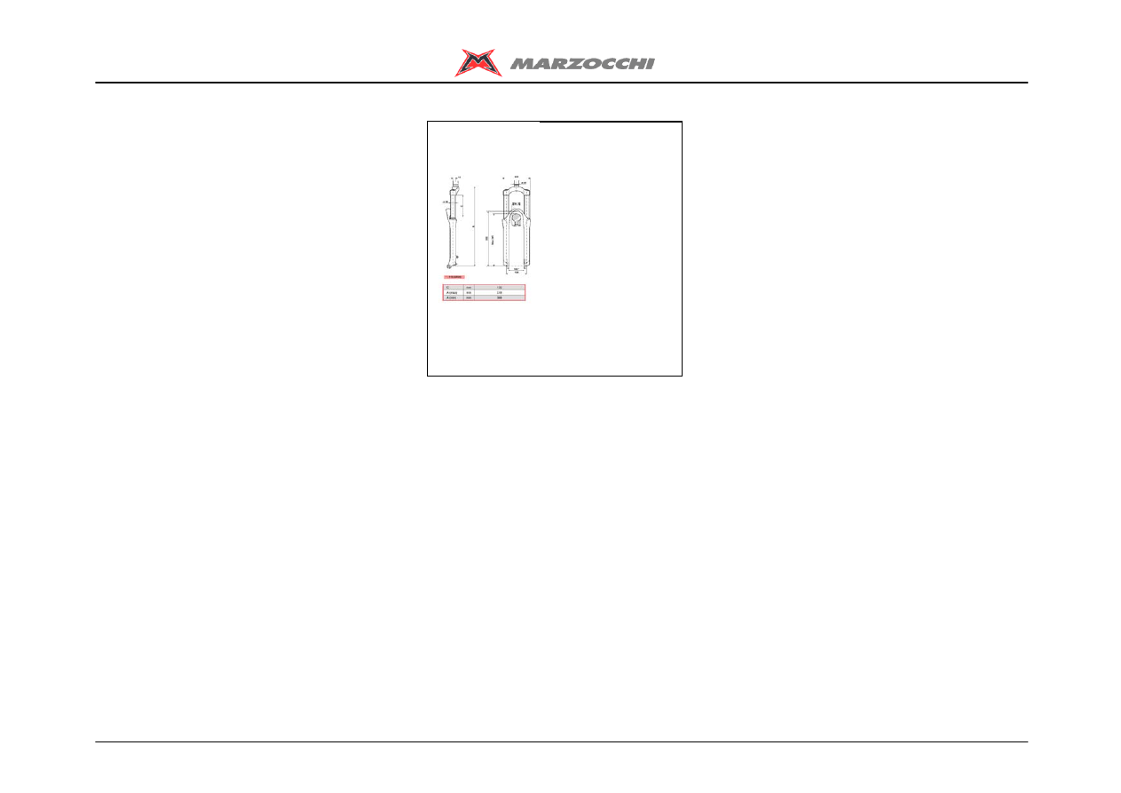
Features
TECHNICAL CHARACTERISTICS
Fork with Ø32 mm legs with spring and
hydraulic rebound damping.
Adjustment of the hydraulic rebound
braking through the knob on the top of the
right leg.
Adjustment of the air preload on the right
leg.
The ETA cartridge in the left leg makes it
possible to limit the extension blocking the
rebound of the fork.
The stanchion tubes are pressed into the
crown with a cryogenic process.
New sliding system to improve the stiffness
and operation.
Magnesium alloy cast one-piece assembly,
CNC machined for lighter weight and more
stiffness.
Components subjected to friction are
lubricated and cooled by means of a
special oil.
Steer tube: steel or reinforced aluminium,
1-1/8", threadless.
Crown: BAM® aluminium alloy forged and
CNC machined.
Stanchions: aluminium.
Springs: constant pitch.
Sliding bushes: made of friction free and
wear free material.
Seals: computer designed oil seals that
guarantee the maximum seal in any
condition.
Oil: special formulated oil that prevents
foam and keeps the viscosity unchanged
while offering high performance; free from
static friction.
Dropout type: Standard or (optional) QR20
Plus in the standard version or in the new
"With Bolt" version.
Disk brake mount: XC International
Standard for 6" disk.
Options: integrated fender.
BAM®: Bomber Aerospace Material:
special alloy coming from the aerospace
industry.
Z1 Free Ride
2/45
Features

Z1 Free Ride
3/45
Warning
INSTRUCTIONS FOR USE
GENERAL REGULATIONS
FITTING THE FORK ONTO THE FRAME
INSTALLING THE DISK BRAKE SYSTEM
ASSEMBLING THE FENDER
ASSEMBLING THE WHEEL ON FORKS WITH STANDARD DROPOUTS
ASSEMBLING THE WHEEL ON FORKS WITH QR20 PLUS DROPOUTS
ASSEMBLING THE WHEEL ON FORKS WITH QR20 "WITH BOLT" DROPOUTS

Z1 Free Ride
4/45
Warning
INSTRUCTIONS FOR USE
MARZOCCHI forks are based on an
advanced technology coming from the
company’s years long experience in the
professional mountain bike industry.
For the best results, it is advisable to
inspect and clean the area below the dust
seal and the stanchion tube after every use
and to lubricate the parts with some
silicone oil.
MARZOCCHI forks usually offer the best
performances since the very first rides.
Notwithstanding this, a short running-in
period may be necessary (5-10 hours) to
adjust the internal couplings. This
precaution will lengthen your fork’s life and
guarantee its best performances.
Changing the oil every 100 hours is
recommended.
The forks with a polished finish must be
treated periodically with polishing paste to
keep the exterior shining like new.

Z1 Free Ride
5/45
Warning
GENERAL REGULATIONS
· After a complete breakdown, always use
new MARZOCCHI seals when
reassembling.
· Before reassembly, wash all new and old
components and dry them with some
compressed air, making sure there are
neither breaks nor burrs.
· Never use flammable or corrosive
solvents to clean the parts as this could
damage the seals. If necessary use specific
detergents that are not corrosive, not
flammable or have a high flash point
compatible with the materials of the seals
and preferably biodegradable.
· Before reassembling, always lubricate the
parts of the fork in contact with some oil for
forks.
· Never pour lubricants, solvents or
detergents which are not completely
biodegradable in the environment; these
must be collected and kept in the relevant
special containers, then disposed of in
accordance with the regulations in force.
· Always grease the seal lips before
reassembling.
· Use only metric spanners and not
imperial. Imperial spanners may have
similar sizes to metric ones but they can
damage the bolts and screws making it
impossible to unscrew them.
· Use the right size and sort of screwdriver
to unscrew slotted or crosshead screws.
· When using a screwdriver to assemble or
dismantle metal stop rings, O-ring seals,
guide bushes or seal segments, avoid
scratching or cutting the components with
the tip of the screwdriver.
· Use only original spare parts.
· Before servicing the fork, we recommend
washing the fork thoroughly.
· Work in a clean, ordered and well-lit place.
· Carefully check there are no metal
shavings in the work area.

Z1 Free Ride
6/45
Warning
FITTING THE FORK ONTO THE FRAME
The fork is supplied with “A-Head Set” steer
tube to be cut according to frame size it will
be used on.
Fitting the fork onto the bike frame is a very
delicate operation that must be carried out
at one of our service centres only.
The assembling on the frame and the
adjustment of the steer tube must be
carried out following the instructions of the
steering set manufacturer.
A wrong installation can be dangerous
for the rider.
Marzocchi does not guarantee the
assembly and accepts no liability for
damage and/or accidents arising from a
wrong installation.
The steer tube must be pressed into the
crown; its replacement must be carried
out by one of our service centres using
the adequate tools.
A wrong installation of the steer tube
into the crown may cause the rider to
lose the control of the bike and lead to
serious personal injury.
Z1 Free Ride
7/45
Warning
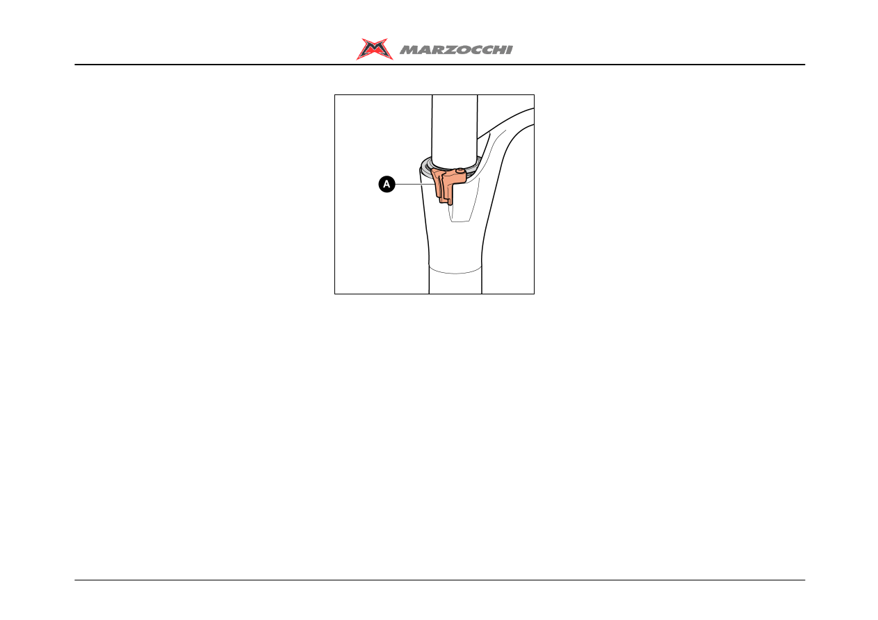
INSTALLING THE DISK BRAKE SYSTEM
Installing the brake system is a very
delicate operation that must be carried out
at our specialised service centres only.
Marzocchi does not guarantee the
installation and accepts no liability for
damage and/or accidents arising from a
wrong installation
Improper installation of the disk brake
system can overstress the caliper
mountings, which may break. The
installation of the brake system must be
carried out following the instructions of
the brake system manufacturer.
Improper installation can be dangerous
for the rider.
Use only brake systems in accordance with
the fork’s specifications.
After installation always check that the
brake tube is correctly fixed to the
special mount (A).
Z1 Free Ride
8/45
Warning
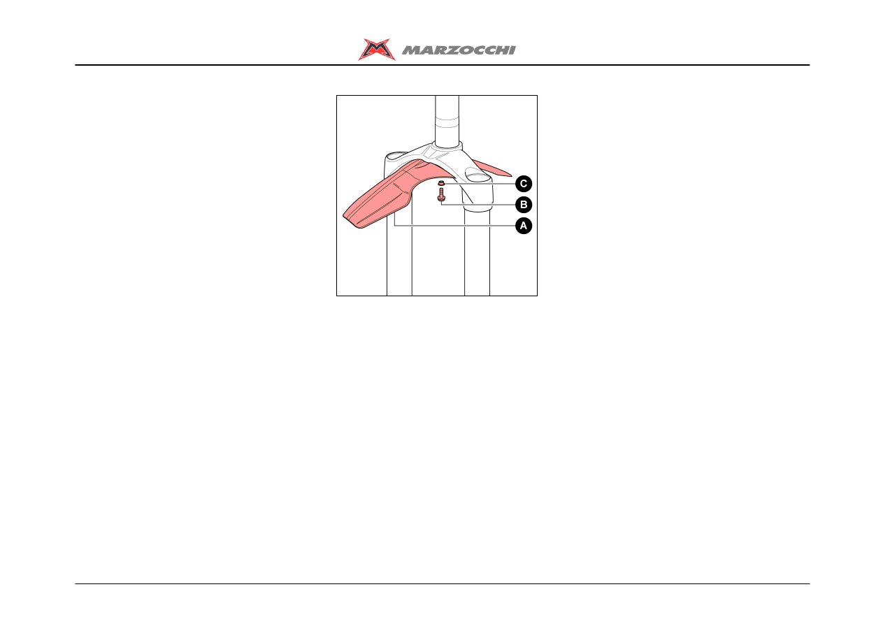
ASSEMBLING THE FENDER
The fender can be supplied with the fork or
purchased separately.
Assemble the fender (A) by inserting the
small support bush (C) between the screw
and the fender as shown, and by tightening
the screws (B) with an 8mm hexagonal
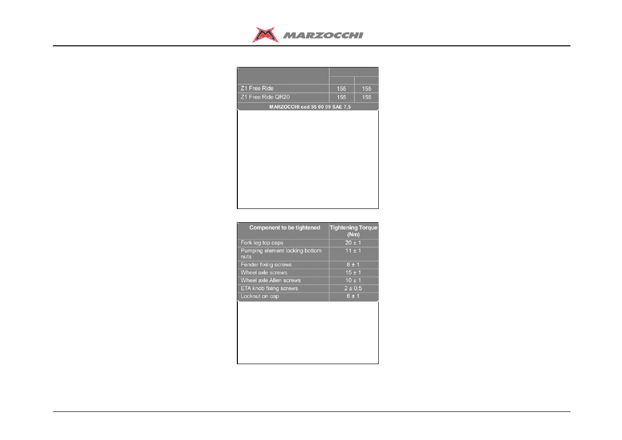
spanner to the required torque (8±1 Nm).

Z1 Free Ride
9/45
Warning
ASSEMBLING THE WHEEL ON FORKS
WITH STANDARD DROPOUTS
Install the wheel following the
instructions of the bike’s manufacturer.
A good and reliable operation of the fork
and all of the parts linked to it mainly
depend on the correct fixing of the front
wheel.
For a correct operation of the fork, install
the wheel as explained below:
Check the correct fork-wheel alignment by
fully compressing the fork a few times.
Lift the front wheel above the ground; turn
the wheel a few times to verify the correct
alignment with the disk brake.
Z1 Free Ride
10/45
Warning
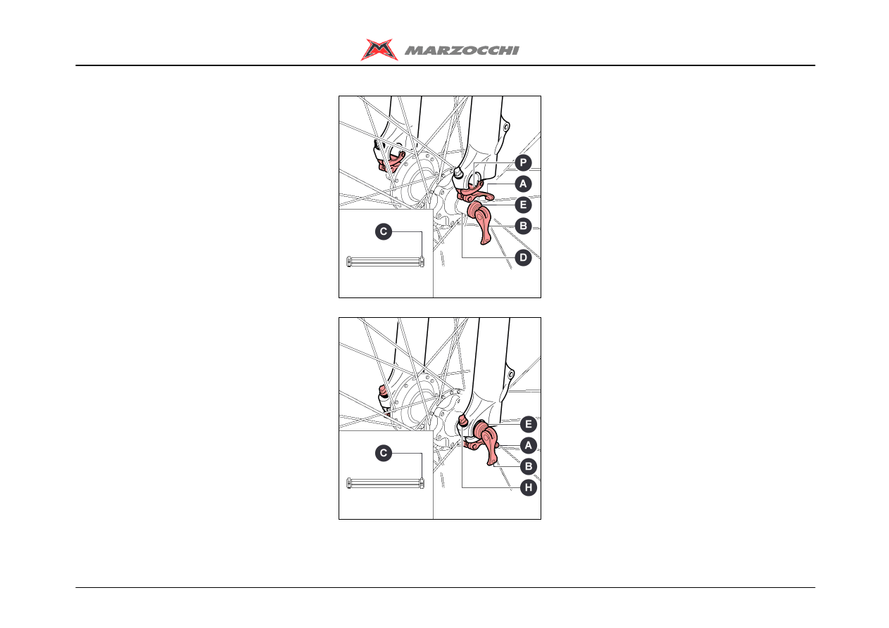
ASSEMBLING THE WHEEL ON FORKS
WITH QR20 PLUS DROPOUTS
A good and reliable operation of the fork
and all of the parts linked to it mainly
depend on the correct fixing of the front
wheel.
For a correct operation of the fork, install
the wheel as explained below:
· Unlock the locking device on both legs
pushing levers (A) downwards and opening
the small flap (P).
· For quick-release hubs, open the release
lever (B).
· For hubs with threaded cap, loose cap (C)
as much as needed to insert the wheel axle
through the wheel axle clamps.
· Insert the wheel axle (D) into the wheel
axle clamps.
· Check that the wheel axle supporting
bushes (E) are centred in the slider’s seat.
· If the wheel axle is equipped with a
quick-release system, lock the wheel with
the quick-release lever (B); otherwise, with
a 6mm Allen wrench, tighten the cap to the
side of the wheel axle to the recommended
tightening torque (see table - Tightening
torques).
· Verify the supporting bushes (E) stay
correctly.
· Check the correct fork-wheel alignment by
fully compressing the fork a few times.
the wheel a few times to verify the correct
alignment with the disk brake.
· Lock the locking device pulling levers (A)
upwards and adjust the clearance with the
adjusters (H), if necessary.
Z1 Free Ride
11/45
Warning
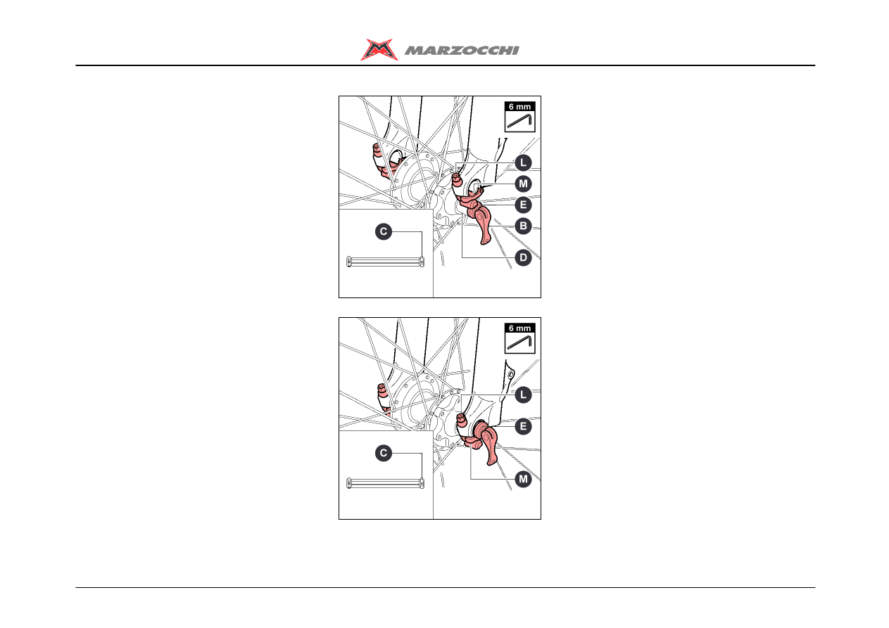
ASSEMBLING THE WHEEL ON FORKS
WITH QR20 "WITH BOLT" DROPOUTS
A good and reliable operation of the fork
and all of the parts linked to it mainly
depend on the correct fixing of the front
wheel.
For a correct operation of the fork, install
the wheel as explained below:
Using a 6mm Allen wrench, loosen both
screws (L) and open the locking device (M).
For quick-release hubs, open the release
lever (B).
For hubs with threaded cap, loose cap (C)
as much as needed to insert the wheel axle
through the wheel axle clamps.
Insert the wheel axle (D) into the wheel axle
clamps.
Check that the wheel axle supporting
bushes (E) are centred in the slider’s seat.
If the wheel axle is equipped with a
quick-release system, lock the wheel with
the quick-release lever (B); otherwise, with
a 6mm Allen wrench, tighten the cap to the
side of the wheel axle to the recommended
tightening torque (see table - Tightening
torques).
Verify the supporting bushes (E) stay
correctly.
Check the correct fork-wheel alignment by
fully compressing the fork a few times.
Lift the front wheel above the ground; turn
the wheel a few times to verify the correct
alignment with the disk brake.
Close the locking device (M) and tighten
both screws (L) with a 6mm Allen wrench.

Z1 Free Ride
12/45
Diagnostic

Z1 Free Ride
13/45
Disassembling
REMOVING THE TOP CAP – RIGHT LEG
REMOVING THE TOP CAP – LEFT LEG
DRAINING THE OIL
BREAKING DOWN THE CROWN-STANCHION UNIT / ARCH-SLIDER ASSEMBLY
REMOVING THE CARTRIDGE – LEFT LEG
REMOVING THE ETA CARTRIDGE - LEFT LEG
REMOVING THE SEALS
REMOVING THE GUIDE BUSHES
Z1 Free Ride
14/45
Disassembling
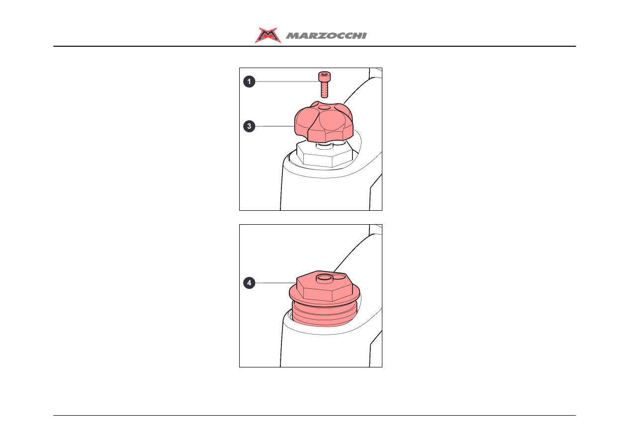
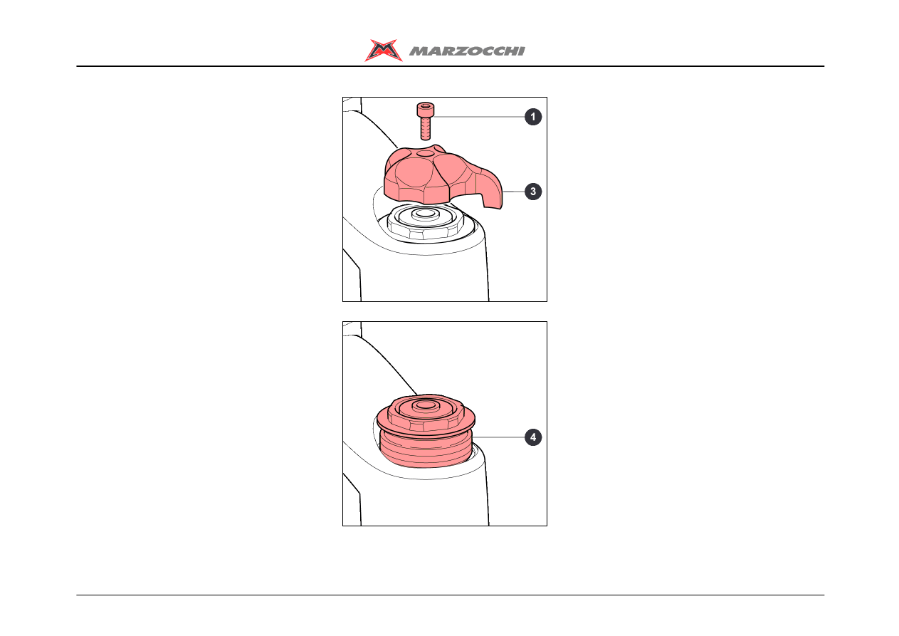
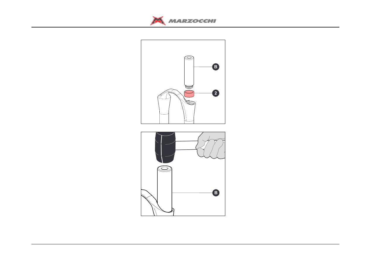
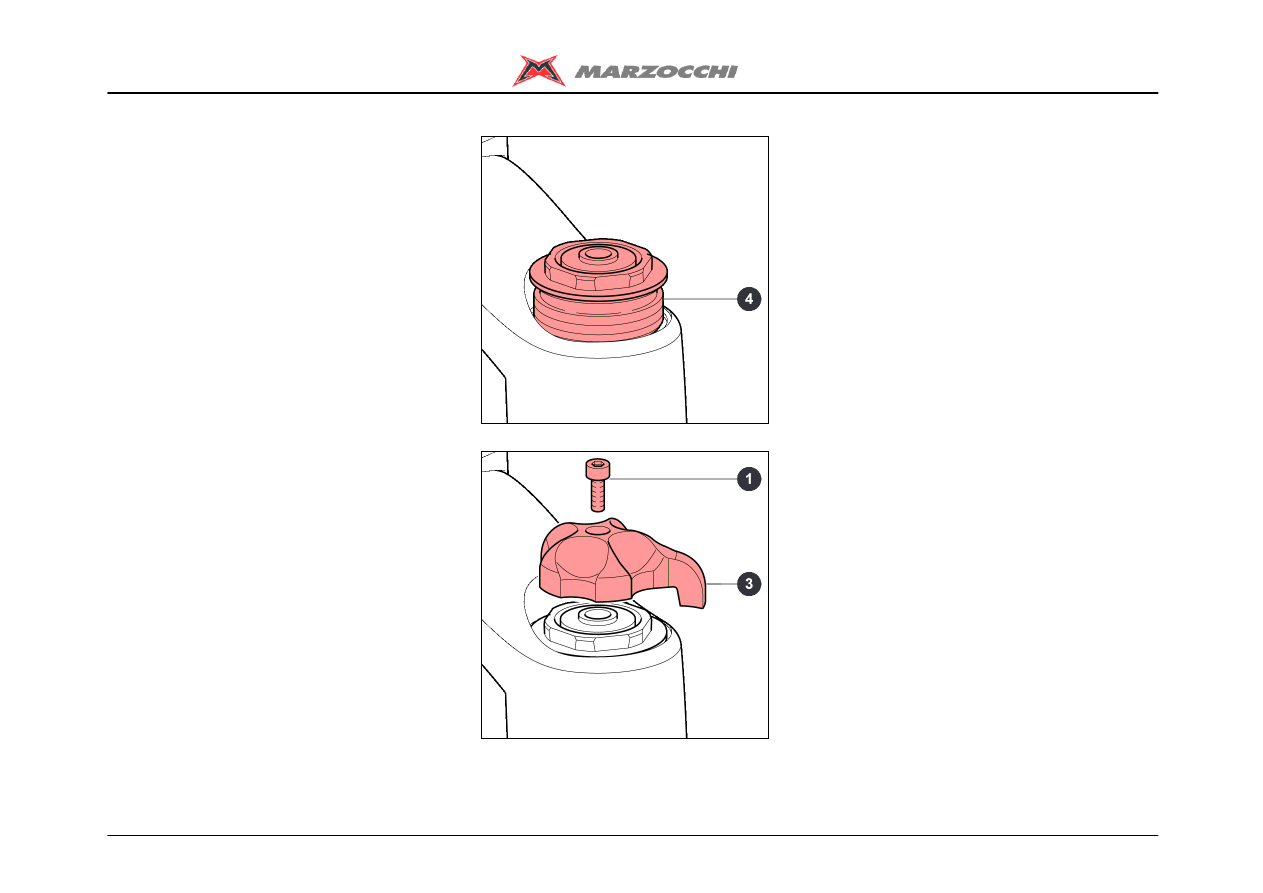
REMOVING THE TOP CAP - RIGHT LEG
· With a 2mm Allen wrench loosen screw (1
).
· Remove first the screw (1), then the
adjusting knob (3).
· Fully unscrew the lock cap (4), using a
21mm socket spanner.
· Lift out the lock cap (4).
Z1 Free Ride
15/45
Disassembling
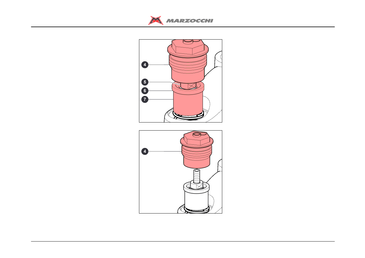
Push washer (6) and the preload tube (7)
downwards so you can reach locknut (5)
with a 10mm spanner.
· Holding locknut (5) with the 10mm
spanner, use the 21mm spanner to
unscrew the lock cap (4) completely.
· Remove the lock cap (4).
Z1 Free Ride
16/45
Disassembling
REMOVING THE TOP CAP – LEFT LEG
· With a 2mm Allen wrench loosen screw (1
).
· Remove first the screw (1), then the ETA
control knob (3).
· Fully unscrew the lock cap (4) using a
21mm socket spanner.
· Lift out the lock cap (4).
Z1 Free Ride
17/45
Disassembling
Push washer (6) and the preload tube (7)
downwards so you can reach locknut (5)
with a 10mm spanner.
· Holding locknut (5) with the 10mm
spanner, use the 21mm spanner to
unscrew the lock cap (4) completely.
· Remove the lock cap (4).
Z1 Free Ride
18/45
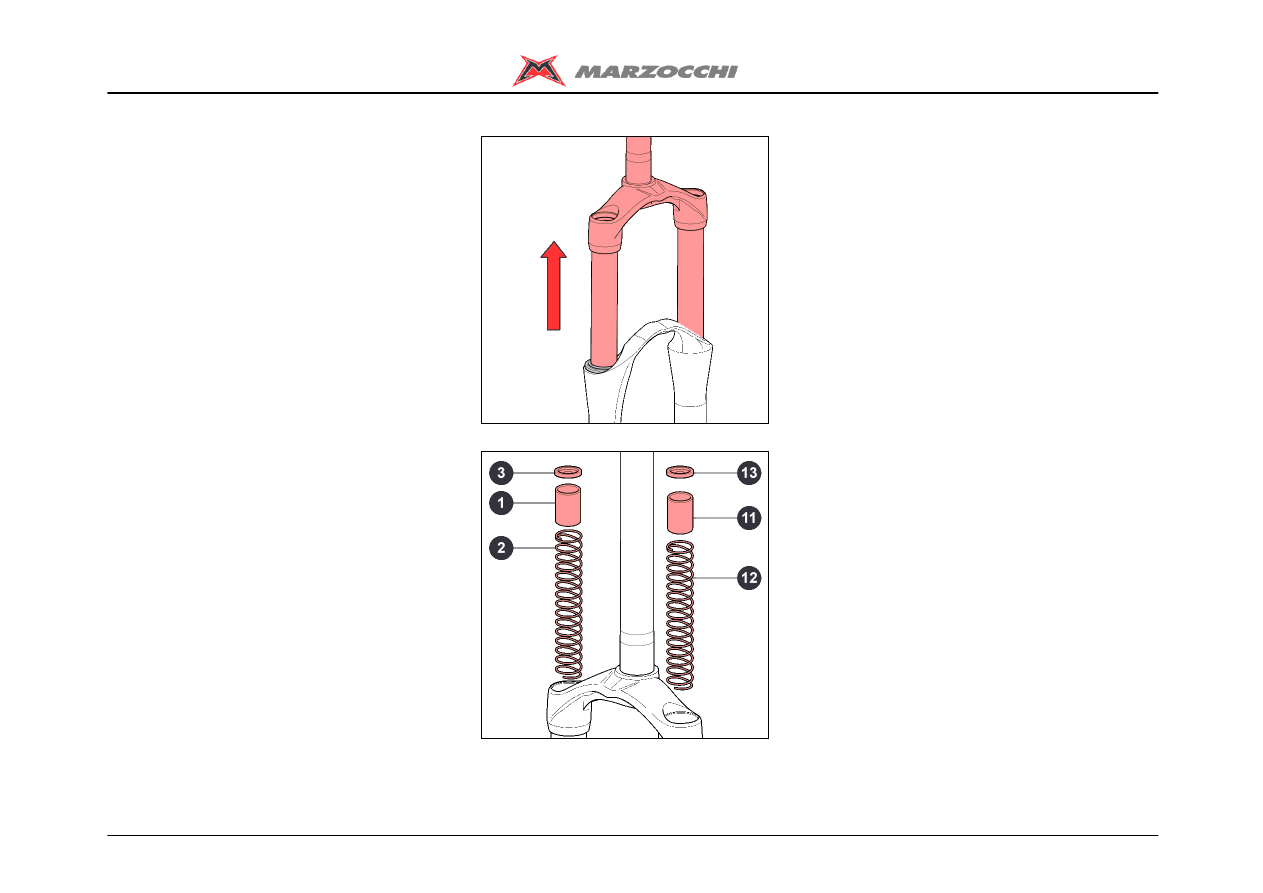
Disassembling
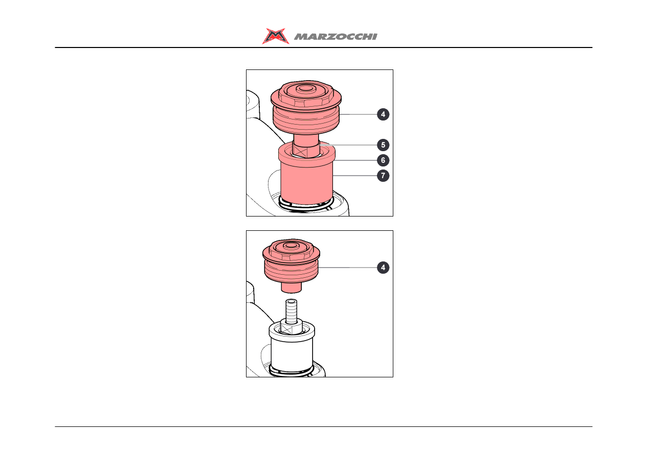
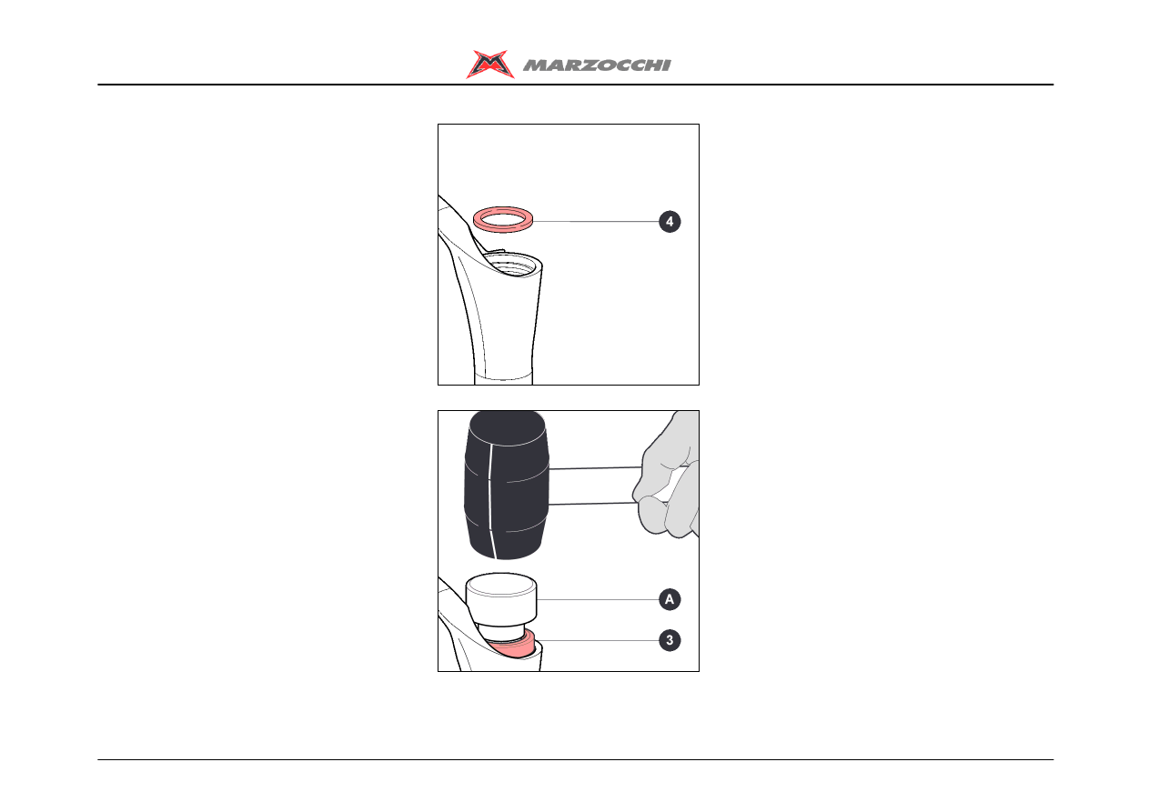
DRAINING THE OIL
· Remove washer (3), the preload tube (1)
and spring (2) from the right leg.
· Remove washer (13), the preload tube (11
), and spring (12) from the left leg.
· Free the fork from the vice and tip it into a
container of a suitable size to drain the oil;
compress the fork a few times to help the
oil flow out.
Do not pour used oils on the ground.
Z1 Free Ride
19/45
Disassembling
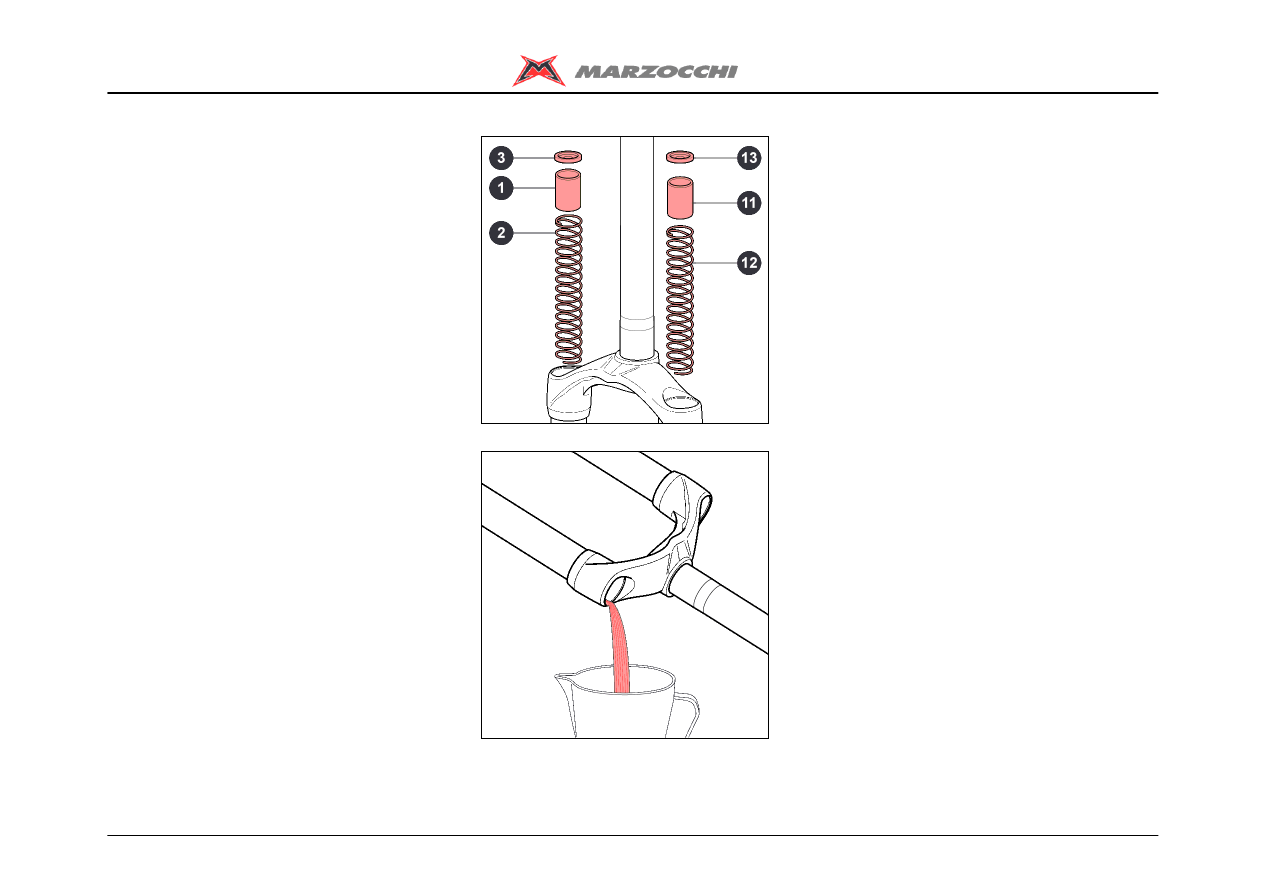
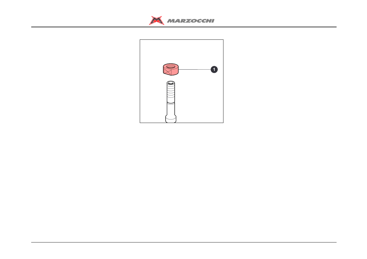
BREAKING DOWN THE
CROWN-STANCHION UNIT /
ARCH-SLIDER ASSEMBLY
Use the special spanner to remove the
bottom nuts. Do not use other tools.
Using the special 12mm spanner (A),
loosen the two bottom nuts (1).
Remove the bottom nuts (1) and the
O-rings (2).
Pull the complete hydraulic cartridge (10)
off the right leg.
Pull the complete ETA cartridge (9) off the
left leg.
Z1 Free Ride
20/45
Disassembling
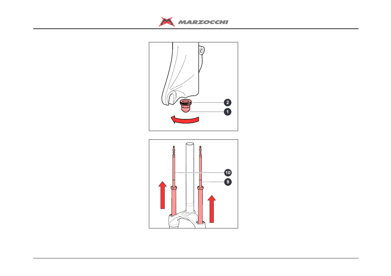
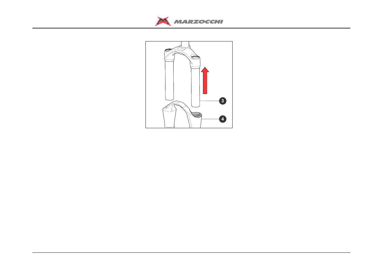
· Pull the crown-stanchion unit (3) off the
arch-slider assembly (4).
Z1 Free Ride
21/45
Disassembling
REMOVING THE HYDRAULIC
CARTRIDGE - RIGHT LEG
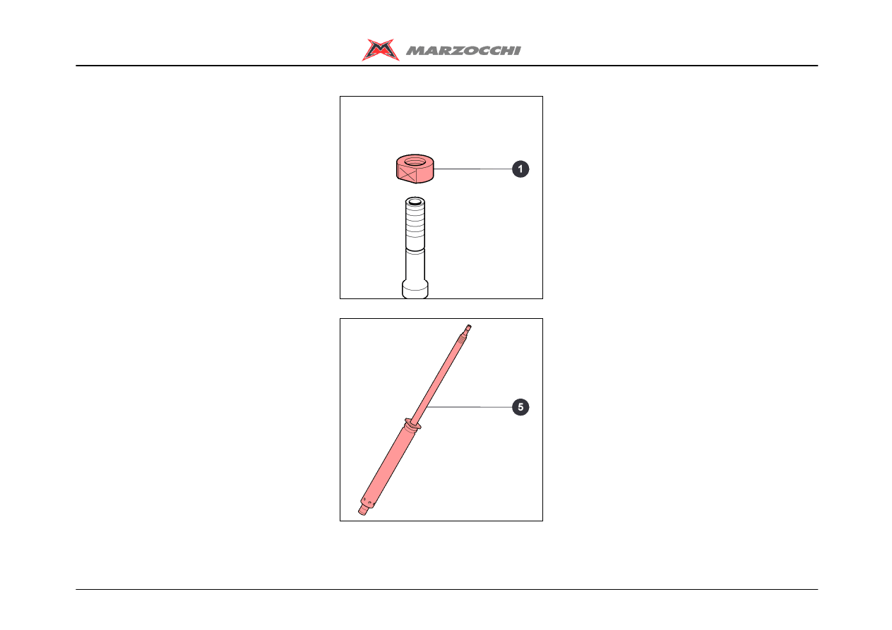
· Loosen and remove nut (1) with a 10mm
spanner with fixed jaws.
The hydraulic cartridge (5) has been
sealed through machining and cannot
be overhauled. In the case of faults or a
malfunctioning, this cartridge must be
replaced.
Z1 Free Ride
22/45
Disassembling
REMOVING THE ETA CARTRIDGE -
LEFT LEG
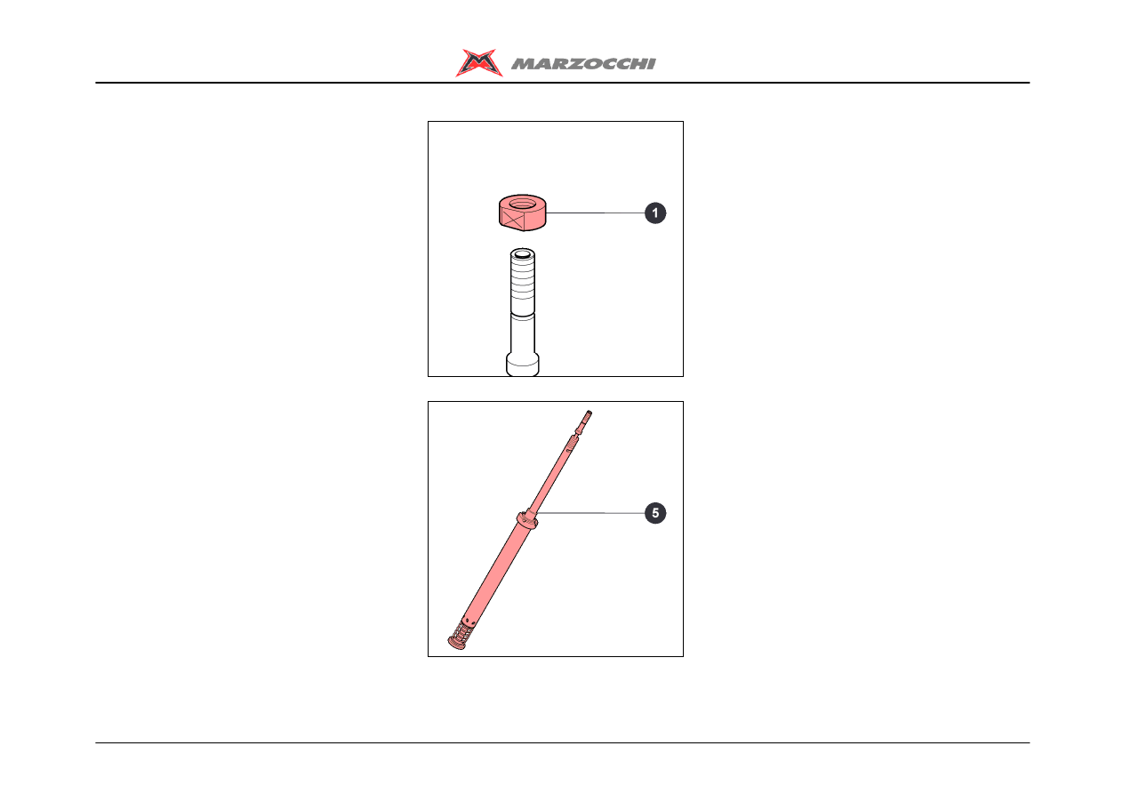
· Loosen and remove nut (1) with a 10mm
spanner with fixed jaws.
The ETA cartridge (5) has been sealed
through machining and cannot be
overhauled. In the case of faults or a
malfunctioning, this cartridge must be
replaced.
Z1 Free Ride
23/45
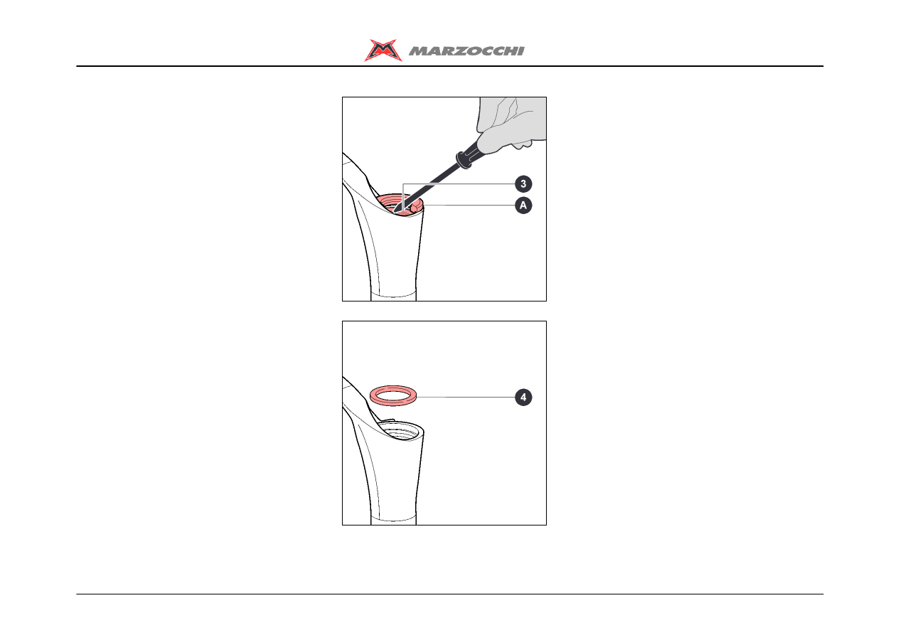
Disassembling
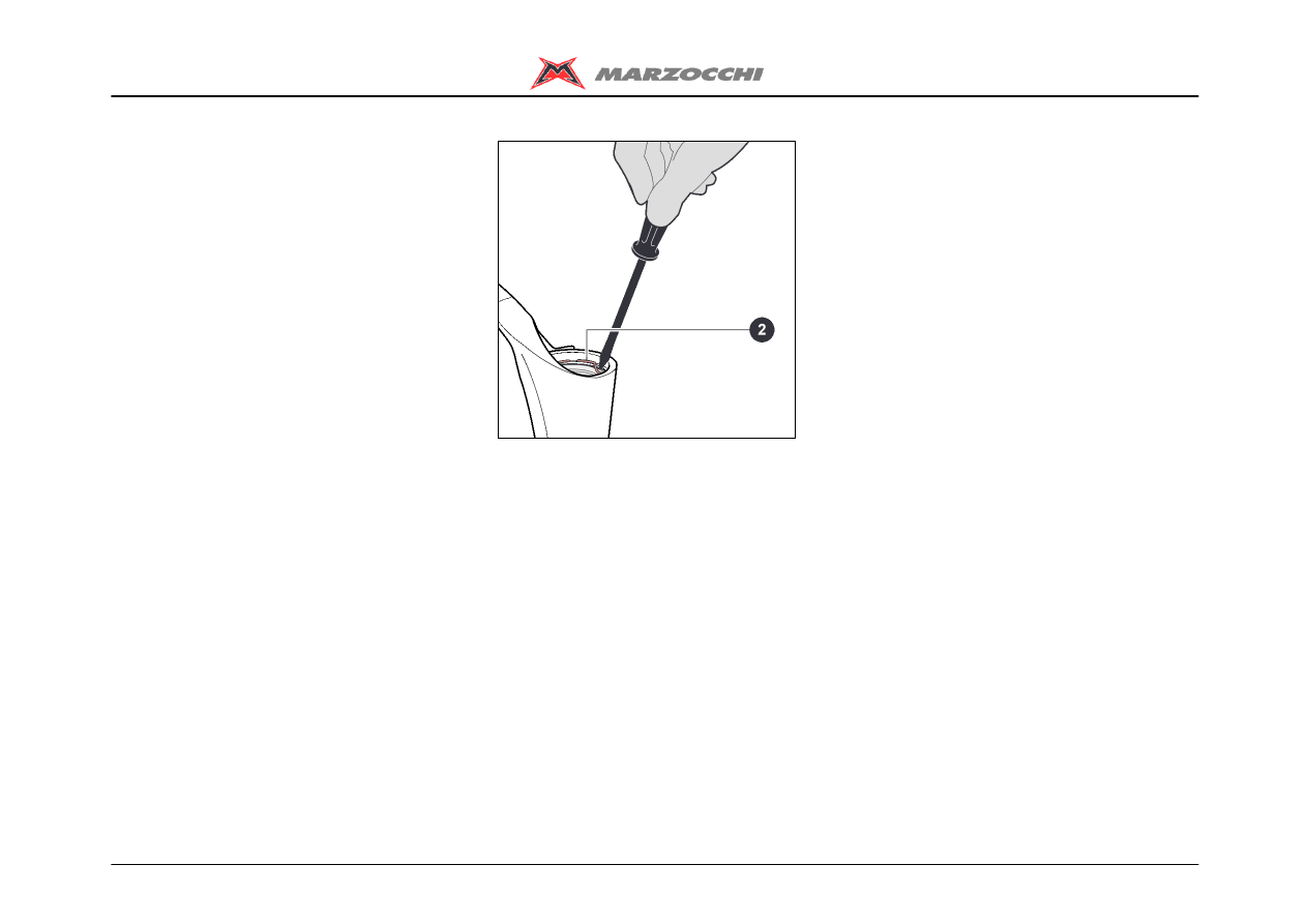
REMOVING THE SEALS
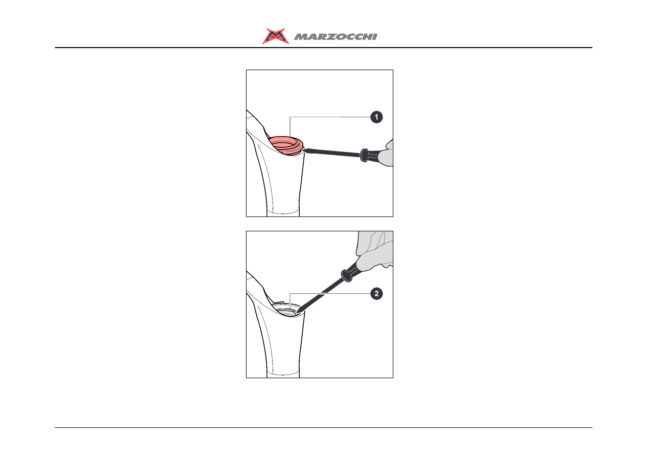
· Remove the dust seal (1) from its seat,
using a small flat-tip screwdriver.
· With the same screwdriver prize off the
metal stop ring (2).
Take great care not to damage the
internal surfaces of the arch-slider
assembly when removing the dust seal
and the stop ring.
Z1 Free Ride
24/45
Disassembling
Protect the upper part of the slider with the
special tool (A).
With a screwdriver prize the sealing ring (3)
off.
Remove the sealing ring (3).
Take great care not to damage the
internal surfaces of the arch-slider
assembly when removing the sealing
ring.
The old sealing rings and dust seals
must not be used again.
Remove the spring cup (4).
Z1 Free Ride
25/45
Disassembling
Protect the upper part of the slider with the
special tool (A).
With a screwdriver prize the sealing ring (3)
off.
Remove the sealing ring (3).
Take great care not to damage the
internal surfaces of the arch-slider
assembly when removing the sealing
ring.
The old sealing rings and dust seals
must not be used again.
Remove the spring cup (4).
Z1 Free Ride
26/45
Disassembling
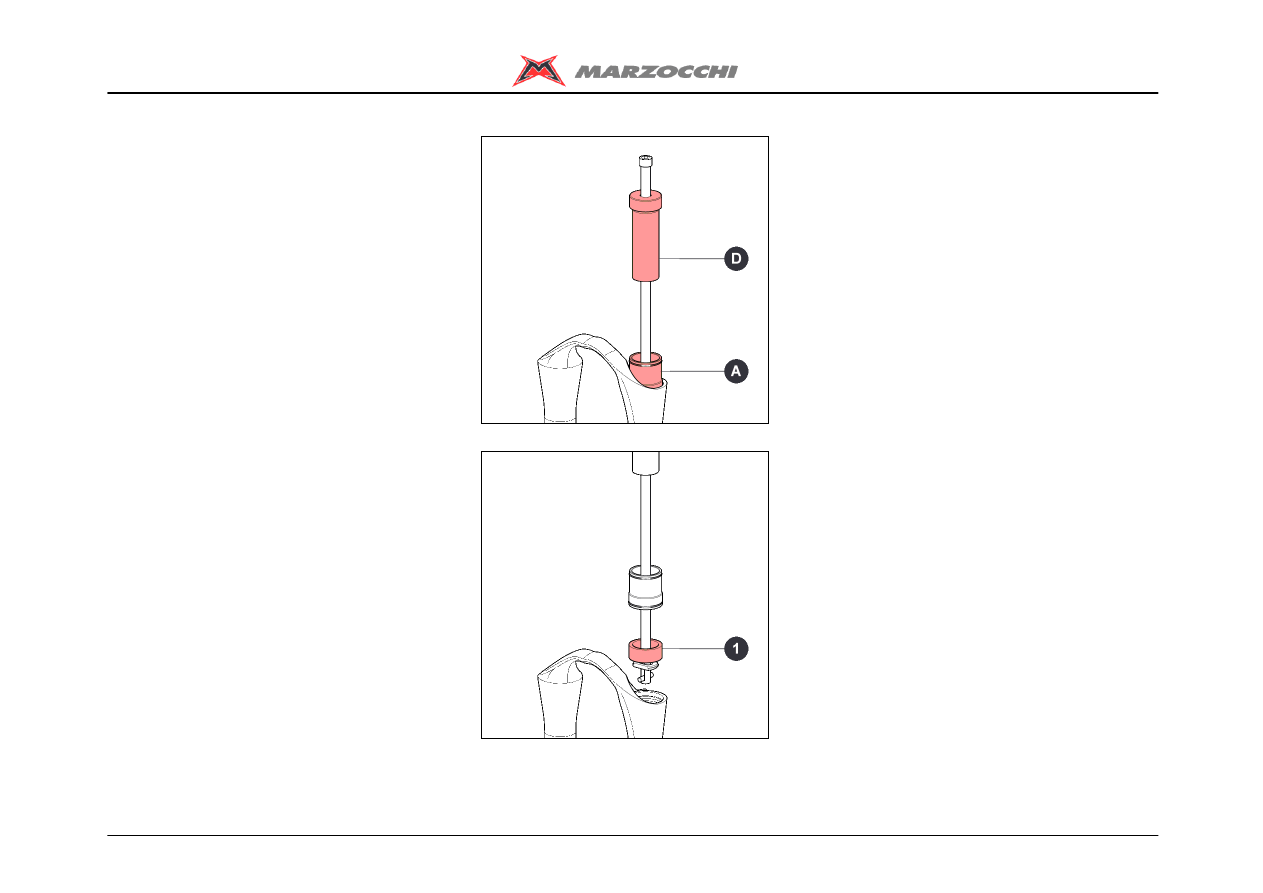
REMOVING THE GUIDE BUSHES
Use the special extractor to remove the
guide bushes. Do not use other tools.
Fit the aluminium bush (A) to the extractor
keeping the large diameter side towards the
edge opposite to the striker.
Fit the extraction washer (B) with a black
finish to the extractor.
During use, remove the non-used
washer from the extractor.
Remove first the top bushes, then the
bottom bushes.
Fit the extraction washer keeping the blunt
side towards the threaded grubscrew (C)
fixed crosswise on to the main rod as
shown.
The slot in the rod lets the extraction
washer swing inside the rod itself.
Insert the extractor in the arch-slider
assembly from the side of washer (B) as
shown.
The slot in the extractor rod will let the
washer pass underneath the bush to be
extracted.

Z1 Free Ride
27/45
Assembling
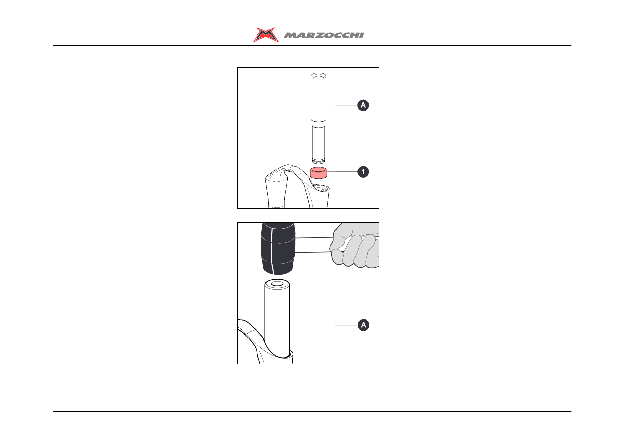
ASSEMBLING THE GUIDE BUSHES
Z1 Free Ride
28/45
Assembling
ASSEMBLING THE GUIDE BUSHES
Insert the guide bushes using the
special introducers (short type for the
top bush and long type for the bottom
bush, both with a white finish). Do not
use other tools.
Fit first the bottom bushes, then the top
bushes.
Using the long introducer (A) fit the bottom
bush (1).
Using a hammer knock the introducer (A)
into the arch-slider assembly.
Z1 Free Ride
29/45
Assembling
Using the short introducer (B) fit the top
bush (2).
Using a hammer knock the introducer (B)
into the arch-slider assembly.
Z1 Free Ride
30/45
Assembling
ASSEMBLING THE SEALS
· Fit the dust seal (4) in its seat.
· Smear the dust seal and the sealing ring
with some grease.
· Refit the sealing ring (3) using the special
introducer (A).
· Using a hammer knock in the introducer (A
) and drive the sealing ring home into the
arch-slider assembly.
Z1 Free Ride
31/45
Assembling
· With a small tip screwdriver mount the
stop ring (2) and check it fits perfectly into
its groove.
Take great care not to damage the
internal surfaces of the arch-slider
assembly when fitting the stop ring.
· The dust seals shall be refitted when
reassembling the crown-stanchion unit /
arch-slider assembly.
Z1 Free Ride
32/45
Assembling
MOUNTING THE HYDRAULIC
CARTRIDGE - RIGHT LEG
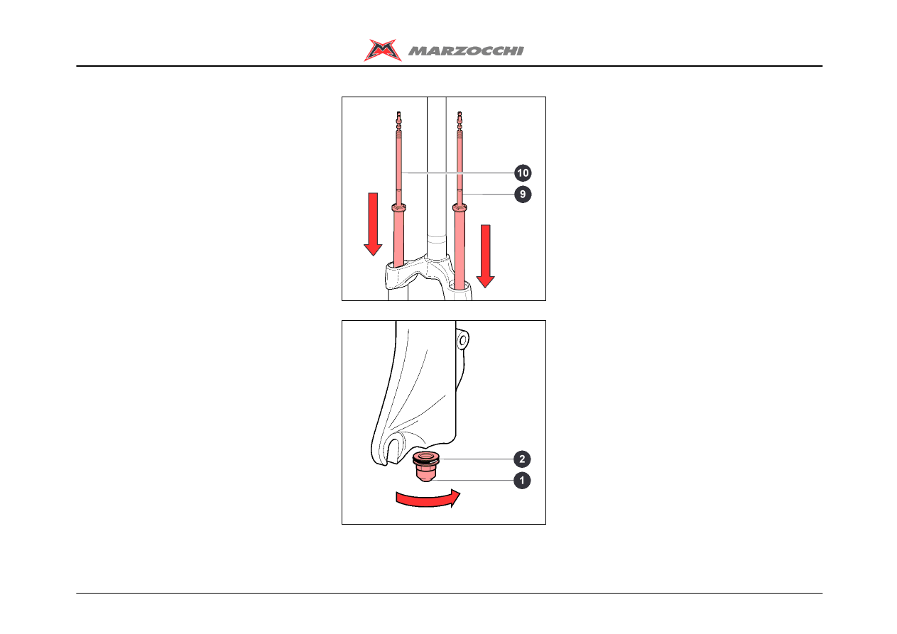
· Screw down nut (1) without tightening.

Z1 Free Ride
33/45
Assembling
ASSEMBLING THE ETA CARTRIDGE -
LEFT LEG
· Screw down nut (1) without tightening.
Z1 Free Ride
34/45
Assembling
ASSEMBLING THE CROWN-STANCHION
UNIT / ARCH-SLIDER ASSEMBLY
A special spanner shall be used to
assemble the bottom nut. Do not use
other tools.
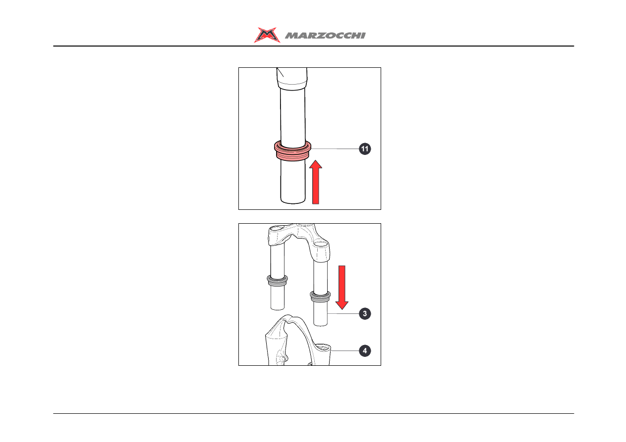
· Fit the dust seals (11) to the stanchions.
· Insert the crown-stanchion unit (3) in the
arch-slider assembly (4).
Z1 Free Ride
35/45
Assembling
· Fit the complete hydraulic cartridge (10) in
the right leg.
· Fit the complete ETA cartridge (9) in the
left leg.
· With the special 12mm spanner (A),
tighten the bottom nut (1) with O-ring (2) of
both legs to the recommended tightening
torque (11 Nm±1).
Z1 Free Ride
36/45
Assembling
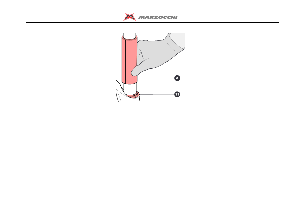
· Re-assemble the dust seals (11) in their
seats using the special introducer (A).
Z1 Free Ride
37/45
Assembling
FILLING WITH OIL
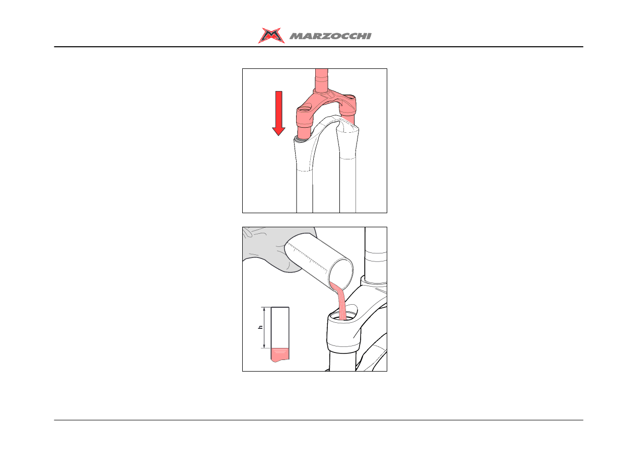
· Put the fork in the vice in vertical position.
· Lower the crown-stanchion unit on the
arch-slider assembly.
· Prepare the quantity of oil to pour into the
fork leg (see table).
· Pour roughly 1/3 of the oil required into
each stanchion, then pump the fork a few
times to remove any traces of air.
· Pour the rest of the oil in.
· Lower again the crown-stanchion unit on
the arch-slider assembly.
· Wait for a few minutes and check the
volume of the air (h); if necessary refill to
the right level.
A lower or higher volume of air, or a
type of oil other than the recommended
type can change the behaviour of the
fork in every phase.
Z1 Free Ride
38/45
Assembling
· Lift the crown-stanchion unit on the
arch-slider assembly.
· Insert spring (2), the preload tube (1) and
washer (3) in the right leg.
· Insert spring (12), the preload tube (11)
and washer (13) in the left leg.
Z1 Free Ride
39/45
Assembling
MOUNTING THE TOP CAP - RIGHT LEG
· Screw the lock cap (4) down on the
cartridge rod without tightening being very
careful not to damage the O-ring.
Push washer (6) and the preload tube (7)
downwards so you can reach locknut (5)
with a 10mm spanner.
· Using the 10mm and 21mm spanners,
tighten locknut (5) on cap (4) to the
recommended tightening torque (6 Nm±1).
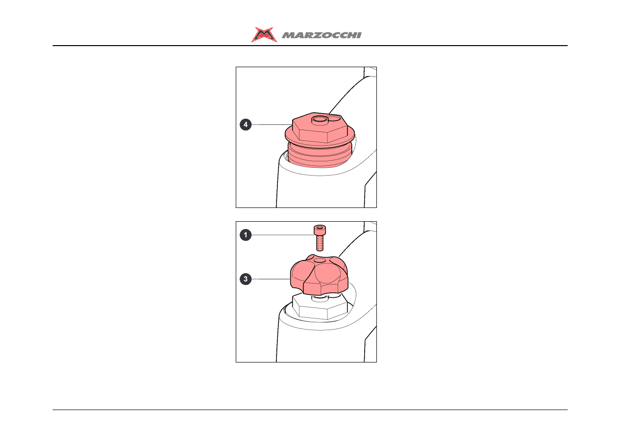
Z1 Free Ride
40/45
Assembling
· With the 21mm socket spanner, tighten
the lock cap (4) on the steering crown to the
recommended tightening torque (20 Nm ±1).
· Fit the adjusting knob (3) and screw (1).
· Using the 2mm Allen wrench, tighten
screw (1) to the recommended tightening
torque (2 Nm ± 0.5).
Z1 Free Ride
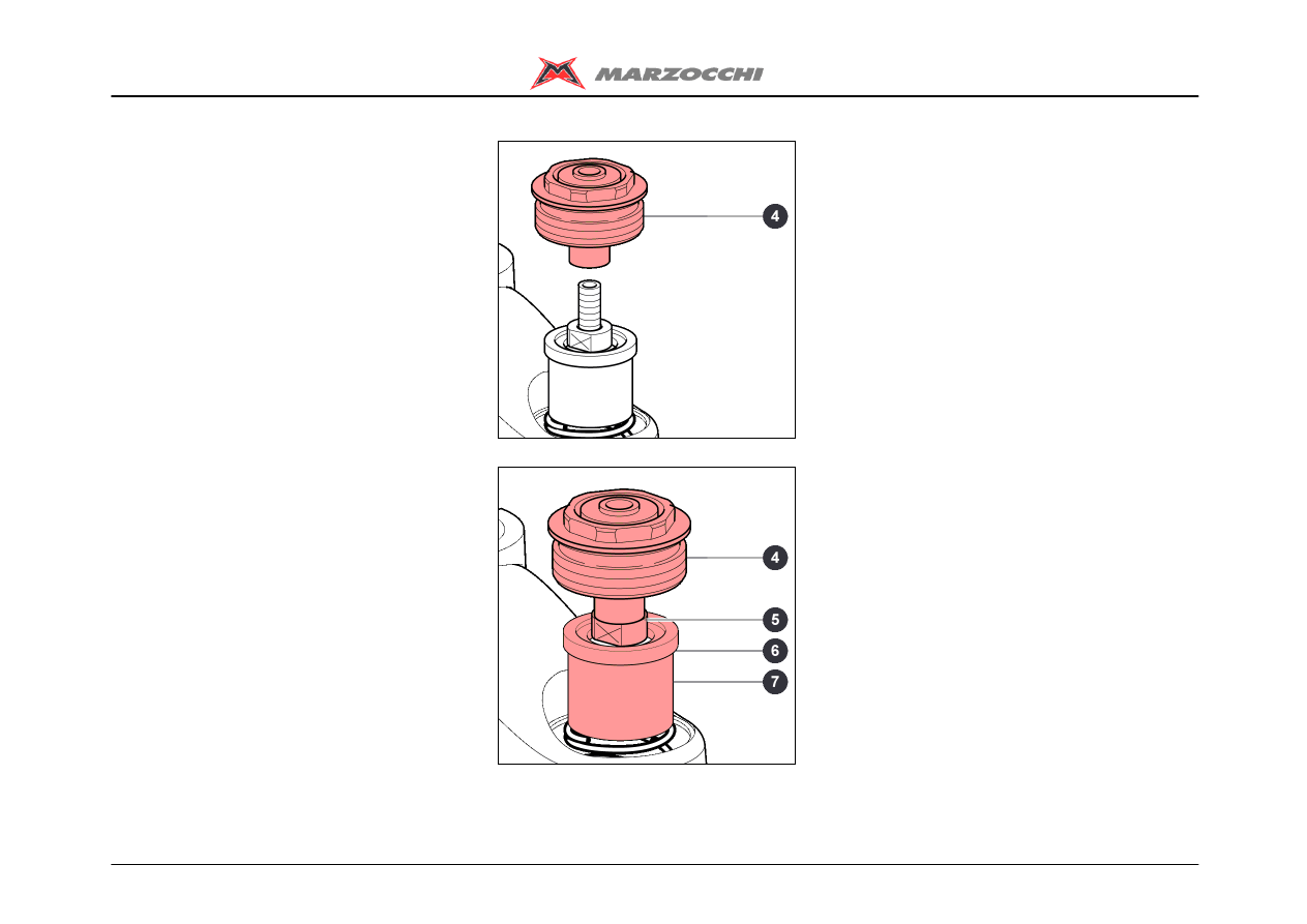
41/45
Assembling
MOUNTING THE TOP CAP – LEFT LEG
· Screw the lock cap (4) down on the ETA
cartridge rod without tightening being very
careful not to damage the O-ring.
Push washer (6) and the preload tube (7)
downwards so you can reach locknut (5)
with a 10mm spanner.
· Using the 10mm and 21mm spanners,
tighten locknut (5) on cap (4) to the
recommended tightening torque (6 Nm±1).
Z1 Free Ride
42/45
Assembling
· With the 21mm socket spanner, tighten
the lock cap (4) on the steering crown to the
recommended tightening torque (20 Nm ±1).
· Fit the ETA control lever (3) and screw (1).
· Using the 2mm Allen wrench, tighten
screw (1) to the recommended tightening
torque (2 Nm ± 0.5).

Z1 Free Ride
43/45
Settings
REBOUND ADJUSTMENT
ETA (TRAVEL LIMITING DEVICE)
Z1 Free Ride
44/45
Settings
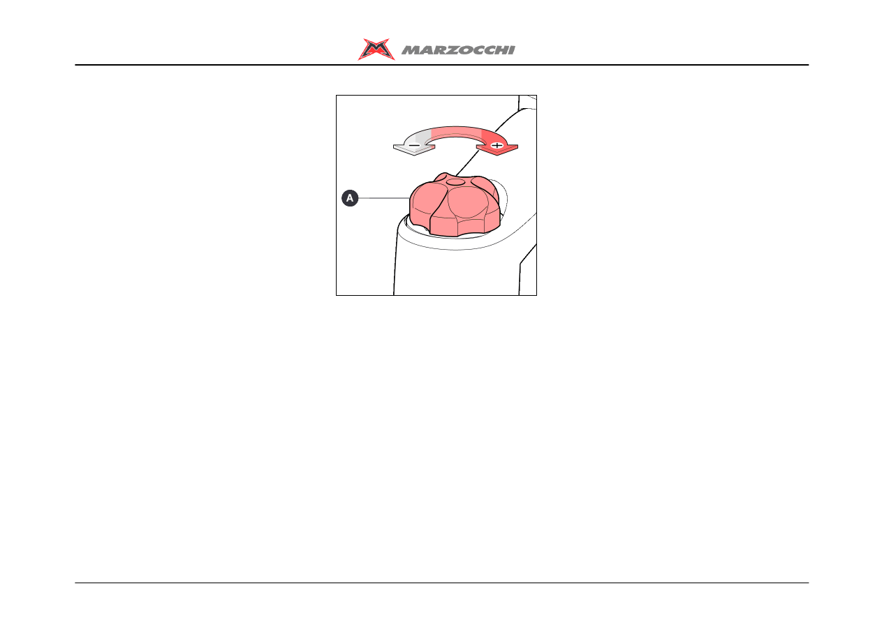
REBOUND ADJUSTMENT
With the adjuster (A), at the top of the right
leg, you can adjust the rebound damping.
Turning the adjuster modifies the hydraulic
configuration of the internal valves and lets
more or less oil flow through.
· Turning the adjuster clockwise increases
the hydraulic damping making the fork
slower during the rebound phase.
· Turning the adjuster counter-clockwise
decreases the hydraulic damping making
the fork more responsive during the
rebound phase.
Do not force the adjuster (A) beyond its
limit stops.
Z1 Free Ride
45/45
Settings
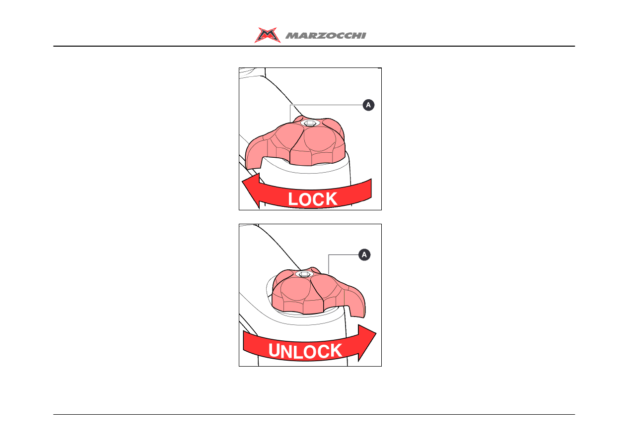
ETA (TRAVEL LIMITING DEVICE)
The ETA cartridge fitted to the left leg,
allows reducing the fork rebound limiting
the fork travel to 30 mm.
Turning the control (A) clockwise activates
the ETA cartridge function.
Turning the control (A) counter-clockwise
brings the fork back to normal function and
deactivates the limiting device.
Do not use the ETA devices when riding
on steep downhills. The fork would not
react safely enough when hitting an
obstacle.
Wyszukiwarka
Podobne podstrony:
2005 z1 fr 1
2002 L Z1 FR 110
2002 L Z1 FR QR20 130
2005 z1 fr 2
2005 z1 fr sl
2005 z1 fr 3
2004 Marzocchi Z1 Wedge instrukcja obsługi
Couronne O Sur les grands clusters en percolation (these, 2004)(fr)(en)(158s) MP
Airtronic 5 TD 08 2004 FR
ref 2004 04 26 object pascal
antropomotoryka 26 2004 id 6611 Nieznany (2)
2004 07 Szkoła konstruktorów klasa II
więcej podobnych podstron